

Page 1

GOLF COURSE EVACUATION SIREN KIT
INSTRUCTION LEAFLET
(Standard Horn Kit Product No. 18-980420)
Leaflet Contents
1. System Connection Diagram .......................................................... 2
2. Kit Contents .................................................................................... 2
3 Additional Equipment Requirement................................................. 2
4. Equipment Positioning .................................................................... 3
5. Installation....................................................................................... 3
6. Health & Safety Considerations ...................................................... 4
7 Accessory Product Information ....................................................... 4
Document No. 18-185835 Issue 3 Page 1 of 4
Page 2
GOLF COURSE EVACUATION SIREN KIT
INSTRUCTION LEAFLET
(Standard Horn Kit Product No. 18-980420)
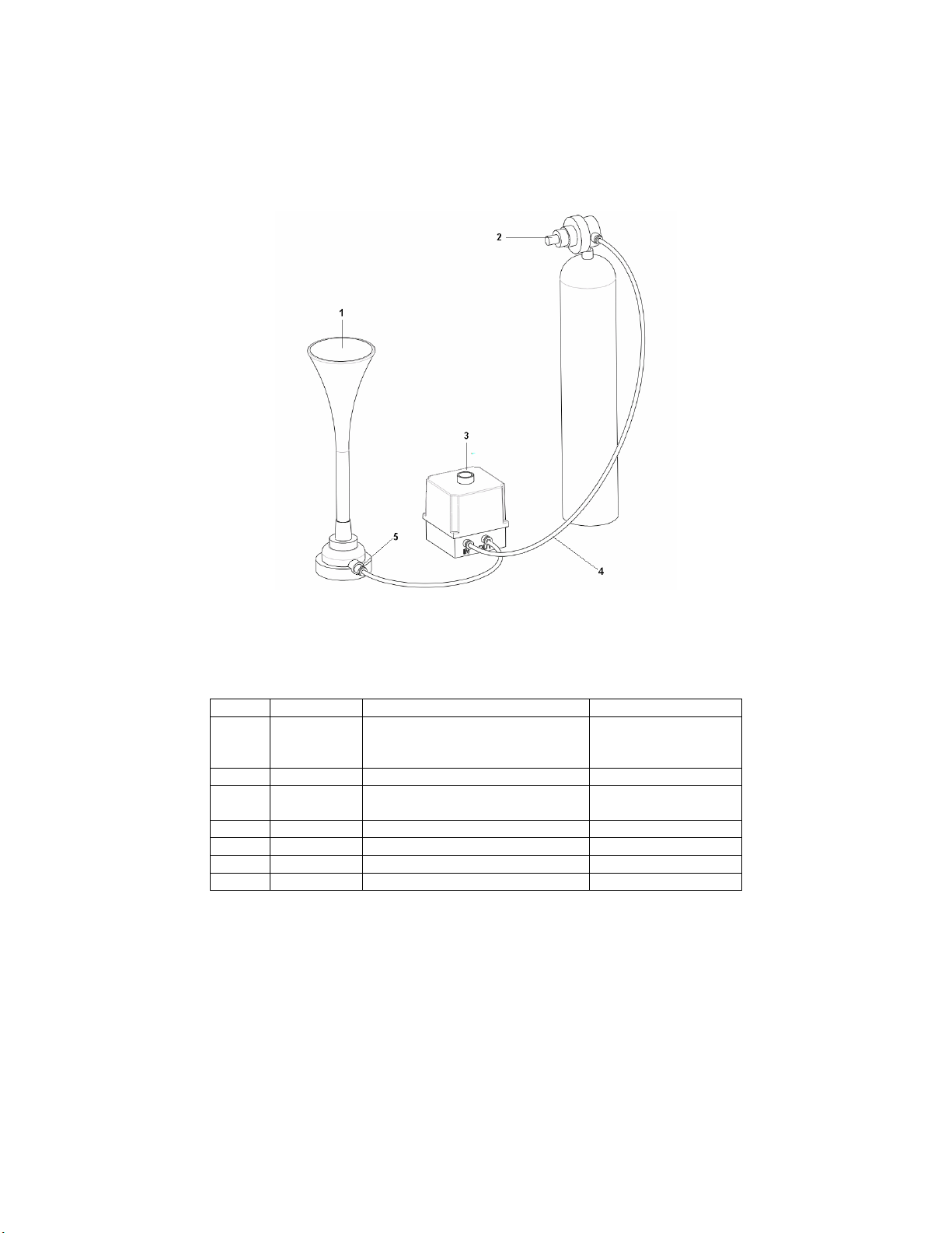
1. System Connection Diagram
2. Kit Contents
Item Qty Description Part Number
TDE 450 Air Horn
1 1
2 1 Air Regulator Preset to 80 PSI 18-185790
3 1
4 30 Metres Nylon Tube Air line 18-185792
5 1 Air Line Adaptor 8mm to ¼ BSP 18-185793
6 10 Air Line Pipe Retaining Clip 18-185794
or
TDE 360 Air Horn
Compressed Air Control Push
Button Mechanism
3. Additional Equipment Requirement
A compressed air cylinder containing Nitrogen gas is the only additional item of equipment required.
Note: It is recommended that either a spare full cylinder is kept in close proximity to the cylinder
attached to the system to facilitate a quick gas supply change when the active cylinder becomes
exhausted, or that the gas cylinder is regularly changed as part of a maintenance contract with the gas
supplier.
17-970042
or
17-970043
18-185791
Document No. 18-185835 Issue 3 Page 2 of 4
Page 3

GOLF COURSE EVACUATION SIREN KIT
INSTRUCTION LEAFLET
(Standard Horn Kit Product No. 18-980420)
4. Equipment Positioning
The horn is the only critical item of equipment to position and should be securely mounted to a pole or
the side of a building as far above the ground as practical with an unobstructed sound path over the
area it is to effectively operate over.
(Note: The unit is most audible in the direction the horn is pointed, to either side and especially the
area behind the horn the audibility will be reduced).
5. Installation
The following instructions provide guidance on the correct method of equipment installation.
• Check the contents of the kit are correct against the kit contents table.
• Remove and discard the attached air line coupling connector from the air horn by unscrewing it
from the base section and replace it with the air line adaptor provided, (item 5).
• Establish the desired wall location of the activation push button mechanism, (Item 3) and
secure firmly in position.
In order to secure the unit to the wall first unscrew the four captive screws holding the push
button mechanism enclosure together and then remove the two air couplings from the base
section of the unit. Following securing the base section of the mechanism to the wall using
suitable wall plugs and screws reverse the procedure to reassemble the unit.
• Establish the desired location of the air horn, (Item 1), and mount securely via the two 10mm
holes located in the base of the unit.
• Connect the nylon tube air line, (Item 4), to the air horn, (this is a push connection), and route
to the air line coupling labelled ‘Out’ located on the activation push button mechanism cutting
airline to length prior to insertion.
The air line can be held in position on the surfaces it is routed along by the air line retaining
clips supplied, (Item 6). Alternatively in order to protect the air line if vulnerable to damage due
to positioning, the air line could be routed inside conduit tubing.
• Attach the air pressure regulator, (Item 2), to the compressed nitrogen gas cylinder, ensuring
the cylinder outlet valve and the regulator inlet are clean and free from contaminants including
dirt, oil and water before fitting.
• With the remaining length of air line connect between the pressure regulator and the air line
coupling labelled ‘In’ located on the activation push button mechanism cutting the airline to
length prior to push insertion of air line into the couplings.
• The siren is now ready for activation following the opening of the gas cylinder valve.
Note: Closing the gas cylinder valve when the siren is not being activated is recommended.
Document No. 18-185835 Issue 3 Page 3 of 4
Page 4

GOLF COURSE EVACUATION SIREN KIT
Klaxon Signals Ltd
INSTRUCTION LEAFLET
(Standard Horn Kit Product No. 18-980420)
6. Health & Safety Considerations
• The air horn audibility level at 1 metre distance is 130dB and therefore care must be taken in
the positioning of the unit so that it is not in close proximity to people. (Recommended
minimum segregation distance between air horn and people of at least 5 metres).
During operation of the air horn if personnel are in close proximity ear defenders must be
worn.
• Do not use the air regulator if it shows signs of damage.
• Do not remove or change any component parts of the air regulator or air horn.
• Do not allow the associated nitrogen gas cylinders to become heated.
• Ensure the nitrogen gas cylinder is housed securely preventing it from toppling or rolling
around.
• Connection of the gas cylinder to the system should only be undertaken by competent
persons who understand the requirements controlling the use of compressed gases.
• When the siren is not in use it is recommended that the gas cylinder valve is closed and the
air contained in the air lines discharged by activating the siren briefly.
7. Accessory Product Information
Collapsible air horn mast: 18-185838 Nitrogen gas cylinder trolley: 18-185837
Wrigley Street, Oldham, Lancashire, OL4 1HW, UK.
Tel: +44 (0) 161 287 5555 Fax: +44 (0) 161 287 5511
E-mail: [email protected] Web: www.klaxonsignals.com
Document No. 18-185835 Issue 3 Page 4 of 4
 Loading...