

Page 1
Installation Instructions
Flashguard – The Installer’s Choice
Minn-X Internal Alarm Sounder
Minn-XE Internal Alarm Sounder with strobe
Minn-XW External Alarm Sounder
Minn-XE Manuel issue 4 no 2 25/3/03 7:59 am Page 3
Page 2
Installation Instructions
Thank you for buying Flashguard the generic term for sounder/strobe units.
BATTERY
(Not Minn-X)
PIEZO
SOUNDER
A
H
J
B
A
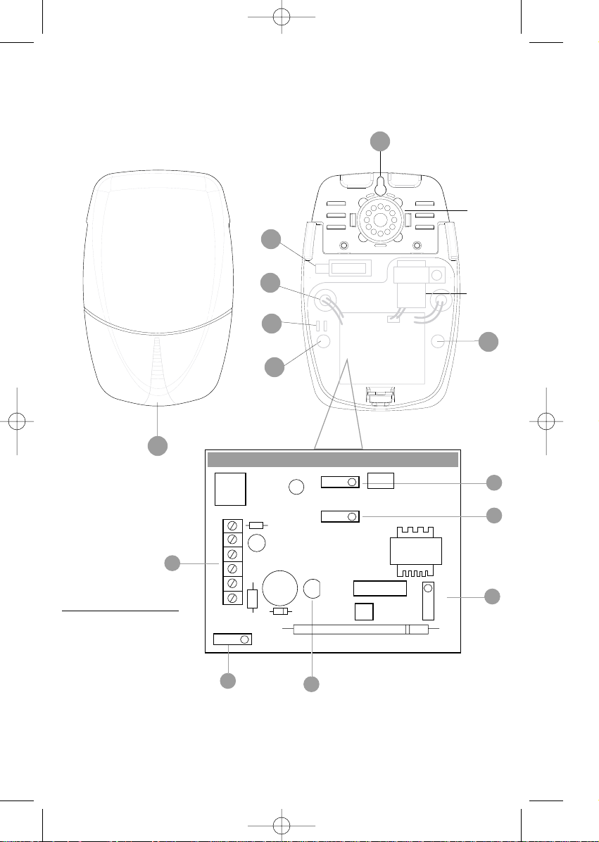
KEY
A
- Mounting Hole
B - Cable Entry Hole
C - Battery Jumper (not Minn-x)
D - Cut Off Timer Jumper (not Minn-x)
E - SAB/SCB Jumper (not Minn-x)
F - Connection Terminal Block
G - Series Tamper Jumper
H - Tamper Switch
I - Power LED
J - Cable Grips
K - Screw cover / lens
K
A
Minn-XE Manuel issue 4 no 2 25/3/03 7:59 am Page 4
PCB
Off On
Micro
Switch
1-STRODE
1
2
F
3
4
5
6
SERIES
TAMPER
2- TRIG 3- SUPPLY +
4- SUPPLY 5- TAMPER R
6- TAMPER S
G
Battery
SAB SCB
LED
WARNING - HIGH VOLTAGE
I
Warning
Protect
Hearing
Time
15 3
C
E
D
Page 3
Mounting Instructions
● Using the backplate of the unit (or the template on the rear of the carton), mark the position of
the screw holes (A) and cable entry hole (B) on the wall at the selected mounting position.
● Drill and plug the wall as marked.
● Using a long masonry bit, drill a hole through the wall to allow the cable to pass through.
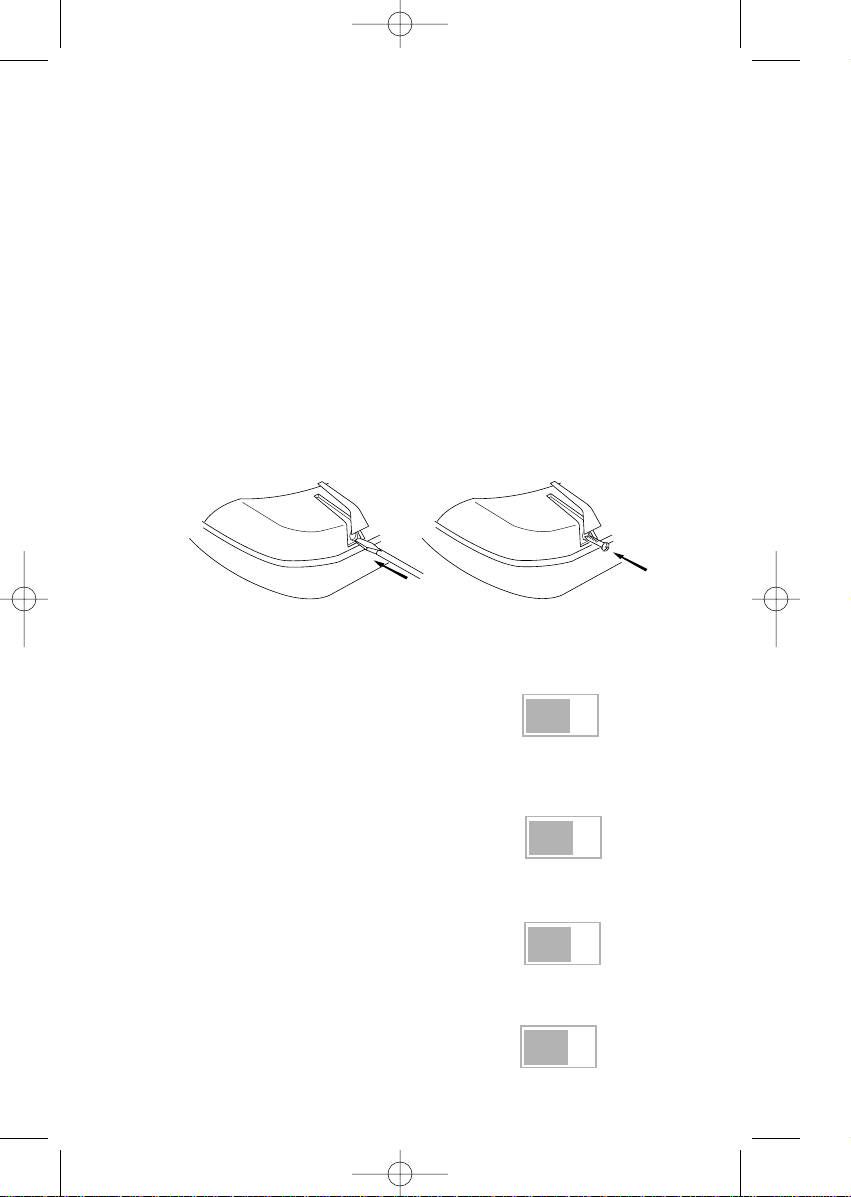
● To remove the front cover on the Minn-XW, gently remove the transparent cover using a screwdriver as shown
in fig 1 and remove the screw.
● Mount the unit on the wall with screws provided, not forgetting to pass the cable through the entry
hole on the backplate.
● Make the connections to the terminal block (refer to sections 3-4).
● Configure the jumpers as described in section 2 (not Minn-X).
● Replace the lid and tighten screw. (On Minn-XW, ensure the transparent screw cover is replaced, see fig 2)
● Alternatively, when used indoors the unit can also be connected to surface wiring or trunking using the
knock out cable entry on the top surface of the cover.
● The back plate also has mounting holes for attachment directly to a BS 4662 plaster depth back box.
Jumper Settings (Minn-X)
Battery (C)
Once installed, this jumper must be moved to the ON
position to connect the battery.
This will activate the automatic 5 second sound test.
The LED will not illuminate until the hold-off voltage is applied.
Cut Off Timer (D) - for the sounder
Can be set to either 15 or 3 minutes by putting
the jumper on the relevant pair of pins.
Note: Removing the jumper selects 3 minutes cut off time.
SAB / SCB Operation (E)
Move jumper to SCB position to minimise the current drawn from
control panel.A reduction in sound level occurs in SCB mode.
Series Tamper (G)
This jumper must be removed when the tamper loops of two
sounders are connected in series to the same control panel
1
2
Off On
O
SAB SCB
O
O
Time
15/3
Series
Tamper
O
fig 1 fig 2
Minn-XE Manuel issue 4 no 2 25/3/03 7:59 am Page 5
Page 4
Terminal Connections (F)
STROBE Applying a negative voltage triggers the strobe.
TRIG - Applying a negative voltage triggers the sounder.
SUPPLY + The permanent 12V DC supply from the panel is connected to these terminals.
If the hold-off supply is removed from these terminals, the unit will self activate on
SUPPLY - battery backup (Note: The LED will stop flashing on battery backup.)
TAMPER R Sounder tamper loop negative return.
TAMPER S This terminal is only used when connecting two units in series.
(Note: remove series tamper jumper when using tamper S input)
Typical Wiring Configurations
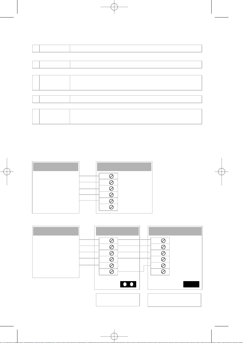
5 wire connection (with NiMH battery)
5 wire connections for 2 units in series (with NiMH battery)
3
4
1
2
3
4
5
6
Panel Sounder
0V Strobe
0V Sounder Trigger
+12V Hold off supply
0V Hold off supply
Tamper return
STROBE
TRIG SUPPLY +
SUPPLY TAMPER R
TAMPER S
1
2
3
4
5
6
0V Strobe
0V Sounder Trigger
+12V Hold off supply
0V Hold off supply
Tamper return
Remove Series Tamper jumper
(G) on PCB
Leave Series Tamper jumper
(G) on PCB
STROBE
TRIG SUPPLY +
SUPPLY TAMPER R
TAMPER S
1
2
3
4
5
6
1
2
3
4
5
6
Panel Sounder Sounder
}
Minn-XE Manuel issue 4 no 2 25/3/03 7:59 am Page 6
Page 5
Free Screen Printing
You supply the artwork and we will do the rest!
Let us create a professional company image which will heighten your company profile and place
an advertisement at every installation.
FREE screen printing is available on orders of more than 30 units.
For more information contact our Customer Services at
Telephone +44 (0) 161 287 5555
Facsimile +44 (0) 161 287 5511
Email [email protected]
6
Precautions
● Two Sounder units in series
Note: In this configuration the total current consumption can approach 900mA. Ensure that the alarm
panel can source this amount of current. If in doubt change the mode of operation of one or both units
to SCB to reduce the current load on the panel.
● PCB Handling
Note: The electronic strobe circuit can retain a stored charged for some time after the power to the
circuit is removed. Care should be taken when handling the PCB.
● Tamper Switch (H)
Care should be taken to ensure external wiring does not prevent the tamper switch from moving freely.
Ensure that the external cable is routed through the cable grips provided. (J)
● Location
Minn-XW is fully weatherproof to IP55 and is suitable for outdoor use. Minn-X and Minn-XE are only
intended for internal use. Ensure that these models are only installed in a dry location.
● Battery Replacement
Klaxon Signals recommends that the NimH battery be replaced every five years.
5
Minn-XE Manuel issue 4 no 2 25/3/03 7:59 am Page 1
Page 6
Wrigley Street • Oldham • Lancashire • 0L4 1HW
Telephone +44 (0) 161 287 5555 • Fax +44 (0) 161 287 5511
Email [email protected]
All information on this sheet is believed to be correct at the time of going to press.
Klaxon can accept no responsibility for damage caused by incorrect installation.
Technical Helpline & Sales Hotline
Technical Helpline: +44 (0)161 287 4029 • Sales Hotline: +44 (0)161 287 5555
42-103393/3
Technical Specification
Technical Specification Minn-X Minn-XE Minn-XW
Maximum Sounder Output (dBA @ 1m) 110 110
Strobe frequency (Hz) 1 N/A
Input Voltage
- Maximum 15 15
- Minimum 10 10
Current Consumption (mA) @ 13.2V
- Sounder (SAB mode) 300 300
- Sounder (SCB mode) 40 NA
- Strobe 130 N/A
- Standby Current 35 30
- maximum battery charge current (constant current charger) 20 N/A
Minn-XE Manuel issue 4 no 2 25/3/03 7:59 am Page 2
 Loading...