

Page 1
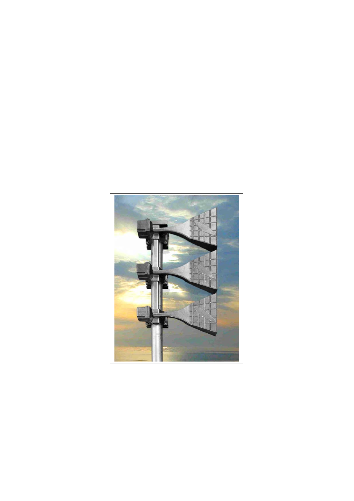
KLAXON SIGNALS
KLAXON
ES SIREN MAST
ASSEMBLY
GUIDELINES
Klaxon Signals
Wrigley St
Oldham
Lancs
OL4 1HW
Phone: ++ 44 (0) 161 287 5555
Fax: ++ 44 (0) 161 287 5511
Email: [email protected]
SG001a Issue 1 Dec 06
Page 2

KLAXON SIGNALS
CONTENTS
1. SIREN HORN CABLE(S) MANUFACTURE......................................... 2
1.1 Cable Specification............................................................................2
2. SIREN CABLE CONSTRUCTION TABLES......................................... 3
2.1 Turbo 2 (2 Horn / 1 Cable).............................................................. 3
2.2 Turbo 3 (3 Horn / 2 Cable).............................................................. 4
2.3 ES-2 (6 Horn / 1 Cable).................................................................. 5
2.4 ES-3 (12 Horn / 1 Cable)................................................................ 5
2.4 ES-3 (12 Horn / 1 Cable)................................................................ 6
2.5 ES-4 (18 Horn / 2 Cable)................................................................ 7
3. CABLE JUNCTION BOX ASSEMBLY INSTRUCTIONS ..................... 9
3.1 PURCHASED COMPONENTS....................................................10
4. MAST ASSEMBLY INSTRUCTIONS................................................. 11
5. HORN ARRAY DIMENSIONS & WEIGHT......................................... 22
6. HORN ASSEMBLY TESTING............................................................ 22
7. STANDARD SIREN MAST INFORMATION ...................................... 23
7.1 Mast Lengths, Weights and Number of Horns.............................. 23
7.2 Mast Fixing Bolts..........................................................................23
7.3 Mast Base Construction ............................................................... 23
7.4 Standard Mast Drawings.............................................................. 24
7.4.1 3 Metre Mast (18-185938) ..................................................... 25
7.4.2 4.5 Metre Mast (18-185939) .................................................. 26
7.4.3 6 Metre Mast (18-185940) ..................................................... 27
7.4.4 12 Metre Support Mast (18-185941)......................................28
7.4.5 12 Metre Support Mast Mounting Flange 1 (18-185942) .......29
7.4.6 12 Metre Support Mast Mounting Flange 2 (18-185943) .......30
7.4.7 Turbo 2/3 & ES2 Siren Horn Cable Box Bracket (18-186209)31
7.4.8 ES3 & ES4 Siren Horn Cable Box Bracket (18-186210)........ 32
SG001a Issue 1 1 of 32 Apr 07
Page 3
KLAXON SIGNALS
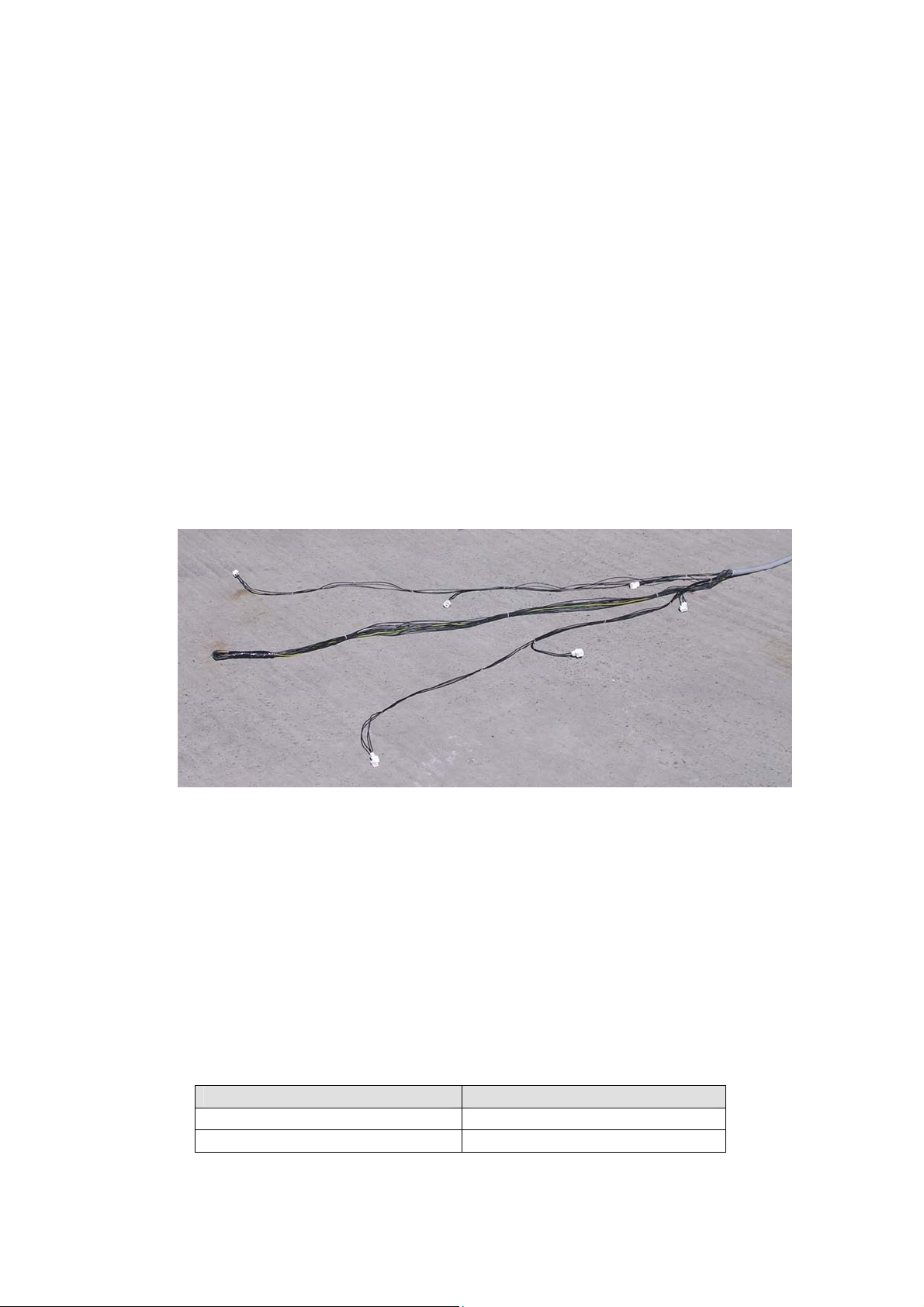
1. SIREN HORN CABLE(S) MANUFACTURE
1. Identify the siren type for which the cable is to be constructed and use
the tables appended to the bottom of this section for connection
information.
2. Determine the length of the cable required and cut cable to length.
(Length of mast + 1 metre + the length of the longest conductor stated
in the siren type table).
3. Cut the protective sheath back to the length of the longest required
conductor specified in the siren type table and remove.
4. Cut the respective conductors to the lengths specified in the siren
type table and remove.
5. If a single cable is being used then loom the conductors as specified
in the siren type table.
6. Crimp the connector plug onto the individual conductors and then
insert the crimped connectors into the connector housings.
Note: When the wires are inserted into the connectors the orientation
of odd or even numbered wires to the left hand or the right hand side
does not matter as long as they are all orientated in the same
manner.
1.1 Cable Specification
Siren Type Cable Required
Turbo 2, Turbo 3 4 Core 1.5mm2 YY Cable
ES-2, ES-3, ES-4 25 Core 1.5mm2 YY Cable
SG001a Issue 1 2 of 32 Apr 07
Page 4
KLAXON SIGNALS
2. SIREN CABLE CONSTRUCTION TABLES
Dependent on the number of horns associated with the siren one or two
cables will be required. The tables below identify specific requirements
based on the siren type.
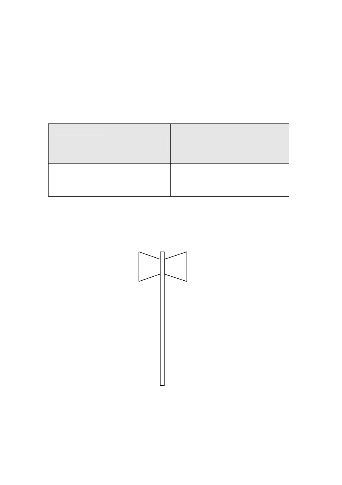
2.1 Turbo 2 (2 Horn / 1 Cable)
Length of individual wires from
Horn Number
& Amplifier
1/ Amp 1 1 & 2 240
2/ Amp 1
Note: Cable to be used is a four core cable with three cores being
numerically identified and the remaining core being the green/yellow earth
core.
GREEN/YELLOW
Wire
Identification
Numbers
3 &
Turbo 2 Horn Arrangement
the point where the outer sheath
of the multi-core cable is
terminated.
(mm)
240
Horn 1Horn 2
SG001a Issue 1 3 of 32 Apr 07
Page 5
KLAXON SIGNALS
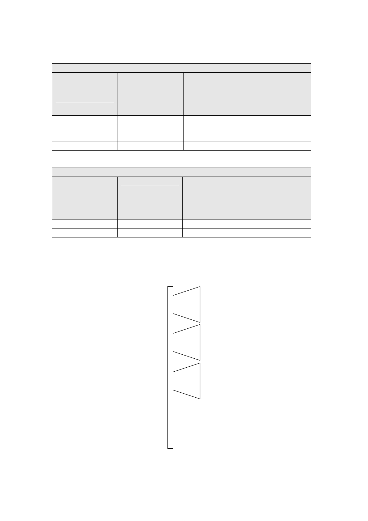
2.2 Turbo 3 (3 Horn / 2 Cable)
CABLE 1
Length of individual wires from
Horn Number
& Amplifier
Wire
Identification
Numbers
the point where the outer sheath
of the multi-core cable is
terminated.
(mm)
1/Amp 1 1 & 2 240
2/Amp 1
GREEN/YELLOW
3 &
880
CABLE 2
Length of individual wires from
Horn Number
& Amplifier
Wire
Identification
Numbers
the point where the outer sheath
of the multi-core cable is
terminated.
(mm)
3/Amp 1 1 & 2 240
Note: Cable to be used is a four core cable with three cores being
numerically identified and the remaining core being the green/yellow earth
core.
Horn 1
Horn 2
Horn 3
Turbo 3 Unidirectional Horn Arrangement
SG001a Issue 1 4 of 32 Apr 07
Page 6
KLAXON SIGNALS
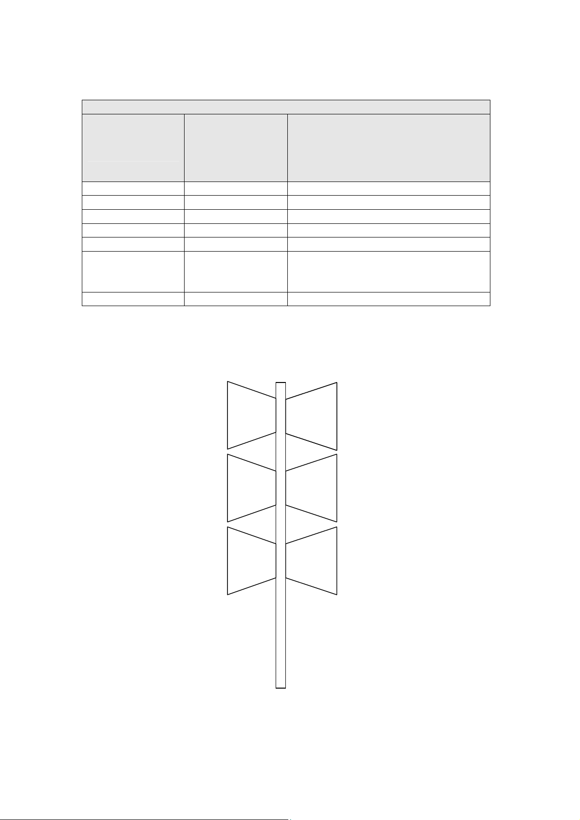
2.3 ES-2 (6 Horn / 1 Cable)
CABLE 1
Length of individual wires from
Horn Number
& Amplifier
Wire
Identification
Numbers
the point where the outer sheath
of the multi-core cable is
terminated.
(mm)
1/Amp 1 1 & 2 240 (Loom in cable loom 1)
2/Amp 1 3 & 4 880 (Loom in cable loom 1)
3/Amp 1 5 & 6 1520 (Loom in cable loom 1)
4/Amp 2 11 & 12 240 (Loom in cable loom 2)
5/Amp 2 13 & 14 880 (Loom in cable loom 2)
15 & 16
6/Amp 2
(All unused
1520 (Loom in cable loom 2)
wires)
Note: Cable to be used is a 25 core cable with 24 cores being numerically
identified and the remaining core being the green/yellow earth core.
Horn 4
Horn 5
Horn 6
Horn 1
Horn 2
Horn 3
ES-2 Horn Arrangement
SG001a Issue 1 5 of 32 Apr 07
Page 7
KLAXON SIGNALS
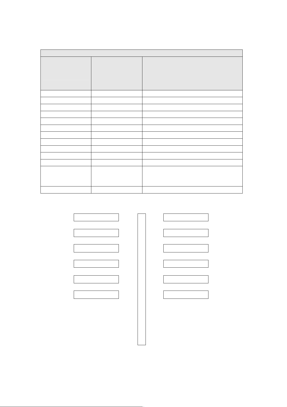
2.4 ES-3 (12 Horn / 1 Cable)
CABLE 1
Length of individual wires from
Horn Number
& Amplifier
Wire
Identification
Numbers
the point where the outer sheath
of the multi-core cable is
terminated.
(mm)
1/Amp 1 1 & 2 240 (Loom in cable loom 1)
2/Amp 1 3 & 4 880 (Loom in cable loom 1)
3/Amp 1 5 & 6 1520 (Loom in cable loom 1)
4/Amp 3 7 & 8 2160 (Loom in cable loom 1)
5/Amp 3 9 & 10 2800 (Loom in cable loom 1)
6/Amp 3 11 & 12 3440 (Loom in cable loom 1)
7/Amp 2 13 & 14 240 (Loom in cable loom 2)
8/Amp 2 15 & 16 880 (Loom in cable loom 2)
9/Amp 2 17 & 18 1520 (Loom in cable loom 2)
10/Amp 4 19 & 20 2160 (Loom in cable loom 2)
11/Amp 4 21 & 22 2800 (Loom in cable loom 2)
23 & 24
12/Amp 4
(Plus unused
3440 (Loom in cable loom 2)
wires
Horn 07
Horn 08
Horn 09
Horn 10
Horn 11
Horn 12
Horn 01
Horn 02
Horn 03
Horn 04
Horn 05
Horn 06
ES-3 Horn Arrangement
SG001a Issue 1 6 of 32 Apr 07
Page 8
KLAXON SIGNALS
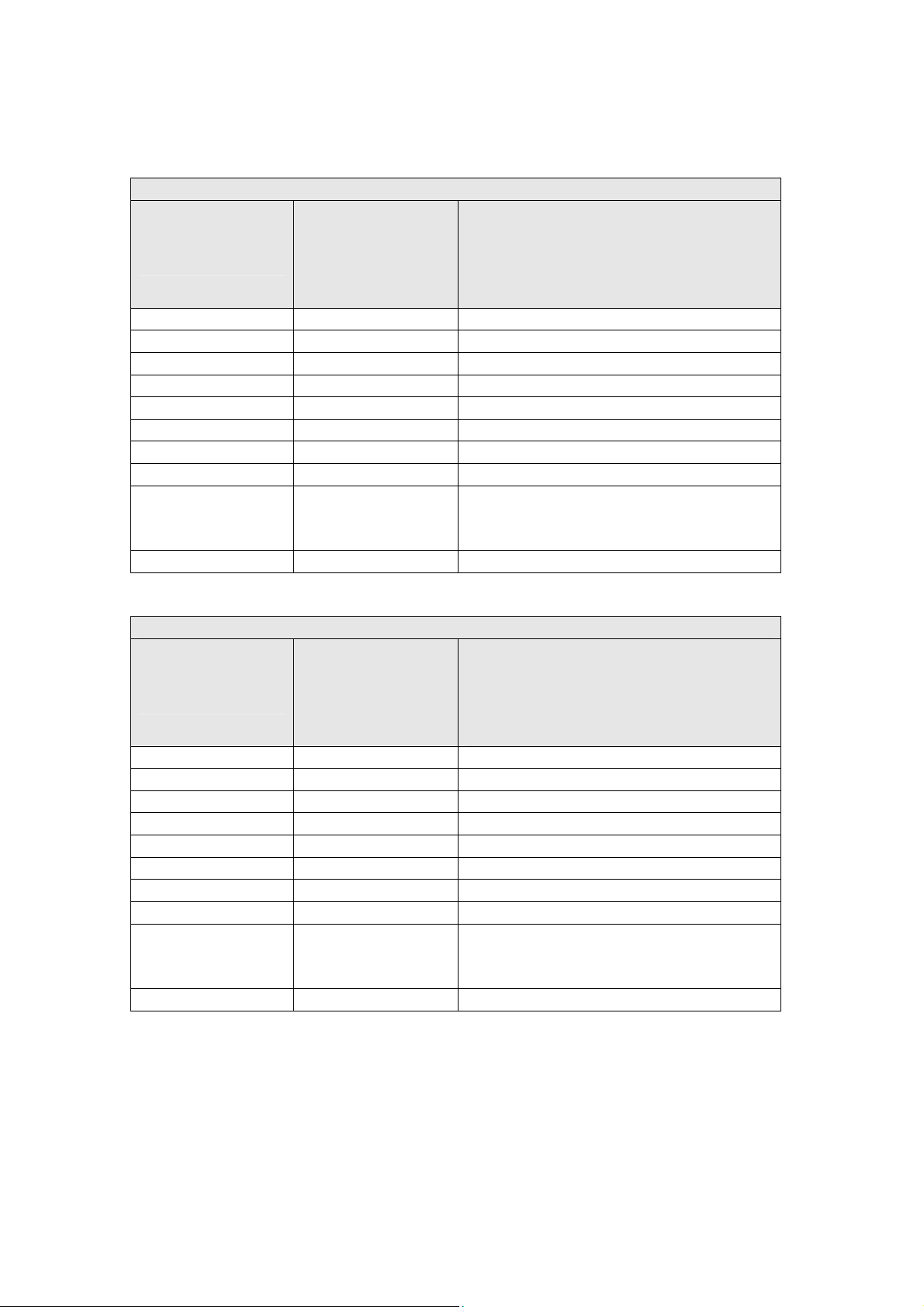
2.5 ES-4 (18 Horn / 2 Cable)
CABLE 1
Length of individual wires from
Horn Number
& Amplifier
Wire
Identification
Numbers
the point where the outer sheath
of the multi-core cable is
1/Amp 1 1 & 2 240
2/Amp 1 3 & 4 880
3/Amp 1 5 & 6 1520
4/Amp 3 7 & 8 2160
5/Amp 3 9 & 10 2800
6/Amp 3 11 & 12 3440
7/Amp 5 13 & 14 4080
8/Amp 5 15 & 16 4720
17 & 18
9/Amp 5
(Plus unused
wires
CABLE 2
Length of individual wires from
Horn Number
& Amplifier
Wire
Identification
Numbers
the point where the outer sheath
of the multi-core cable is
1/Amp 2 1 & 2 240
2/Amp 2 3 & 4 880
3/Amp 2 5 & 6 1520
4/Amp 4 7 & 8 2160
5/Amp 4 9 & 10 2800
6/Amp 4 11 & 12 3440
7/Amp 6 13 & 14 4080
8/Amp 6 15 & 16 4720
17 & 18
9/Amp 6
(Plus unused
wires
terminated.
(mm)
5360
terminated.
(mm)
5360
SG001a Issue 1 7 of 32 Apr 07
Page 9
KLAXON SIGNALS
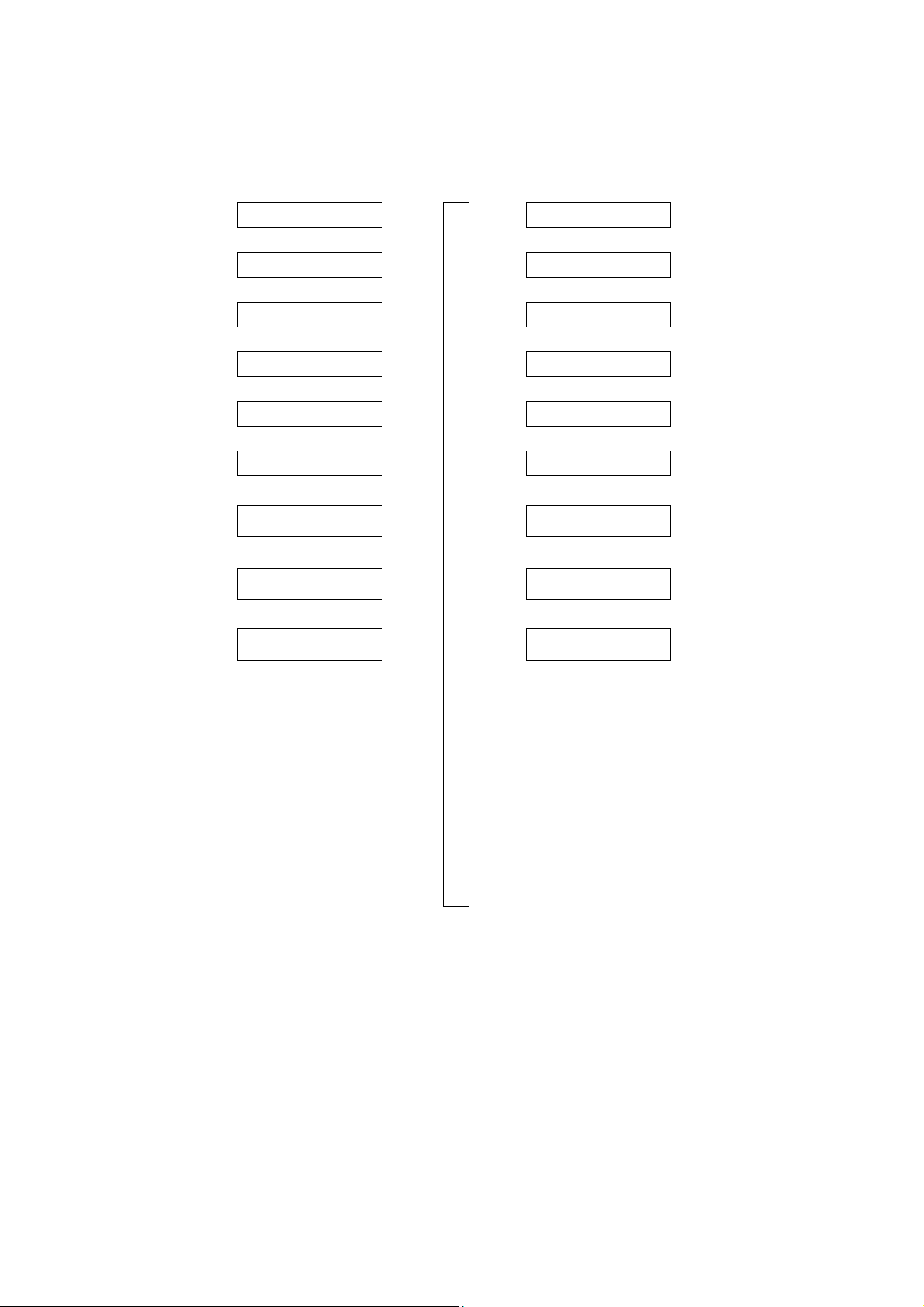
Horn 10
Horn 11
Horn 12
Horn 13
Horn 14
Horn 15
Horn 01
Horn 02
Horn 03
Horn 04
Horn 05
Horn 06
Horn 16
Horn 07
Horn 17
Horn 08
Horn 18
Horn 09
ES-4 Horn Arrangement
SG001a Issue 1 8 of 32 Apr 07
Page 10
KLAXON SIGNALS
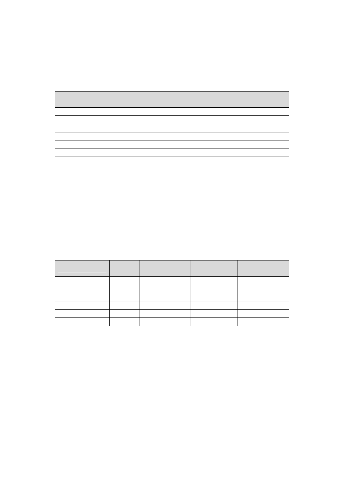
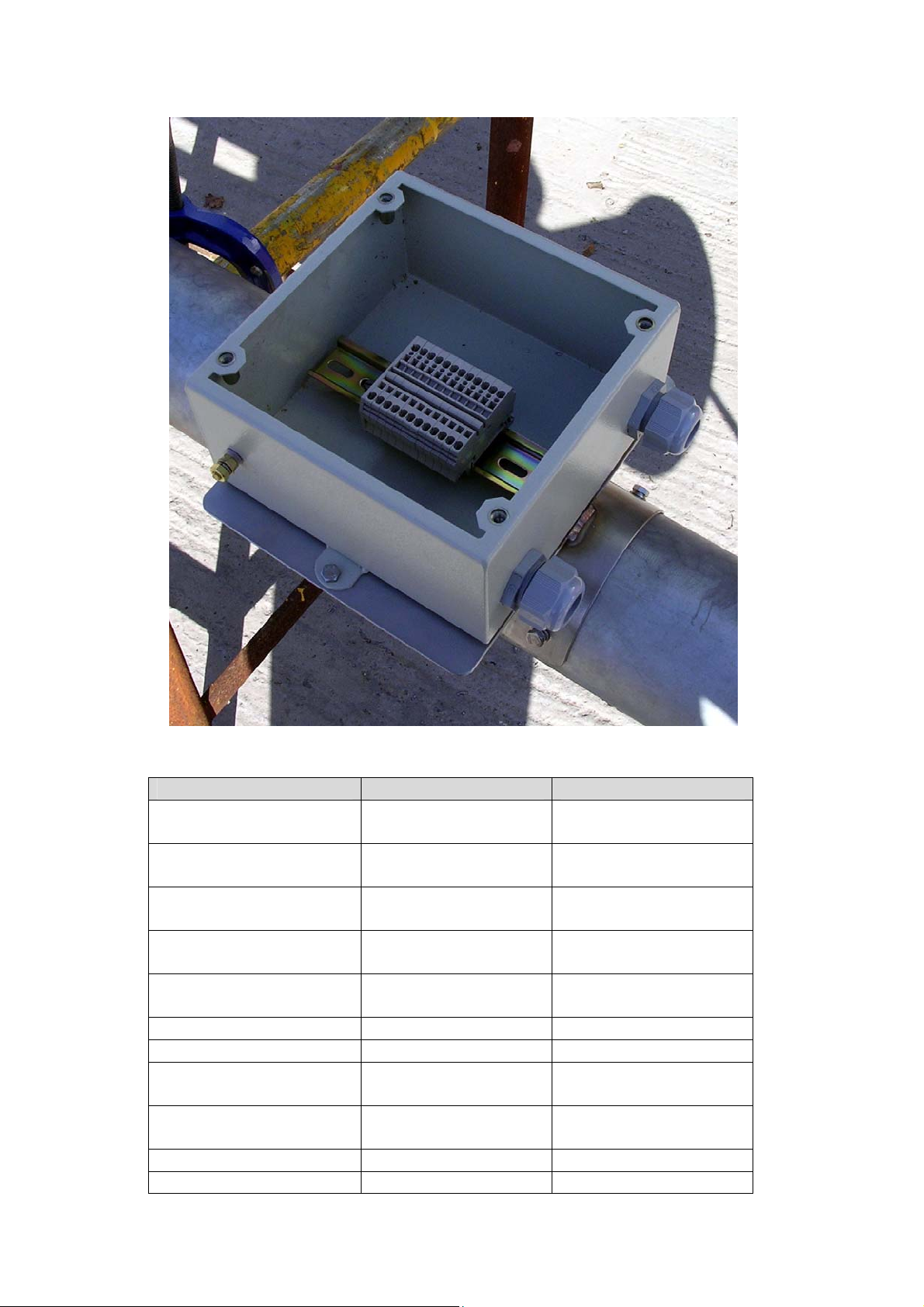
3. CABLE JUNCTION BOX ASSEMBLY INSTRUCTIONS
1. Select the correct enclosure for use as a cable junction box and
associated mounting bracket.
Siren Type Enclosure
Turbo 2 190mm x 190mmx 100mm Small
Turbo 3 190mm x 190mmx 100mm Small
ES-2 190mm x 190mmx 100mm Small
ES-3 250mm x 200mmx 100mm Large
ES-4 250mm x 200mmx 100mm Large
2. Cut a length of top hat section DIN rail to fit the enclosure and fit
using screws and nuts supplied with the enclosure.
3. Drill holes in enclosure for the attachment of cable glands. The
number and type are as specified in the table below. For a one cable
siren assembly two cable glands will be required in the side face of
the unit either side of the DIN rail strip. For a two cable assembly two
further cable glands would be required on the opposite face of the
enclosure to the first two cable glands.
Siren Type
No of
Glands
Gland Size
(mm)
Turbo 2 2 9.0 15.5 4
Turbo 3 4 9.0 15.5 6
ES-2 2 21.0 29.0 12
ES-3 2 21.0 29.0 24
ES-4 4 21.0 29.0 36
Enclosure Mounting
Bracket
Hole Size
(mm)
Connectors
No of
SG001a Issue 1 9 of 32 Apr 07
Page 11
KLAXON SIGNALS
3.1 PURCHASED COMPONENTS
COMPONENT ADDITIONAL INFO PART No
Enclosure 190mm x
190mmx 100mm
Enclosure 250mm x
200mmx 100mm
2.5mm Screwless Feed
Through Connectors
Enclosure Mounting
Bracket Small
Enclosure Mounting
Bracket Large
For use on Turbo 2/3
& ES2 Sirens
For use on ES3 &
ES4 Sirens
18-186678
RS 174-820
18-186679
RS 174-836
5 per pack RS 225-9894
For use on Turbo 2/3
& ES2 Sirens
For use on ES3 &
ES4 Sirens
18-186209
18-186210
Connector End Cover 5 per pack RS 225-9923
End Supports 5 per pack RS 821-633
Din Rail (Top Hat
section Punched)
Blank Terminal
Markers
1 Metre Length RS 606-838
RS 425-409
7-13mm Cable Gland 5 per pack RS 365-8438
11-21mm Cable Gland 5 per pack RS 362-0001
SG001a Issue 1 10 of 32 Apr 07
Page 12
KLAXON SIGNALS
4. MAST ASSEMBLY INSTRUCTIONS
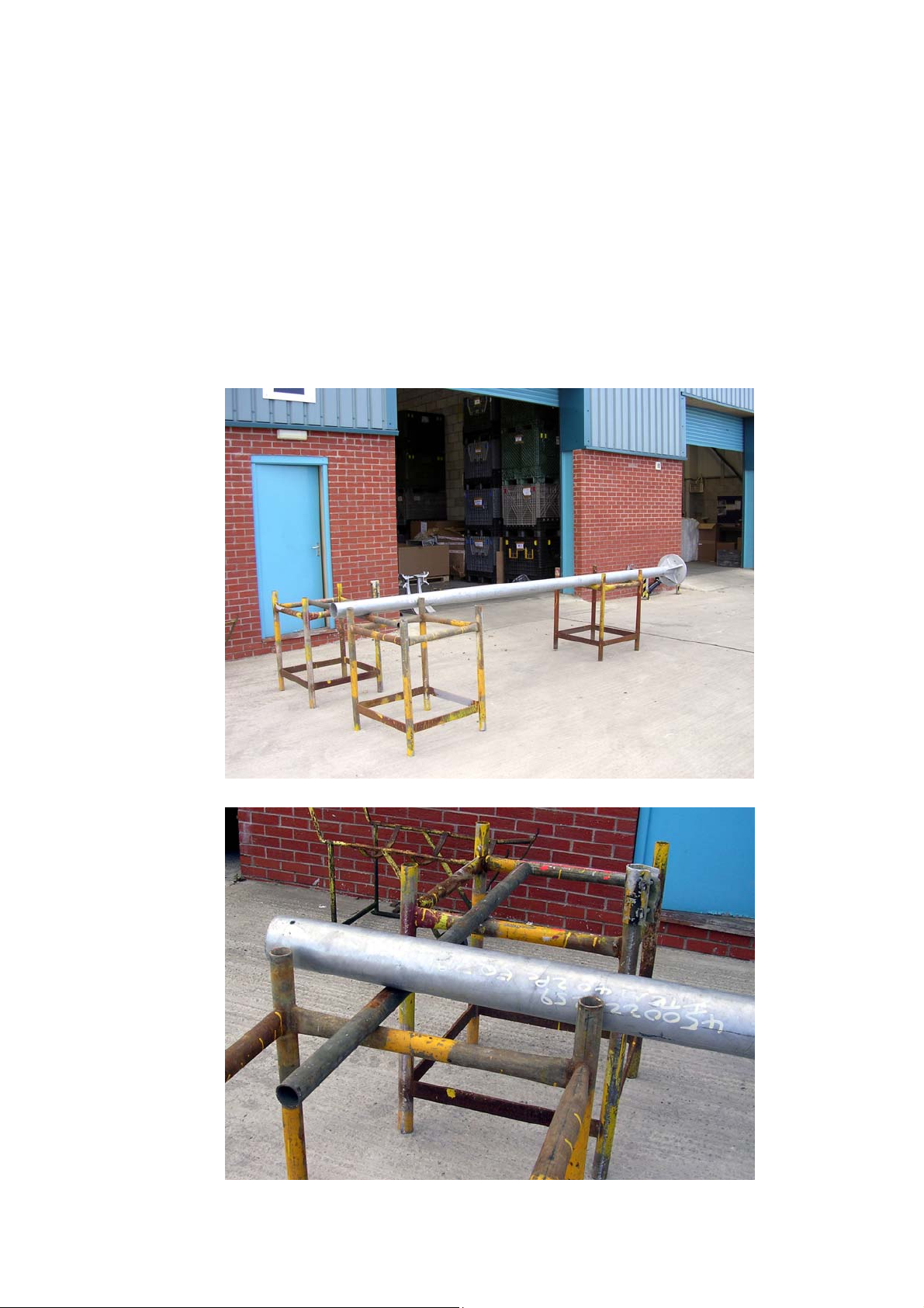
1. Support the mast during the attachment of the horn units in a
horizontal position approximately 1 metre off the ground by the use of
three suitable load bearing trestles and a support beam. The trestles
are to be deployed in the following manner.
At the base end of the mast position one trestle and at the other end
position the remaining two trestles, one at either side with a support
beam between them on which the mast is supported. This support
beam should be between 500 – 600 mm from the end of the mast.
SG001a Issue 1 11 of 32 Apr 07
Page 13
KLAXON SIGNALS
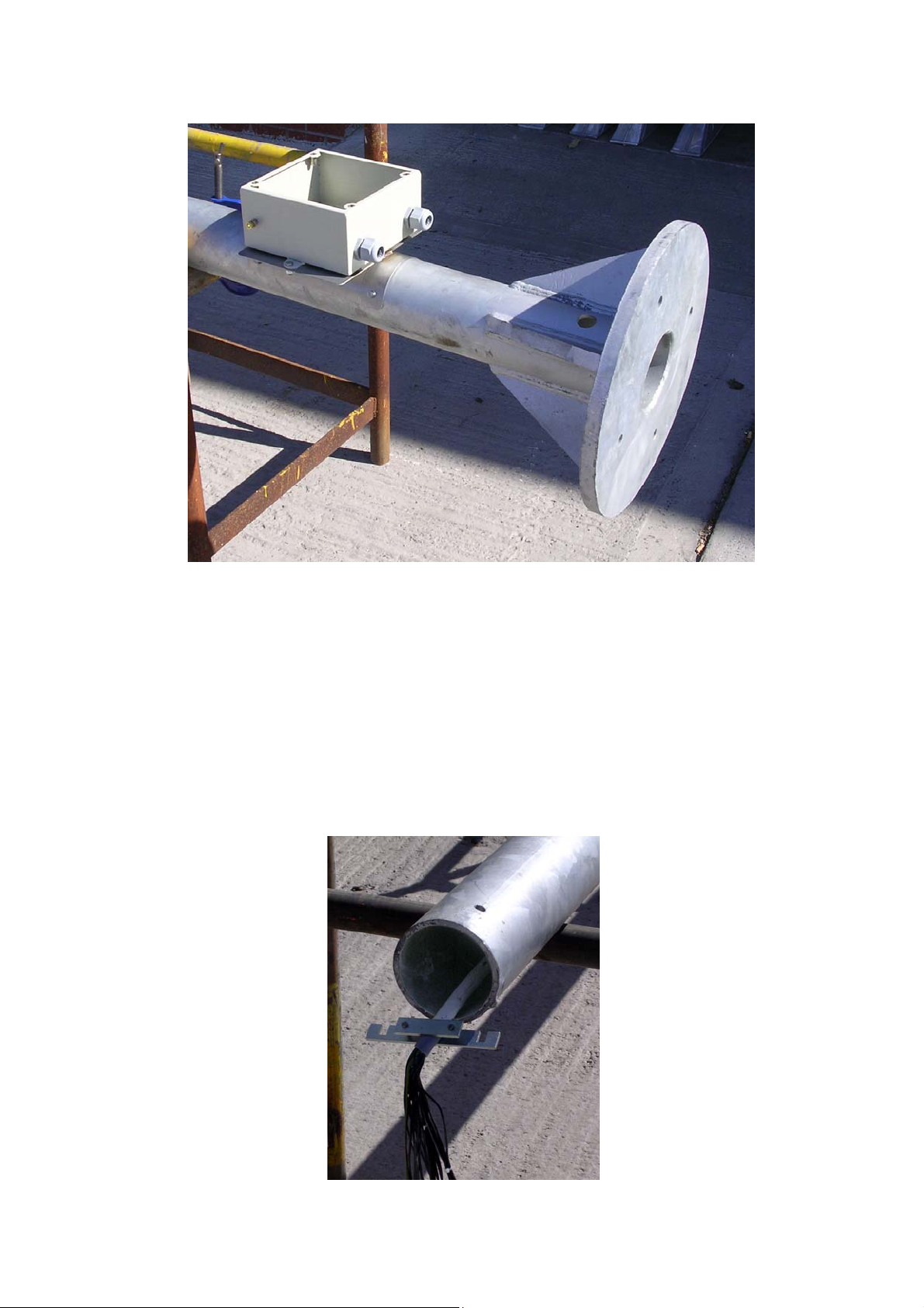
2. Prepare the mast for the fitting of the cable junction box and
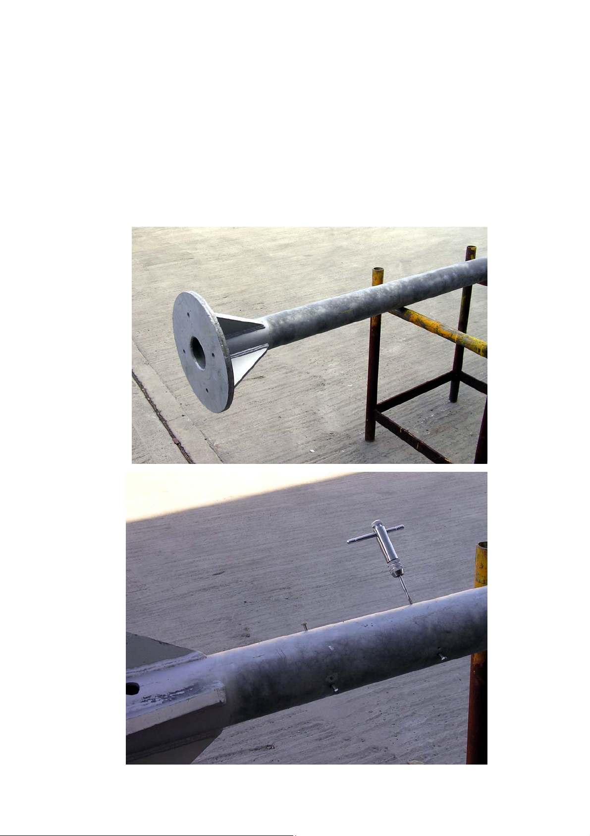
attachment bracket by positioning the bracket at a convenient height
above the base of the mast and carefully marking on the mast the
position of the bracket mounting holes.
Remove the bracket and using a 5.0 mm drill bit, drill the four
mounting holes and then tap with an M6 thread.
Attach the bracket to the mast using four M6 x 15mm bolts and then
attach the junction box to the bracket using two M6 x 15mm bolts and
associated nuts and washers.
SG001a Issue 1 12 of 32 Apr 07
Page 14
KLAXON SIGNALS
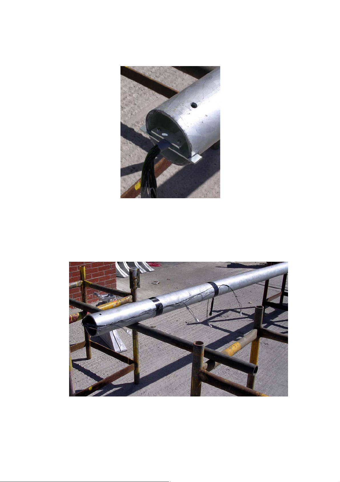
3. Pass the previously prepared multi-core horn driver cable(s) through
the inside of the mast. The end of the cable with the connectors to be
connected to the siren horn drivers to exit the mast at the top.
4. Identify the multi-core cables if more than one by the use of either a
red or blue identification marker or tape applied to the outer sheath at
both ends of the cables.
5. Attach the cabling restraint bracket to the cable(s) at the top of the
mast at a point approximately 15mm below from where the outer
sheaths of the cable(s) are terminated.
SG001a Issue 1 13 of 32 Apr 07
Page 15
KLAXON SIGNALS
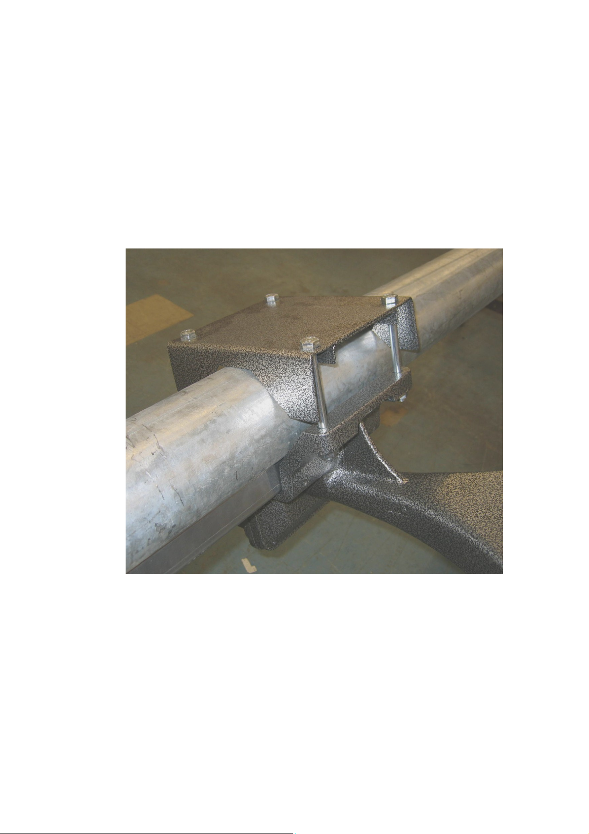
6. Pull the cable(s) from down from the bottom of the mast until the
cable support bracket seats neatly in the mast.
7. Temporarily tape the made off ends of the siren driver cables down
their respective sides of the mast, roughly in the position they would
be when the assembly is complete.
SG001a Issue 1 14 of 32 Apr 07
Page 16
KLAXON SIGNALS
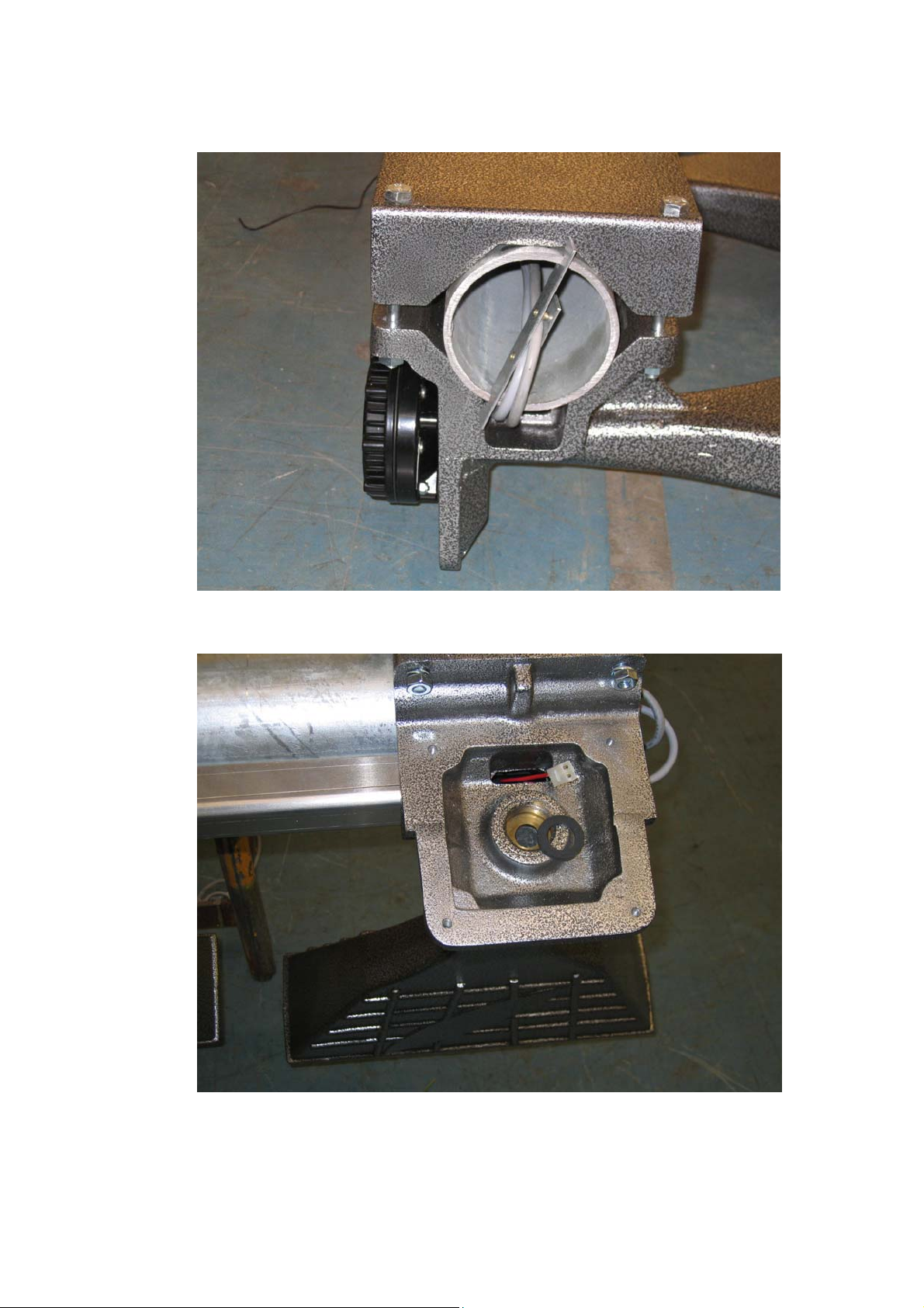
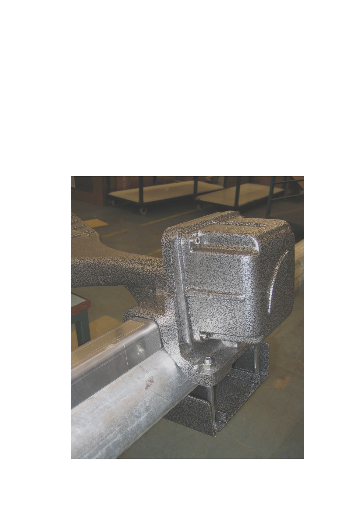
8. Secure the first horn or pair of horns to the top of the mast using four
M10 bolts and associated nuts, spring and plain washers, (facing in
opposite directions for omni-directional use and facing in the same
direction for uni-directional use), remembering also to attach the mast
cover mounting brackets at the same time. (These mounting brackets
are held in place by the top two horn assembly to mast fixing bolts).
When secured in position thread the appropriate driver wires and
associated connectors into the horn assemblies via the holes
provided in the horn assembly flanges.
Note: Omni-directional horn assembly depicted in the picture above.
SG001a Issue 1 15 of 32 Apr 07
Page 17
KLAXON SIGNALS
SG001a Issue 1 16 of 32 Apr 07
Page 18
KLAXON SIGNALS
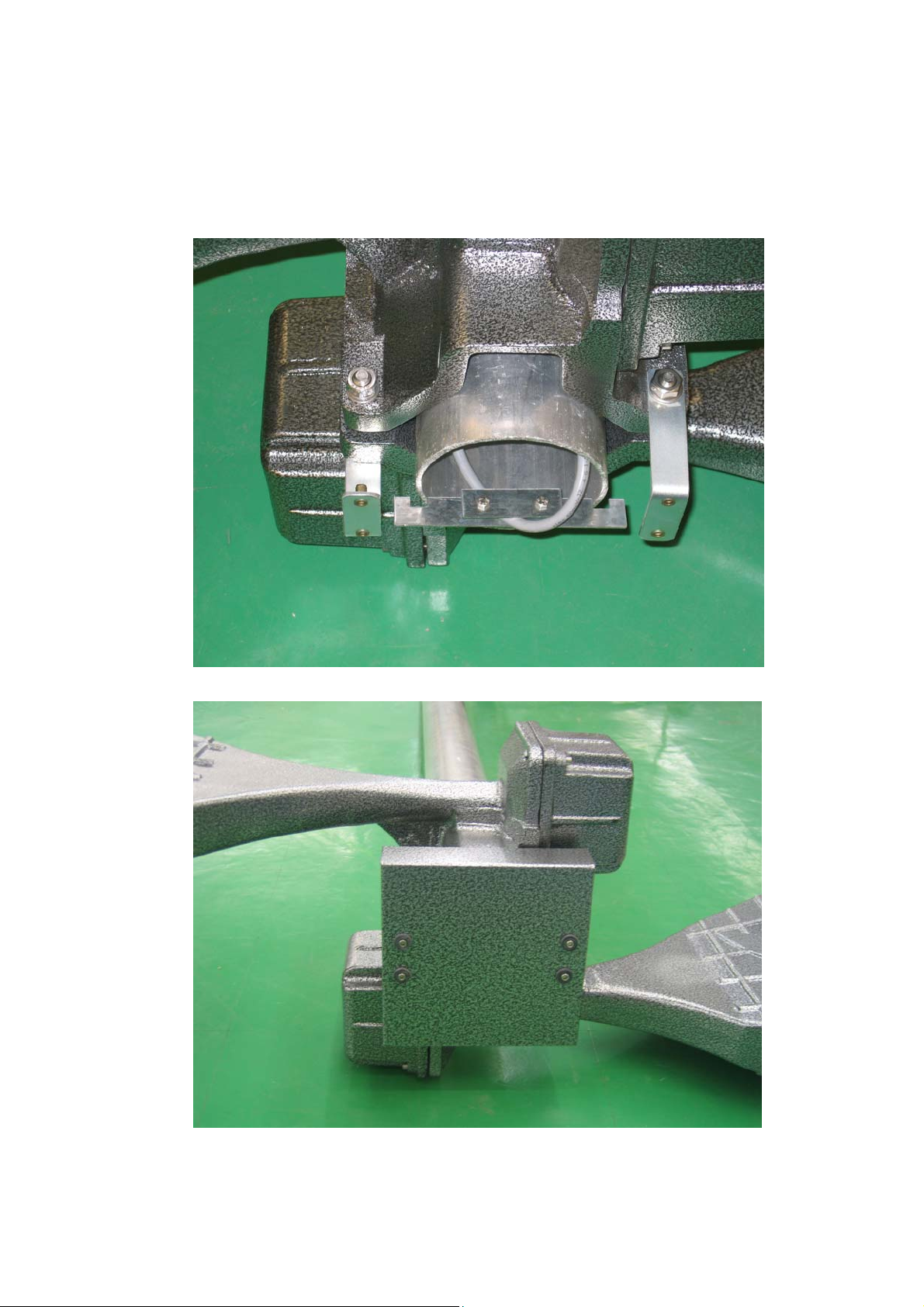
9. Repeat the process of adding horn assemblies down the mast by
initially securing the horn assemblies loosely around the mast before
inserting the U-shaped cable protection covers between the horn
assemblies. Then using a mallet gently tap the loosely attached siren
assembly pairs into position and align with previously fitted horn
assembly prior to securing firmly.
Recheck the horn alignment when the assembly is securely
positioned and if necessary adjust securing bolts to attain the correct
alignment.
Note: Ensure the cabling does not become pinched by the horn
assembly flanges or cable covers.
SG001a Issue 1 17 of 32 Apr 07
Page 19
KLAXON SIGNALS
10. Secure the mast top cover to the brackets on the uppermost horn
assembly using four M8 x 15mm bolts and washers.
SG001a Issue 1 18 of 32 Apr 07
Page 20
KLAXON SIGNALS
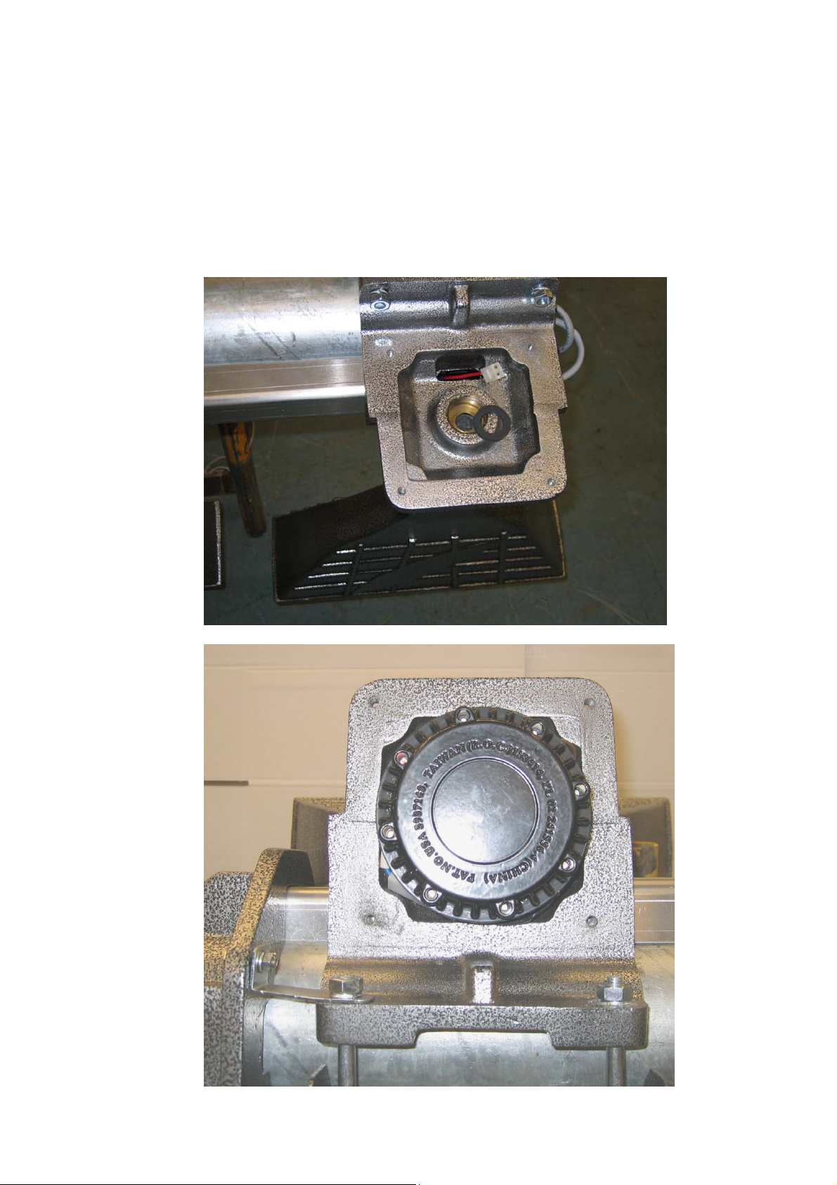
11. Carefully screw the sounder driver units into the horn assemblies
ensuring that at least one O ring rubber sealing gasket is used,
against which the driver is firmly hand tightened. When tightened the
driver water drainage hole must be positioned in the vertical plane
towards the base of the mast. (If this is not possible with the gasket
used, then change the gasket for either a thicker or thinner one.
1.5mm or 3.0mm).
SG001a Issue 1 19 of 32 Apr 07
Page 21
KLAXON SIGNALS
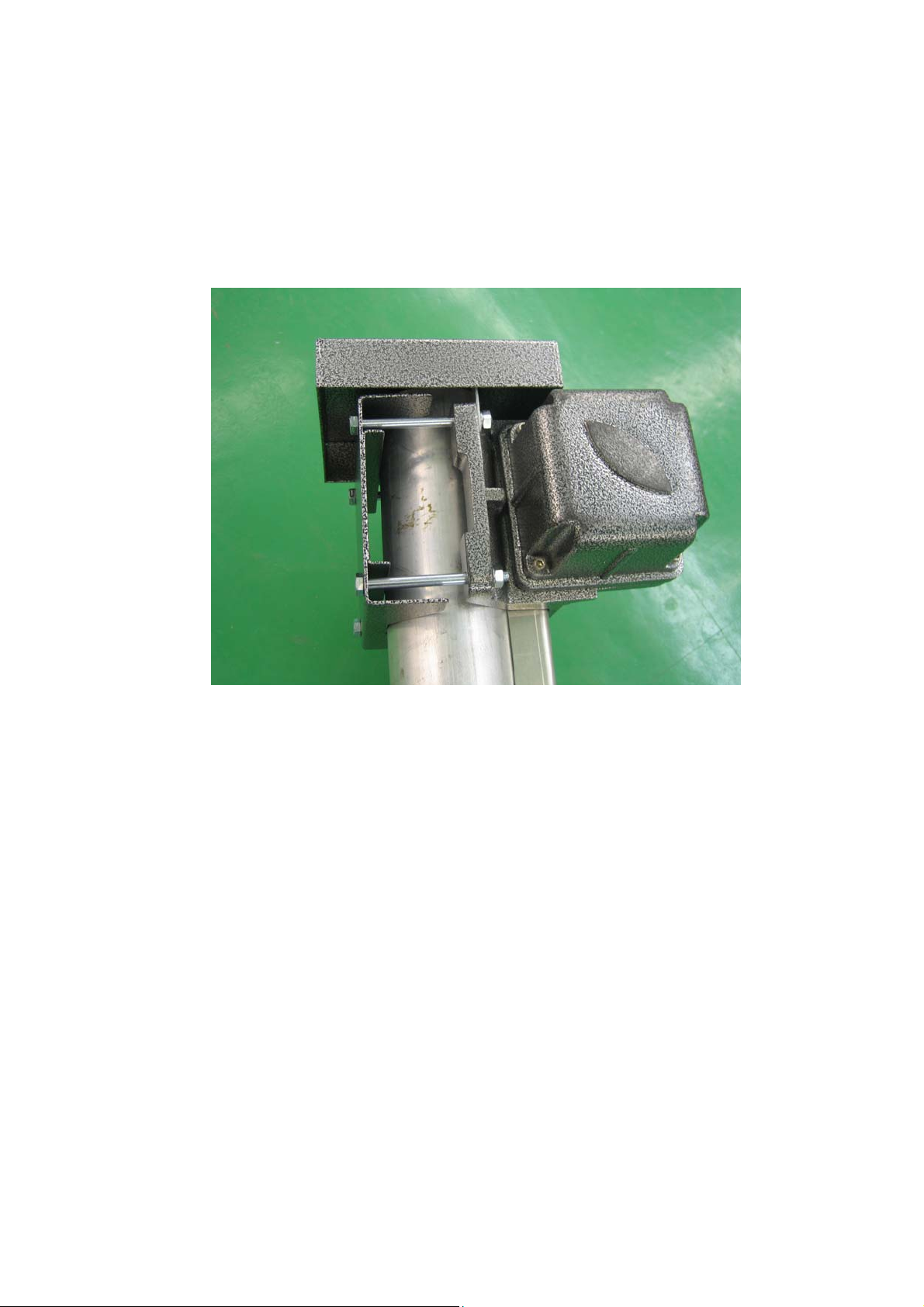
12. Attach the driver cable connectors to the driver connectors and then
carefully position the connectors under the driver. When this is done
secure the driver covers to the horn assemblies using four M4 x
30mm Allen key bolts.
13. Identify which horns are connected to which cable by the use of either
a red or blue identification marker as appropriate applied to the outer
case of each horn driver cover.
SG001a Issue 1 20 of 32 Apr 07
Page 22
KLAXON SIGNALS
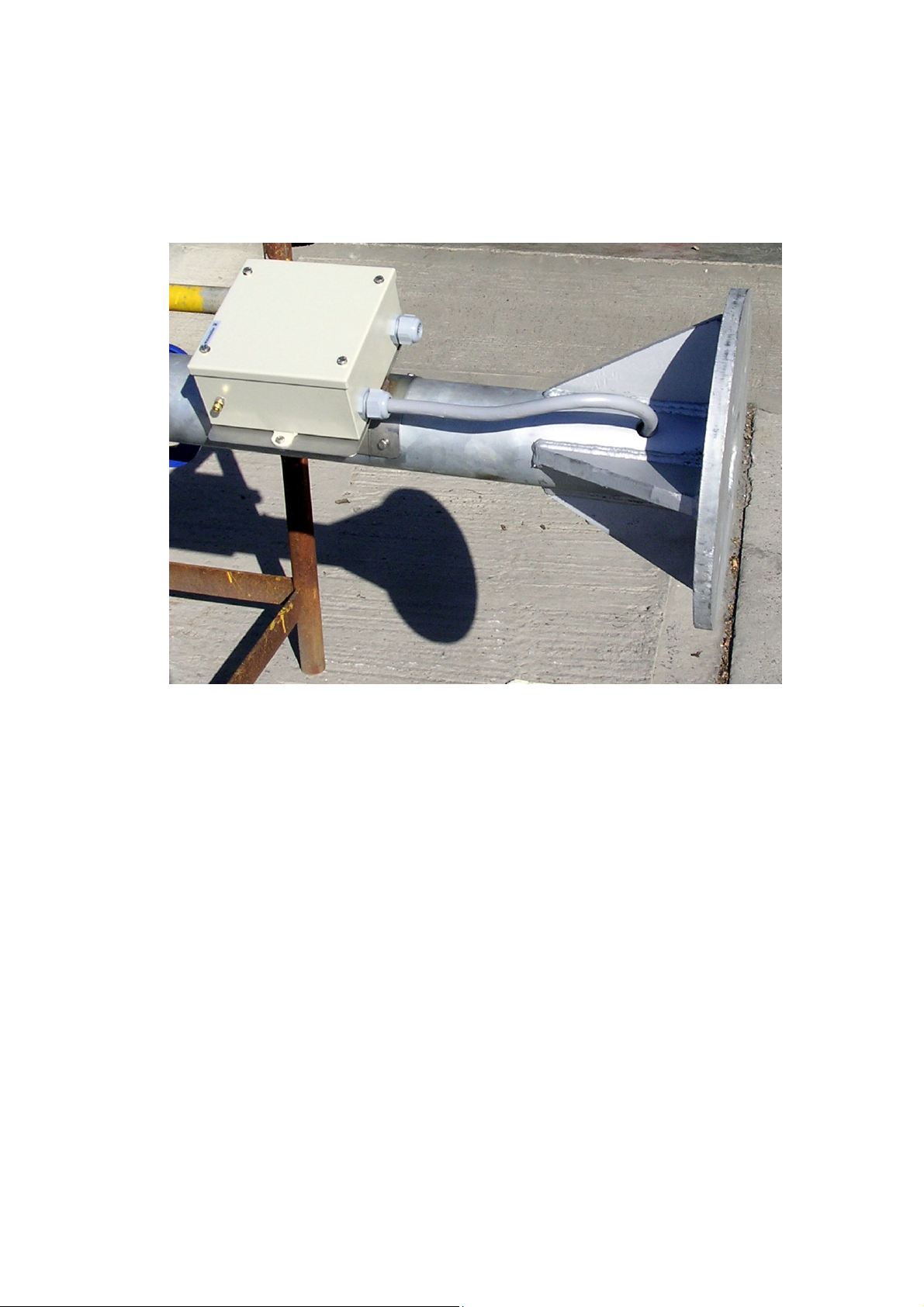
14. At the base of the mast feed the cable(s) that are exiting at the base
through the holes in the sides of the mast approximately 100mm
above the base.
15. Feed the cable(s) into the cable junction through an appropriate
gland, cut to size and inserting into the feed through connectors
contained in the junction box.
Remember to keep the cable identification marking.
SG001a Issue 1 21 of 32 Apr 07
Page 23
KLAXON SIGNALS
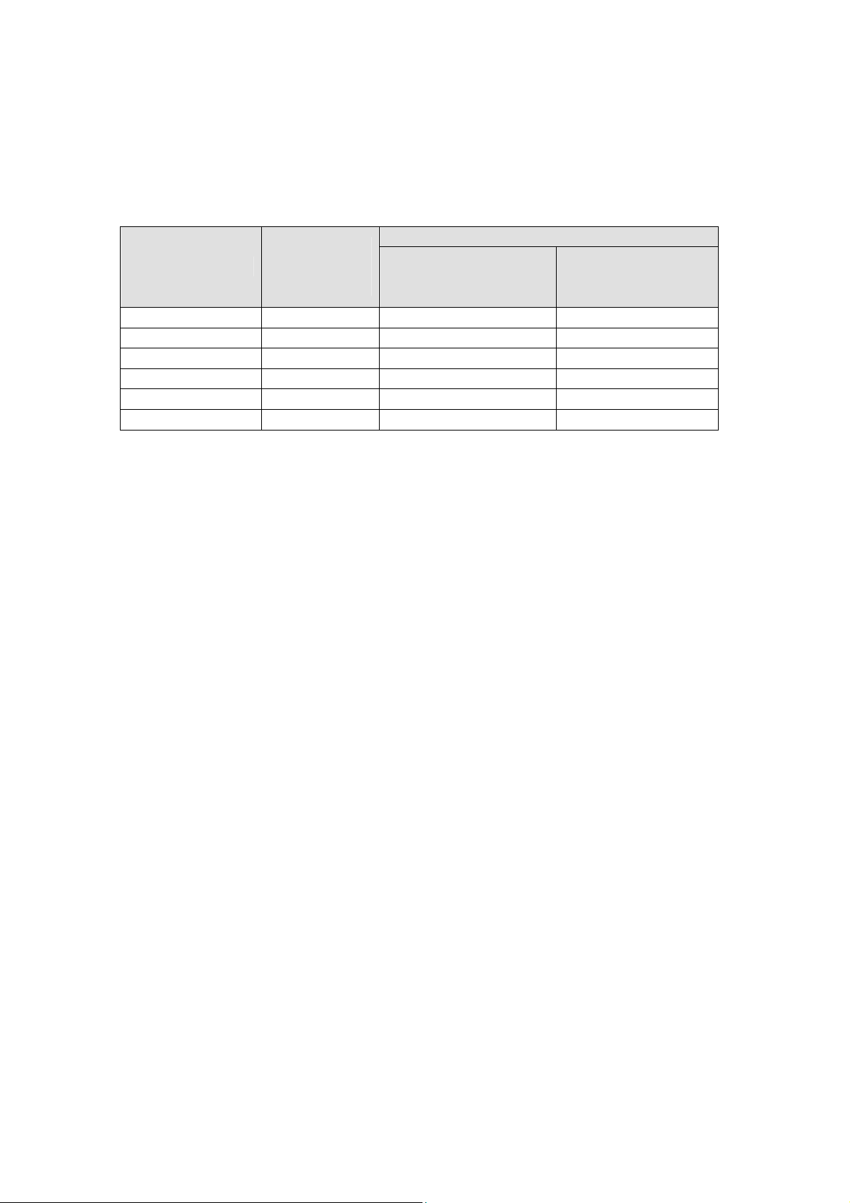
5. HORN ARRAY DIMENSIONS & WEIGHT
Horn Array
Siren Type
Turbo 2 27 1012 x 500 x 430 730 x 1000 x 430
Turbo 3 41 - 730 x 1500 x 430
ES-2 82 1012 x 1500 x 430 730 x 1500 x 430
ES-3 162 1012 x 3000 x 430 730 x 3000 x 430
ES-4 243 1012 x 4500 x 430 730 x 4500 x 430
Note: Weight and dimensions listed does not include mast.
Weight
(Kg)
Omni-Directional
(WxHxD/mm)
Dimensions
Uni-directional
(WxHxD/mm)
6. HORN ASSEMBLY TESTING
Using a multi-meter measure the resistance between each pair of horn driver
conductors at the cable junction box and between each conductor and the
mast metalwork to ensure there are no cable breaks or trapped conductors.
The resistance measured between conductors should be in the region of 4.8
to 5.2 ohms and there should be no connection between the conductors and
the siren metalwork.
SG001a Issue 1 22 of 32 Apr 07
Page 24
KLAXON SIGNALS
7. STANDARD SIREN MAST INFORMATION
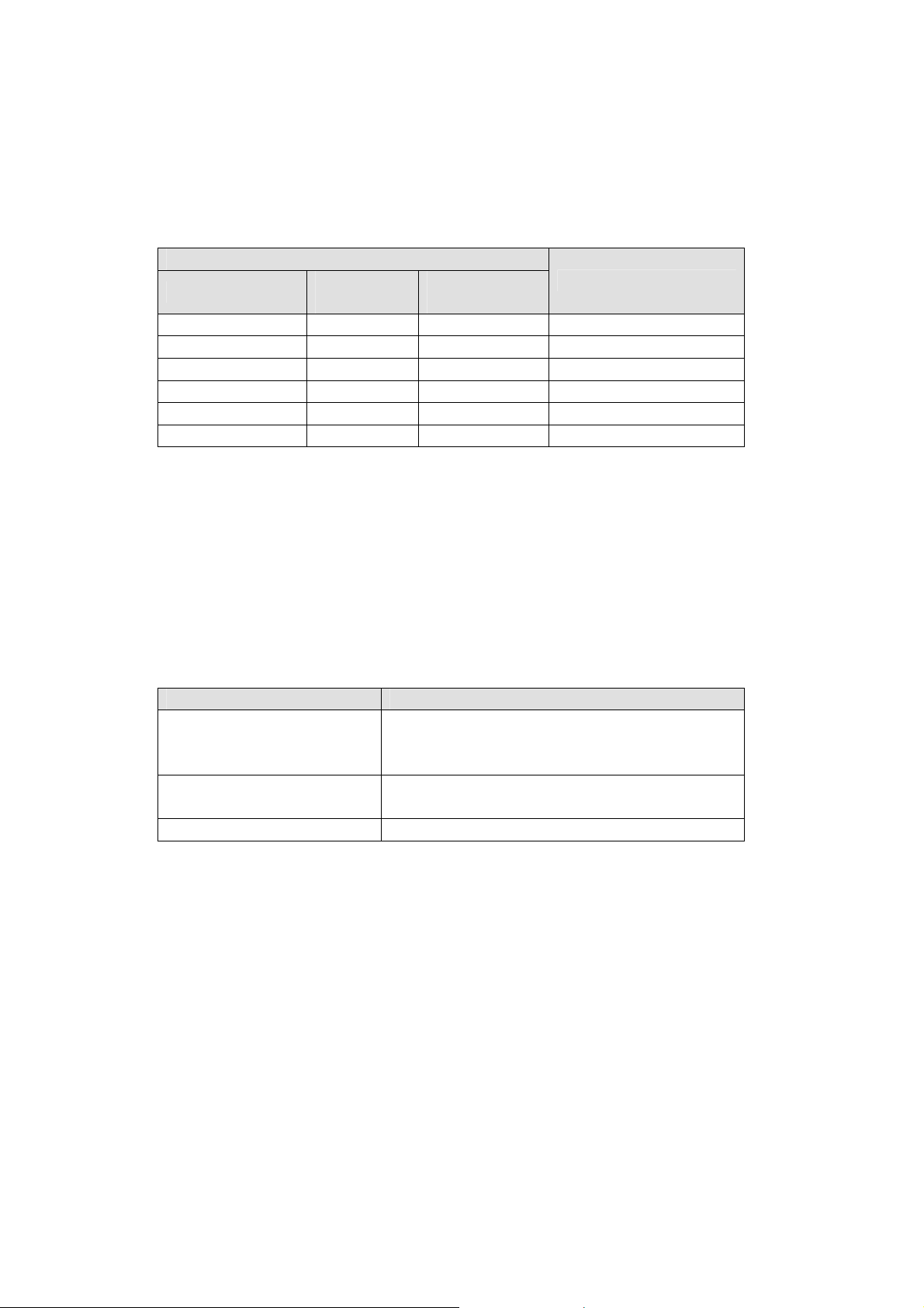
7.1 Mast Lengths, Weights and Number of Horns
MAST
Type
18-185938 50 3.0 Up to 6
18-185939 75 4.5 Up to 12
18-185940 100 6.0 Up to 18
18-185941 280 12.0 Support Mast Only
Note:
• Horn Masts are constructed from 114.3mm x 6 CHS galvanised
steel.
• Support Mast is constructed from 193.7mm x 5 CHS galvanised
steel.
Weight
(Kg)
Length
(metres)
No. of Horns
7.2 Mast Fixing Bolts
Function Mounting Bolts
Securing siren mast or
support mast to the
ground.
Securing siren mast to
support mast
7.3 Mast Base Construction
Typical base construction for a 12 metre support mast with siren horn mast
array mounted on top would be a concrete base of 2.1 x 1.5 x 0.8 metre
deep construction reinforced at the bottom with a layer of A393 mesh.
Note: The base construction suggested is only typical and each installation
will be required to be evaluated by the installer taking into consideration the
specific ground conditions where the mast is to be erected.
Medium carbon steel zinc plated grade
8.8, 20mm diameter, 300mm length
Medium carbon steel zinc plated grade
8.8, 20mm diameter, 75mm length
SG001a Issue 1 23 of 32 Apr 07
Page 25

KLAXON SIGNALS
7.4 Standard Mast Drawings
The following pages contain drawings of the standard siren masts and
support mast.
SG001a Issue 1 24 of 32 Apr 07
Page 26
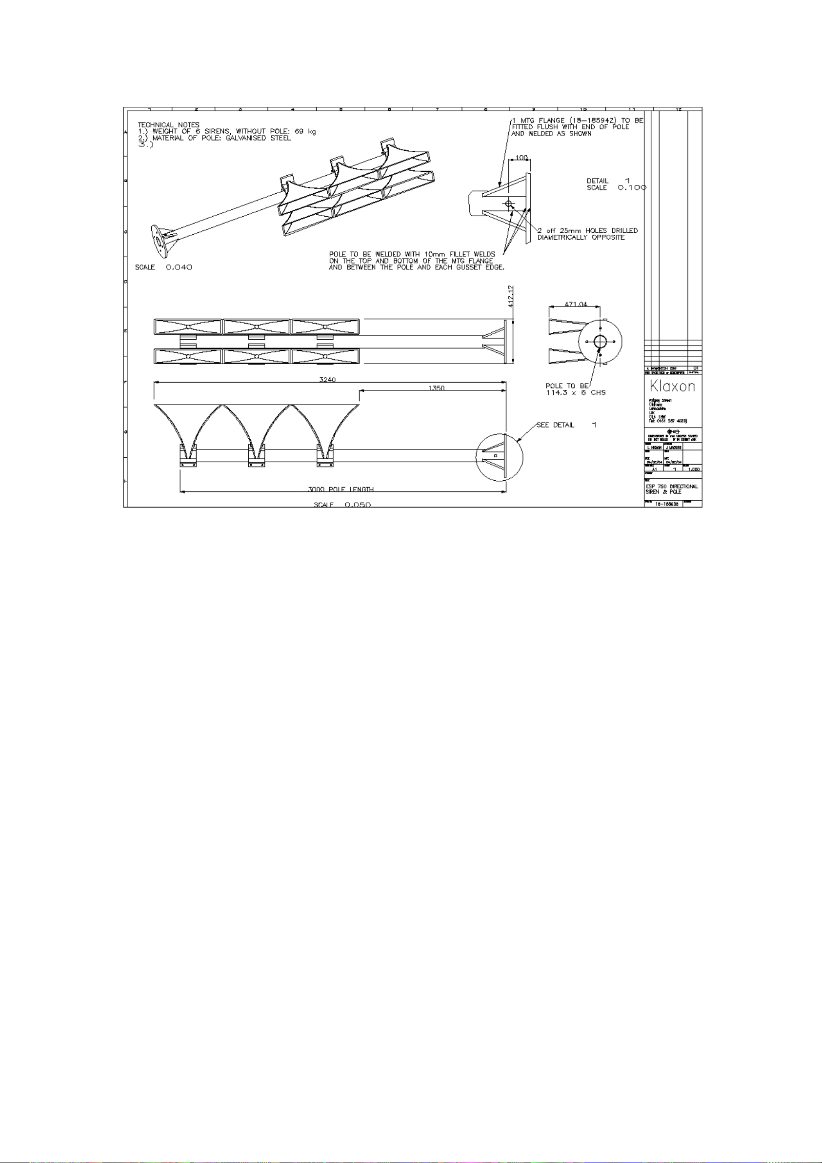
7.4.1 3 Metre Mast (18-185938)
KLAXON SIGNALS
SG001a Issue 1 25 of 32 Apr 07
Page 27
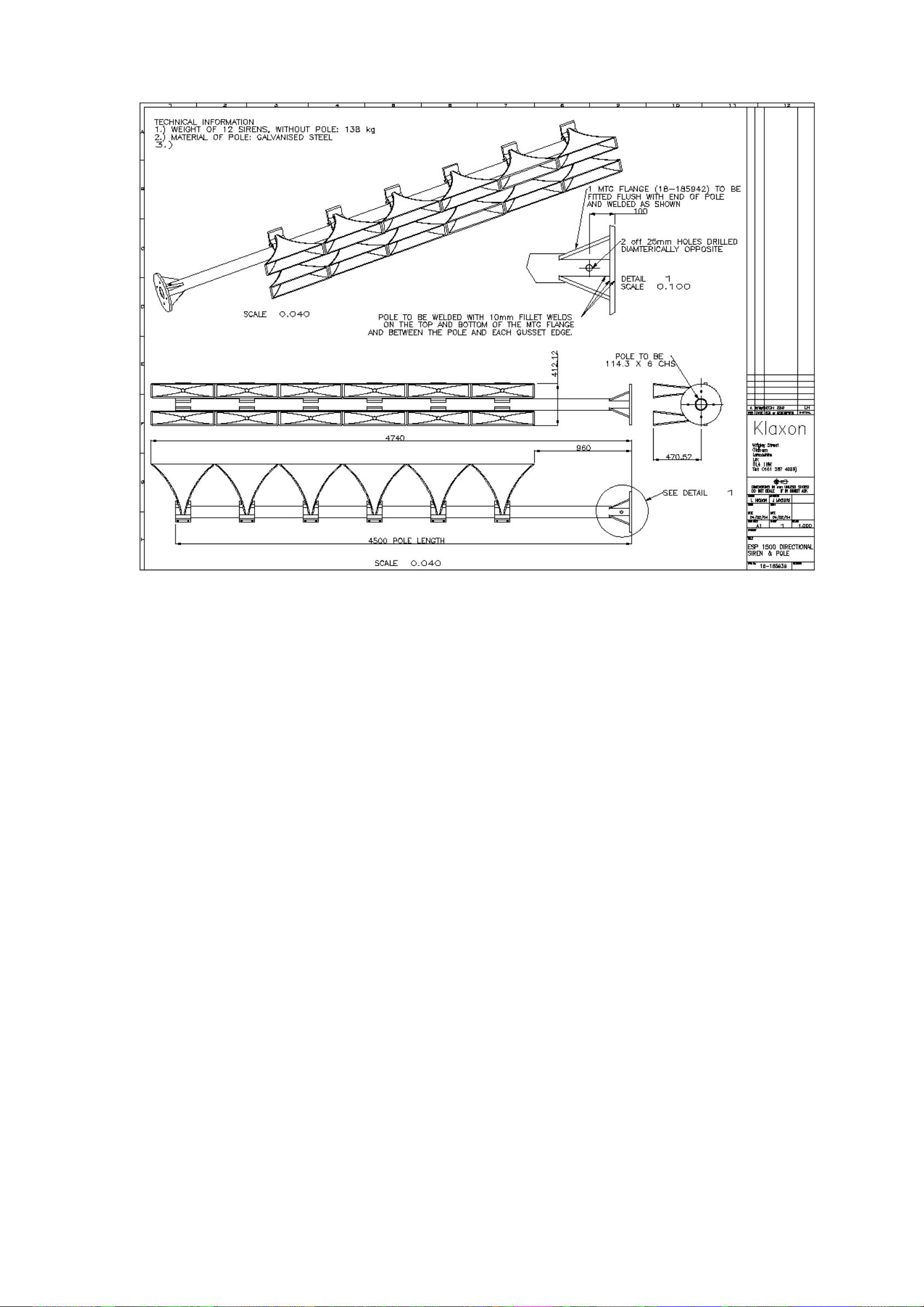
7.4.2 4.5 Metre Mast (18-185939)
KLAXON SIGNALS
SG001a Issue 1 26 of 32 Apr 07
Page 28
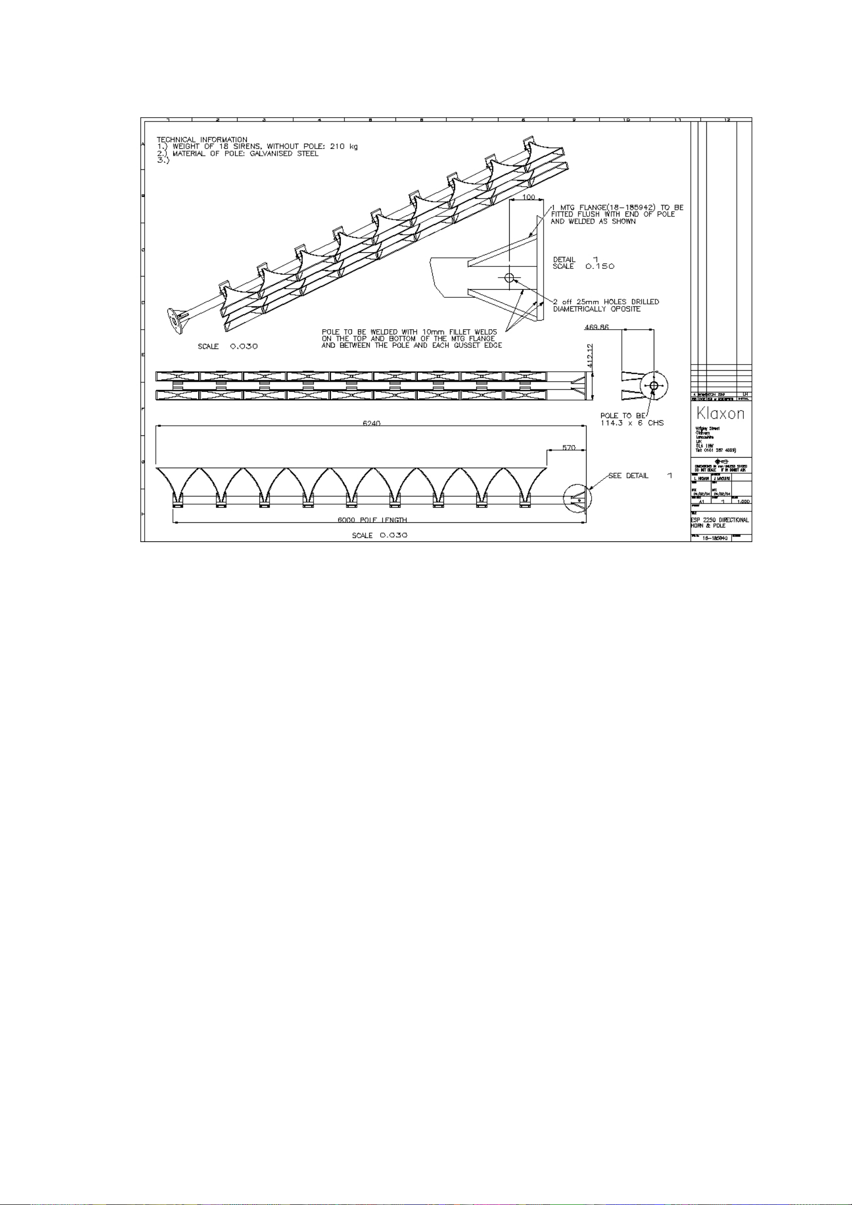
7.4.3 6 Metre Mast (18-185940)
KLAXON SIGNALS
SG001a Issue 1 27 of 32 Apr 07
Page 29
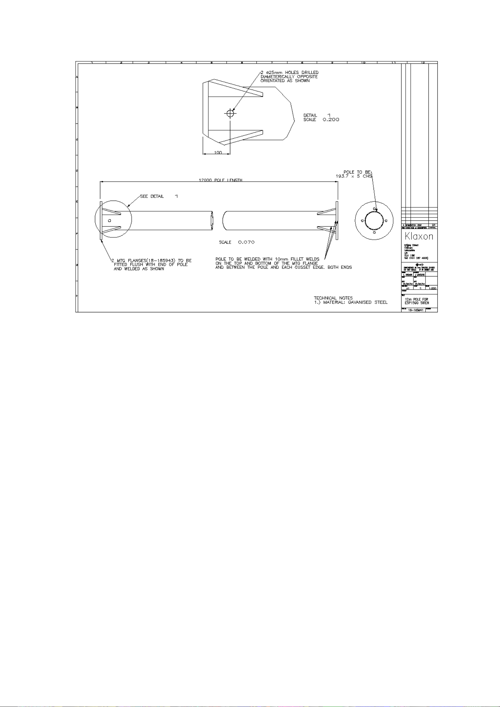
7.4.4 12 Metre Support Mast (18-185941)
KLAXON SIGNALS
SG001a Issue 1 28 of 32 Apr 07
Page 30
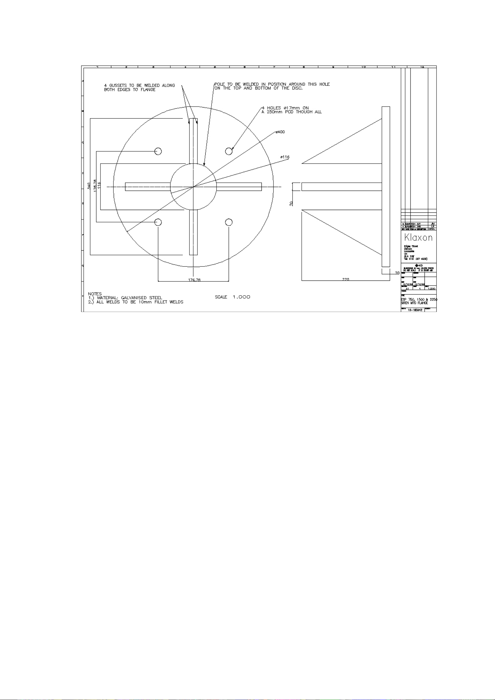
KLAXON SIGNALS
7.4.5 12 Metre Support Mast Mounting Flange 1 (18-185942)
SG001a Issue 1 29 of 32 Apr 07
Page 31
KLAXON SIGNALS
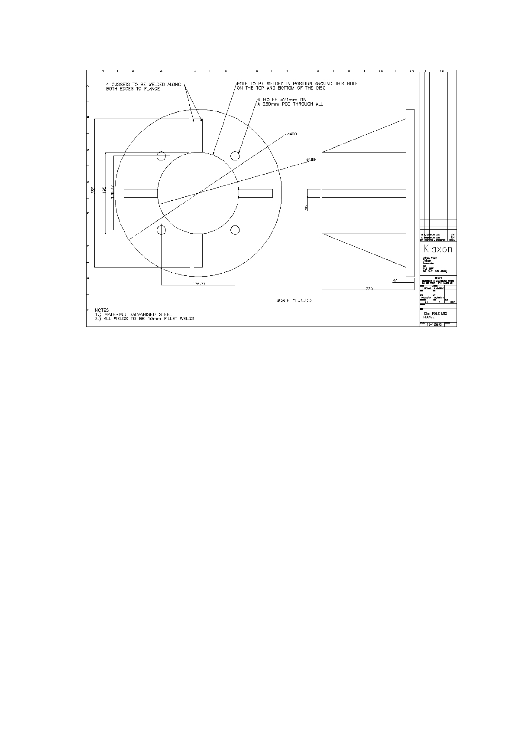
7.4.6 12 Metre Support Mast Mounting Flange 2 (18-185943)
SG001a Issue 1 30 of 32 Apr 07
Page 32
KLAXON SIGNALS
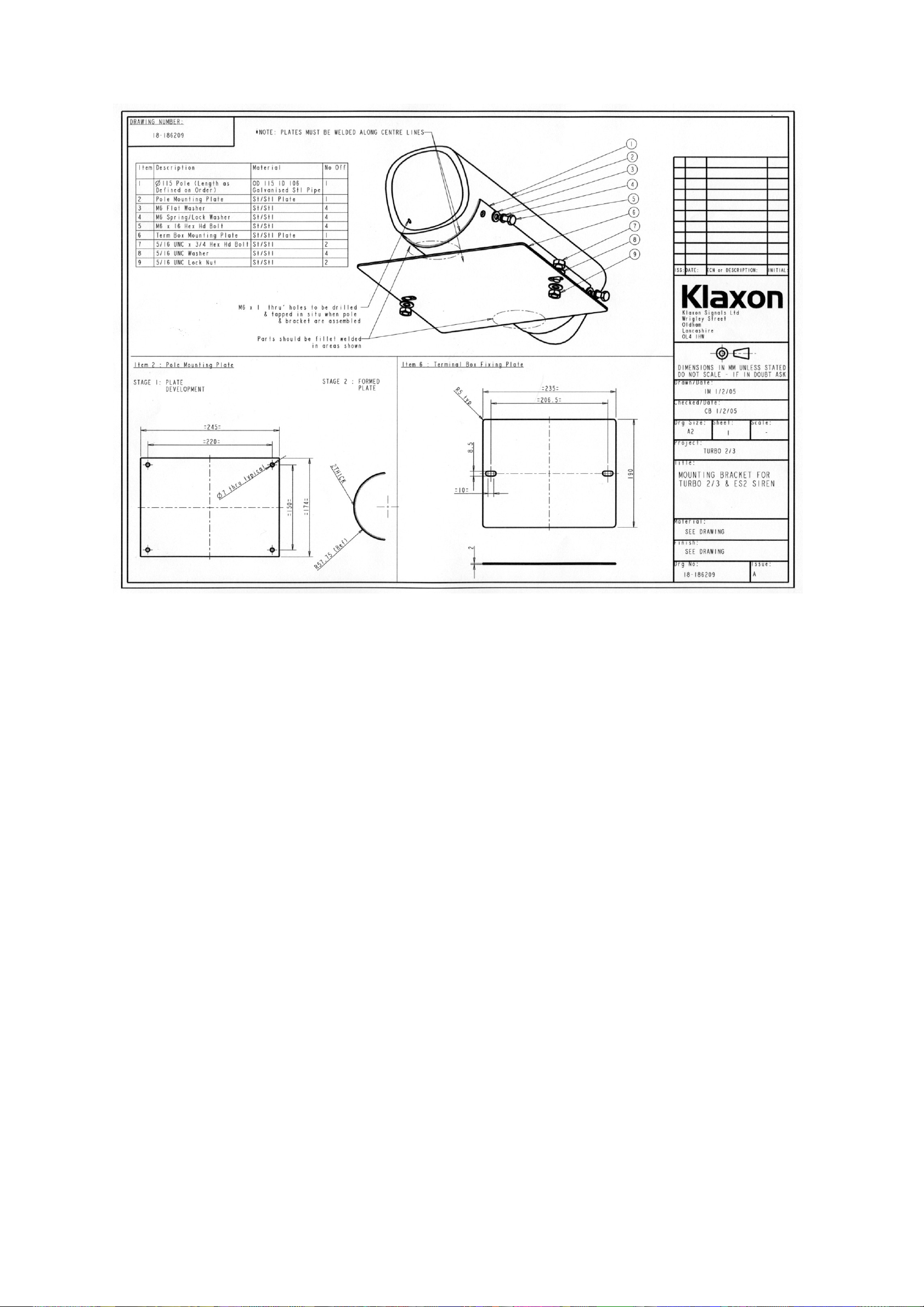
7.4.7 Turbo 2/3 & ES2 Siren Horn Cable Box Bracket (18-186209)
SG001a Issue 1 31 of 32 Apr 07
Page 33
KLAXON SIGNALS
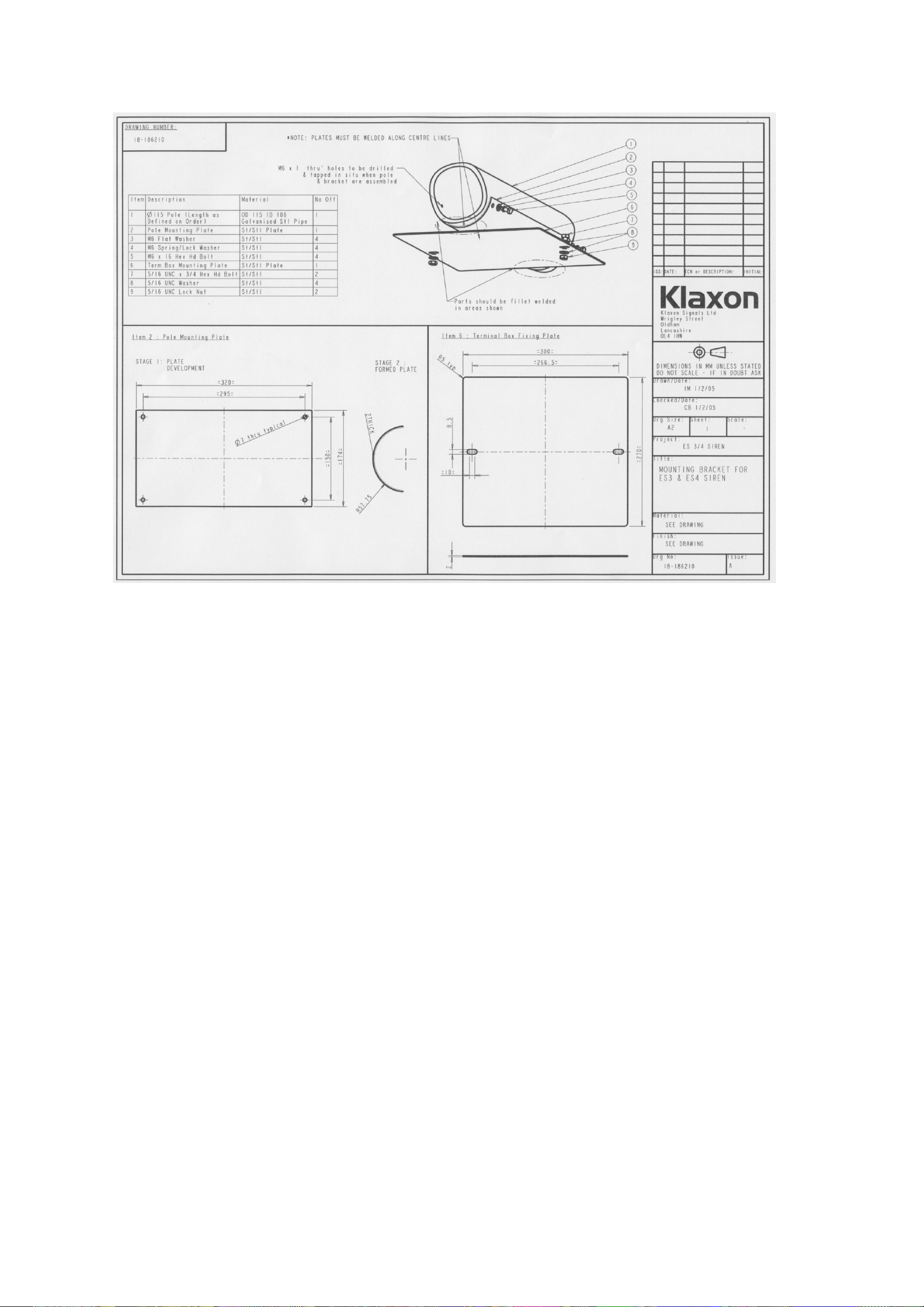
7.4.8 ES3 & ES4 Siren Horn Cable Box Bracket (18-186210)
SG001a Issue 1 32 of 32 Apr 07
 Loading...