

Klavis Mixwitch User Manual
V1.0
SUPPORT & ADDITIONAL INFO
The complete users manual is available on:
www.klavis.com/support
Contact us: modular@klavis.com
Copyright 2018 - Klavis Technologies s.a.
INSTALLATION
The Logica Gater is a Eurorack compliant module that requires the presence of a 5V supply.
Ensure that there is enough power left to supply this module.
Beware of the orientation; the stripe on the ribbon cable
should match a similar stripe for the –12 (minus 12 Volts)
indication on your supply board connector.
Supply rail Current draw
+12V 22 mA
-12V 26 mA
+5V 13 mA
READ ME FIRST
Mixwitch
Mixer / switcher
Klavis

SWITCHER MODES
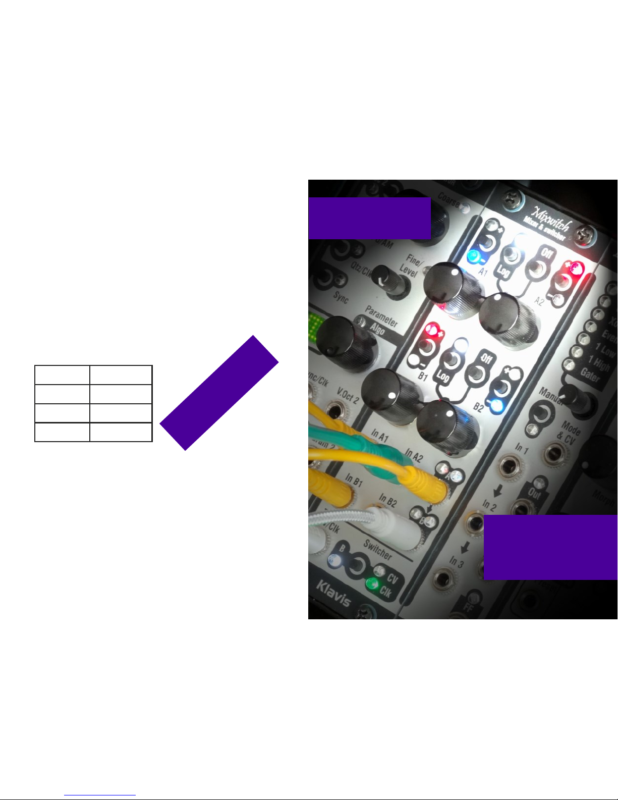
USAGE & PANEL
The Mixwitch combines a pair
of 2>1 mixers that can be
used as a single 4>1 mixer.
A sequential switch can be
activated to select one of four
inputs or only one of the two
inputs of the second mixer.
Input selection is done by a
clock or a voltage.
Muting and polarity are done
by clickless switching.
When set to Log, a mixer sees
its pots curve fit for audio
purposes and its gain reduced
by 6dB to avoid clipping.
All settings are memorized
over power cycle.
The switcher runs at audio
rate. The manual describes
many applications for
waveshaping, sequencing,
sub-octaves generator, granular synthesis, and more.
Mixwitch
Mixer & switcher
A1 A2
Switcher
CV
Clk
B
CV/Clk
B1 B2
In B1 In B2 B
In A1 In A2
A
Klavis
Off
Log
Log
Off
Switcher mode LEDs on Details
CV Clk B
Off Switcher is disabled - Mixers operate normally
CV, 4 channel • Selects one of four inputs or none according
to a voltage. (1 volt steps)
0 to 4V = none, A1, A2, B1, B2
Clock, 4 channel • Clock/trigger calls each input sequentially in a
loop.
Clock, 4 channel,
random
blink Clock/trigger calls four inputs randomly; never
calls the same input twice in a row
CV, 2 channel (B) • • Selects one of 2 inputs of mixer B or none
according to a voltage. (1 volt steps) 0 to 2V = none, B1, B2
Mixer A is unaffected
Clock, 2 channel
(B)
• • Each clock pulse alternates between input B1
and B2
Mixer A is unaffected
 Loading...