

Page 1

Verbindungen mit System
The Power of Partnership
Gustav Klauke GmbH • Auf dem Knapp 46 • D-42855 Remscheid
Telefon ++49 +2191-907-0 • Telefax ++49 +2191-907-141 • www.klauke.textron.com
HE.14138_A © 09/2011 TE-2
D Bedienungsanleitung
GB Instruction Manual
AHP 700-L
Serialnummer
Page 2

HE.14138_A © 09/2011
Bild/pic./fi g. 1
HE.14176
AHP 700-L
Bedienungsanleitung Akkuhydraulische Pumpe/Instruction Manual
I
7
6
4
5
2
3
1
111098
Page 3

HE.14138_A © 09/2011
AHP 700-L
Battery-hydraulic Pump
Nennspannung (Nominal voltage): 18V DC
Betriebsdruck (Operating pressure): 700 bar (max.)
(VTUBW,MBVLF(NC)t"VGEFN,OBQQt%3FNTDIFJE
)&@#
HE.14136
17
2
3
6
5
4
HE.14137
TOTAL
t = 0.34 h
Q = 0.49 Ah
n = 43
HE.14176
AHP 700-L
Bedienungsanleitung Akkuhydraulische Pumpe/Instruction Manual
II
12
4
304711 batch# e.g. 304711
CV datecode e.g. C = 2009; V = July.
142 consecutive# e.g. „142“ = tool # 142
Bild/pic./fi g. 2
datecode
Year Code Month Code Month Code
2007 A Jan. N July V
2008 B Feb. P Aug. W
2009 C Mar. Q Sept. X
2010 D Apr. R Oct. Y
2011 E May S Nov. Z
2012 F June T Dec. 1
5
3
Page 4

HE.14138_A © 09/2011
AHP 700-L
Bedienungsanleitung Akkuhydraulische Pumpe/Instruction Manual
III
Bild/pic./fi g. 3 Bild/pic./fi g. 4
(BL1830)
22 min.
RAL2
CLICK
10 - 40°C
Bild/pic./fi g. 5 Bild/pic./fi g. 6 Bild/pic./fi g. 7
Bild/pic./fi g. 8 Bild/pic./fi g. 9
Bild/pic./fi g. 10
Li-ion
Bild/pic./fi g. 11
®
#884676B996
#884598C990
Bild/pic./fi g. 12
CLICK
Page 5

HE.14138_A © 09/2011
AHP 700-L
Bedienungsanleitung Akkuhydraulische Pumpe/Instruction Manual
IV
Bild/pic./fi g. 16
Bild/pic./fi g. 14Bild/pic./fi g. 13
M
T
= 10 Nm max.
Bild/pic./fi g. 15
1.
2.
1.
2.
2.
1.
2.
3.
Page 6

HE.14138_A © 09/2011
AHP 700-L
Bedienungsanleitung Akkuhydraulische Pumpe/Instruction Manual
V
1 Pressen / Crimping
t
P
max.
= 700 bar
t
r
<t
r
t
r
t
r
>t
r
set reset
Bild/pic./fi g. 17
1
Page 7

HE.14138_A © 09/2011
AHP 700-L
Bedienungsanleitung Akkuhydraulische Pumpe/Instruction Manual
VI
2 Schneiden / Cutting
t
MAN MOTOR
STOPSTOP
Bild/pic./fi g. 18
2
Page 8

HE.14138_A © 09/2011
AHP 700-L
Bedienungsanleitung Akkuhydraulische Pumpe/Instruction Manual
VII
3 Stanzen / Punching
t
Bild/pic./fi g. 19
Page 9

HE.14138_A © 09/2011
AHP 700-L
Bedienungsanleitung Akkuhydraulische Pumpe/Instruction Manual
VIII
3 Biegen / Bending
t
mit Näherungsschalter
with approach switch
t
30°
90°
Bild/pic./fi g. 20
Page 10

HE.14138_A © 09/2011
AHP 700-L
Bedienungsanleitung Akkuhydraulische Pumpe/Instruction Manual
IX
Bild/pic./fi g. 21
Page 11

HE.14138_A © 09/2011
AHP 700-L
Bedienungsanleitung Akkuhydraulische Pumpe/Instruction Manual
X
Tab. 1
Pressen
Crimping
Schneiden
Cutting
Stanzen
Punching
Biegen
Bending
Ablesen
Reading
Programm
1
XX
Programm
2
(X) X X*
Programm
3
XX
Position
7
X
* mit dem Stromschienenbearbeitungszentrum (X) eingeschränkte Funktionalität
with bus bar tool center Limited functionality
1
2
TOTAL
t = 0.34 h
Q = 0.49 Ah
n = 43
Page 12
HE.14138_A © 09/2011
AHP 700-L
Bedienungsanleitung Akkuhydraulische Pumpe/Instruction Manual
XI
Bild/pic./fi g. 22
Abb. ähnlich
pic. similar
Page 13

HE.14138_A © 09/2011
AHP 700-L
Bedienungsanleitung Akkuhydraulische Pumpe/Instruction Manual
XII
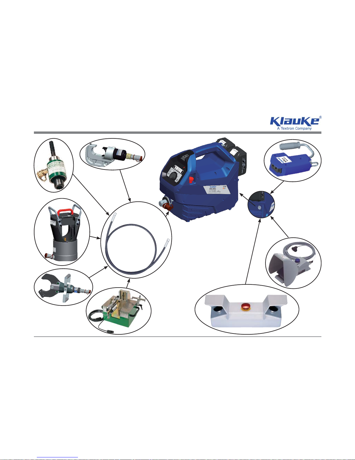
Lieferumfang/Scope of delivery
Bitte prüfen Sie, ob Sie alle im Lieferumfang angeführten Teile erhalten haben:
Please check whether you received all parts mentioned in the scope of supply:
Pos. Anz./Qty. Bezeichnung/Description Art.#
11
Akkuhydraulische Pumpe
Battery hydraulic pump
AHP 700-L
22
Akkus 18 V DC / 3 Ah / Li-Ion
Battery 18 V DC / 3 Ah / Li-Ion
RAL2
31
Schnellladegerät
Quick-charger
LGL1
41
Hochdruckschlauch 2m inkl. Öl
High-pressure hose 2 m w oil
HSOEL2
51
Tragegurt
Shoulder strap
TG3
61
Tasche für Zubehör
Bag for accessories
TT2
71
Bedienungsanleitung
Instrucion manual
HE.14138
81
Handtaster
Hand switch
HTA4
5
3
6
7
4
Abb. ähnlich
pic. similar
1
2
Bild/pic./fi g. 23
8
Page 14

HE.14138_A © 09/2011
AHP 700-L
Bedienungsanleitung Akkuhydraulische Pumpe/Instruction Manual
XIII
1
4
3
2
5
6
Abb. ähnlich
pic. similar
Bild/pic./fi g. 24
7
Abb. ähnlich
pic. similar
Ø 140 mm min.
Zubehör/Accessories
Folgendes Zubehör kann unter u.a. Art.-Nr. bestellt werden:
The following accessories can be ordered:
Pos. Bezeichnung/Description Art.#
1
Netzadapter 18 V für 230 V Netzspannung
Mains adapter 18 V for 230 V voltage
NG2230
2
Sicherheits-Fußtaster incl. Anschlußkabel 4m
Foot switch
FTA4
3
Zweihandsicherheitssteuerung
Two hand safety control system
ZST4
4
USB-Adapter
USB-adapter
PGA1
5
Dig. Anzeigengerät zur Kraft- und Druckmessung
Digital meter for force and pressure measurement
TC1U
6
Drucksensor und Anschlußkabel
Pressure sensor and connecting cable
TP1000T
7
Hochdruckschlauch 3m incl. Öl/oil
High-pressure hoses 3m incl. Öl/oil
HSOEL3
-“- 4m incl. Öl/oil HSOEL4
-“- 5m incl. Öl/oil HSOEL5
-“- 6m incl. Öl/oil HSOEL6
-“- 8m incl. Öl/oil HSOEL8
-“- 10m incl. Öl/oil HSOEL10
Page 15

HE.14138_A © 09/2011
AHP 700-L
Bedienungsanleitung Akkuhydraulische Pumpe/Instruction Manual
XIV
D GB F
Tab. 2
Wann / When / Quand Warum / Why / Pourquoi
20 sec
nach Arbeitsvorgang
after working cycle
après opération de travail
2 x
nach Einsetzen des Akkus
after inserting the battery
après mise en place de
l’accumulateur
Selbsttest
Self check
autocontrôle
20 sec/2Hz
nach Arbeitsvorgang
after working cycle
après opération de travail
20 sec/5Hz
während der Übertemperatur
while exceeding the temp. limit
pendant surchauffe
Werkzeug zu heiß
Unit too hot
outil surchauffé
20 sec
20 sec/2Hz
nach Arbeitsvorgang
after working cycle
après opération de travail
+
1 x
nach Arbeitsvorgang
after working cycle
après opération de travail
Fehler: der notwendige Pressdruck wurde nicht erreicht. Es
handelt sich um eine manuelle Unterbrechung der Pressung bei
stehendem Motor.
Error: the required pressure has not been reached. The operator
has interrupted the pressing cycle manually while the motor was
not running.
ERREUR: Pression necessaire pas atteinte. Il s‘agît d‘une interruption manuelle de la sertissage au moteur arrêté.
3 x 3 x
nach Arbeitsvorgang
after working cycle
après opération de travail
Schwerwiegender Fehler: Pressdruck wurde bei laufendem Motor
nicht erreicht.
Serious Error: The pressure has not been reached while the motor
was running.
ERREUR GRAVE: Pression pas atteinte au moteur courant.
Page 16

HE.14138_A © 09/2011
AHP 700-L
Bedienungsanleitung Akkuhydraulische Pumpe/Instruction Manual
XV
E RUS
Tab. 2
Cuándo /
Когда это происходит
¿por qué? /
Причина
20 sec
Después del proceso de trabajo
после цикла опрессовки
2 x
Después de insertar la batería
при установке аккумулятора
Auto-test
Самодиагностика инструмента
20 sec/2Hz
Después del proceso de trabajo
после цикла опрессовки
20 sec/5Hz
en caso de temperatura excesiva
при высокой температуре внутри корпуса
Herramienta demasiado caliente
Перегрев инструмента
20 sec
20 sec/2Hz
Después del proceso de trabajo
после цикла опрессовки
+
1 x
Después del proceso de trabajo
после цикла опрессовки
Error: No se ha alcanzado la presión necesaria o el operador
ha interrumpido el ciclo a mano mientras el motor ha parado.
Ошибка: не было достигнуто требуемое усилие
опрессовки или оператор прервал процесс опрессовки
вручную, когда двигатель остановился.
3 x 3 x
Después del proceso de trabajo
после цикла опрессовки
Error grave: No se ha alcanzado presión mientras el motor
estaba en marcha
Серьезная ошибка: не было достигнуто требуемое усилие
опрессовки во время работы двигателя
Page 17

HE.14138_A © 09/2011
Bedienungsanleitung Akkuhydraulische Pumpe
1
AHP 700-L
D
original
bed.anl.
Inhaltsangabe
1. Einleitung
2. Garantie
3. Beschreibung der elektro-hydraulischen Pumpe
3.1 Beschreibung der Komponenten
3.2 Kurzbeschreibung der wesentlichen Leistungsmerkmale
3.3 Beschreibung der Werkzeugindikation
3.4 Beschreibung des Preßvorganges
3.5 Beschreibung des Schneidvorganges
3.6 Beschreibung des Loch-/Stanzvorganges
3.7 Beschreibung des Biegevorganges
3.8 Beschreibung des Ablesevorganges
4. Hinweise zum bestimmungsgemäßen Gebrauch
4.1 Bedienung des Gerätes
4.2 Erläuterung des Anwendungsbereiches
4.3 Wartungshinweise Ölwechsel-Intervalle
4.4 Hinweis, welche (Ersatz-) Teile vom Kunden selber ausgewechselt werden dürfen.
5. Verhalten bei Störungen an der Pumpe
6. Technischen Daten
7. Außerbetriebnahme/Entsorgung
Page 18

HE.14138_A © 09/2011
Bedienungsanleitung Akkuhydraulische Pumpe
2
AHP 700-L
D
original
bed.anl.
Symbole
Sicherheitstechnische Hinweise
Bitte unbedingt beachten, um Personen- und Umweltschäden zu vermeiden.
Anwendungstechnische Hinweise
Bitte unbedingt beachten, um Schäden am Werkzeug zu vermeiden.
1. Einleitung
Vor Inbetriebnahme Ihres Werkzeuges lesen Sie sich die Bedienungsanleitung sorgfältig durch.
Benutzen Sie dieses Gerät ausschließlich für den bestimmungsgemäßen Gebrauch unter Berücksichtigung der allgemeinen Sicherheits- und Unfallverhütungsvorschriften.
Pressungen, Stanzungen und sowie Schneid- und Biegevorgänge mithilfe dieses Gerätes dürfen nur durch eine
elektrotechnisch unterwiesene Person durchgeführt werden. Das Mindestalter beträgt 16 Jahre.
Diese Bedienungsanleitung ist während der gesamten Lebensdauer des Werkzeuges mitzuführen.
Der Betreiber muß
• dem Bediener die Betriebsanleitung zugänglich machen und
• sich vergewissern, daß der Bediener sie gelesen und verstanden hat.
2. Garantie
Die Garantie beträgt 24 Monate ab Lieferdatum bei sachgemäßer Bedienung und unter Einhaltung der vorgeschriebenen Serviceintervalle. Ausgeschlossen von der Garantieerklärung sind Verschleißteile, die sich aus dem bestimmungsgemäßen Gebrauch ergeben. Wir behalten uns ferner das Recht vor, das Produkt nachzuarbeiten.
Page 19

HE.14138_A © 09/2011
Bedienungsanleitung Akkuhydraulische Pumpe
3
AHP 700-L
D
original
bed.anl.
3. Beschreibung der elektro-hydraulischen Pumpe
3.1 Beschreibung der Komponenten
Die elektro-hydraulische Pumpe besteht aus folgenden Komponenten:
Tabelle 3
Pos. Bezeichnung Beschreibung
1 Akku (RAL2/BL1830) wiederaufl adbarer 3Ah Li-Ion Akku (RAL2/BL1830)
Optional: Netzgerät NG2230
2 Akkuentriegelung Entriegelungsschieber für den Akku
3 Not-Rücklaufknopf
Zum Zurückstellen der Preß-, Schneid- und Stanzwerkzeuge
in die Ausgangsposition im Fehlerfall
4 Fach für Fernbedienung Ablagefach z.B. für die Fernbedienung und/oder den Tragegurt
5 Kupplungsstecker Kupplungsstecker zum Anschluß an die Kupplungsmuffe des
Hochdruckhydraulikschlauchs
6 Anschlußbuchse für Fernbedienungen für Handtaster, Fußtaster, Zweihandsteuerung
und andere Bedienelemente
7 Verschlußschraube zur Öleinfüllung Einfüllstutzen mit Schauglas für das Hydrauliköl
8 Programmwahlschalter Drehknopf für die Auswahl spezieller Programme zum Pressen,
Schneiden und Stanzen sowie eine Stellung für die Datenausgabe
9 OLED Display hochmodernes organisches Display zum Anzeigen von
Geräte- und Zustandsfunktionen
10 LED Kontrollinstrument zum Feststellen des Ladezustandes,
eines Werkzeugfehlers und zur Wartungsanzeige.
11 Vor- und Rücklauftaster Auslösung/Stoppen des Arbeitsvorgangs
Page 20

HE.14138_A © 09/2011
Bedienungsanleitung Akkuhydraulische Pumpe
4
AHP 700-L
D
original
bed.anl.
3.2 Kurzbeschreibung der wesentlichen Leistungsmerkmale
Die Pumpe ist mit einem Nachlaufstopp ausgerüstet, der den Vorschub nach Loslassen des Bedienungsschalters
sofort stoppt.
Die Pumpe ist mit einer Doppelkolbenpumpe ausgestattet, die durch einen schnellen Vorschub bis zur Berührung
des Werkstücks gekennzeichnet ist.
Die Pumpe ist mit einer Mikroprozessor-Steuerung ausgestattet, die z.B. den Motor nach vollendetem Pressvorgang
abschaltet, Service-Intervalle anzeigt und eine Fehlerdiagnose durchführt.
Alle Funktionen der Pumpe können über den Vor- und Rücklauftaster (Bild 1.11) gesteuert werden. Dadurch bekommen wir eine einfache Handhabung.
Es kann mittels eines USB Adapters (Zubehör) nach Arbeitsende ein Protokoll über die ordungsgemäße Funktion der
Pumpe über den PC ausgedruckt werden.
Durch die Li-Ionen Batterien, die weder Memory Effekt noch Selbstentladung kennen, hat der Bediener auch nach
langen Arbeitspausen immer ein einsatzbereites Gerät. Dazu kommt noch ein geringeres Leistungsgewicht mit 50%
mehr Kapazität und kurzen Ladezeiten im Vergleich zu NiMH Akkus.
Das eingesetzte Öl ist besonders umweltfreundlich und ist mit dem
Blauen Engel ausgezeichnet. Ferner ist das Öl
auch für sehr niedrige Temperaturen geeignet und hat exzellente Schmiereigenschaften, sodaß unsere Geräte quasi
wartungsfrei sind.
Die Pumpe kann in jeder Lage benutzt und transportiert werden, ohne daß Öl austritt.
3.3 Beschreibung der Werkzeugindikation
Die LED (Bild 1.10) dient in Verbindung mit der Steuerungs-Elektronik zur Information über den Zustand des Werkzeuges und des Akkus. Eine Erklärung der einzelnen Anzeigen fi nden Sie in Tabelle 2.
Es sollte vor Arbeitsbeginn der Ladezustand des Akkus (Bild 1.1) überprüft worden sein. Ein niedriger Ladezustand
kann beispielsweise am LCD Display (Bild 1.9) erkannt werden.
Page 21

HE.14138_A © 09/2011
Bedienungsanleitung Akkuhydraulische Pumpe
5
AHP 700-L
D
original
bed.anl.
3.4 Beschreibung des Preßvorganges
Beim Preßvorgang werden die Werkzeugeinsätze gegeneinander gefahren. Der auf das Kabel aufgeschobene Kabelschuh/Verbinder befi ndet sich bei geschlossenem Preßkopf in der feststehenden Hälfte des Preßeinsatzes. Der
auf der Kolbenstange sitzende bewegliche Teil des Preßeinsatzes bewegt sich dabei auf die Preßstelle zu.
Eine Pressung ist abgeschlossen, wenn die Werkzeugeinsätze vollständig zusammengefahren sind.
Weitere Hinweise zur Verpressung von Verbindungsmaterialien entnehmen Sie bitte unserem Montagehinweis im
Katalog.
Die manuelle Rücklaufunterbrechung mit Teach-in ermöglicht die Einprogrammierung der Stoppposition im Rücklauf,
sodaß der Kolben bei der nächsten Verpressung/Schnitt an der gleichen Stelle stoppt, an der auch die vorhergehende Verpressung/Schnitt gestoppt wurde.
3.5 Beschreibung des Schneidvorganges
Bei Schneidvorgängen nach dem Scherenprinzip wird das Kabel in die geöffneten Schneidbacken des Schneidkopfes eingelegt, bzw. der Schneidkopf so an das Kabel angelegt, sodaß sich die Lage des Schneidkopfes während der
gesamten Schneiddauer nicht ändert.
Um ungünstige Scherwirkungen zu vermeiden müssen die Scheren immer lotrecht auf das zu schneidende Kabel
zufahren.
Bei dem Scherenprinzip bewegen sich zwei Messer gleichzeitig auf das zu schneidende Kabel zu.
Bei Scheren nach dem Guillotineprinzip müssen nach Einlegen des Kabels sicher verschlossen werden bevor der
Schneidvorgang durch Auslösung des Bedienungsschalters eingeleitet wird. Das bewegliche Messer bewegt sich
linear auf das zu schneidende Kabel, bzw. das feststehende Messer zu.
3.6 Beschreibung des Loch-/Stanzvorganges
Ein Stanzvorgang wird gekennzeichnet durch das Einziehen des Stempels in die Matrize. Dazu muß der Stempel bis
an das Blech herangeschraubt werden.
Nach Beendigung des Stanzvorganges schaltet die Pumpe ab, um eine Zerstörung von Stempel und Matrize durch
ungewollte Kontaktierung von Stempel und Matrizenboden zu verhindern.
Achtung
Bei dünnen Blechen und bei weichen Werkstoffen (z.B. Kunststoffe) ist die automatische Abschaltung nicht
immer gewährleistet und der Bediener muß das Gerät manuell abschalten.
1
2
Page 22

HE.14138_A © 09/2011
Bedienungsanleitung Akkuhydraulische Pumpe
6
AHP 700-L
D
original
bed.anl.
3.7 Beschreibung des Biegevorganges
Dieser Betriebszustand eignet sich besonders für den Betrieb des Stromschienenbiegegerätes in Verbindung mit
dem Näherungsschalter.
Der Arbeitshub kann in jeder Position unterbrochen werden, ohne dass der Kolben in die Ausgangslage zurückfährt.
Bei nochmaliger Betätigung wird der Arbeitszyklus an dieser Stelle fortgesetzt.
Für weitere Hinweise lesen Sie bitte die Bedienungsanleitung des Stromschienenbiegegerätes.
4. Hinweise zum bestimmungsgemäßen Gebrauch
Die Pumpe kann in jeder Lage transportiert und benutzt werden.
Achtung
In Verbindung mit einem 2 m Hochdruckschlauch ist das Arbeiten im Kabelgraben nicht möglich. Für diese
Anwendung wird mindestens ein 3 m Schlauch benötigt.
4.1 Bedienung des Gerätes
1. Die Kupplungsmuffe des Hydraulikschlauches HSOEL2 (Bild 23.4) wird mit dem an der Pumpe befi ndlichen Kupp-
lungsstecker (Bild 1.5) verbunden (Bild 16).
2. Auswahl des zu verwendeten Preß- oder Schneidkopfes, Loch- bzw. Stanzwerkzeuges oder Stromschienenbiegewerkzeuges nebst Zubehör.
3. Die ausgewählte Arbeitseinheit wird über den Hydraulikschlauch HSOEL2 (Bild 23.4) mit der Pumpe verbunden
(Bild 16).
Achtung
Pumpe nicht ohne Arbeitseinheit betreiben!
Achtung
Vor Inbetriebnahme Ölstand prüfen und ggf. auffüllen (Bilder 13 - 15).
Page 23

HE.14138_A © 09/2011
Bedienungsanleitung Akkuhydraulische Pumpe
7
AHP 700-L
D
original
bed.anl.
4. Neben dem Vor- und Rücklauftaster (Bild 1.11) zur Bedienung der Pumpe können auch folgende Zubehörteile angeschlossen werden:
• Handtaster HTA4 (Bild 23.2)
• Fußtaster inkl. 4m Anschlußkabel FTA4 (Bild 24.3)
• Zweihandsicherheitssteuerung ZST4 (Bild 24.4)
Die Pumpe erkennt die verschiedenen Kontrollgeräte beim Einstecken über eine spezielle Kodierung. Der Vor- und
Rücklauftaster (Bild 1.11) an der Pumpe wird damit inaktiv gesetzt.
5. Der Akku und ggf. der Reserve-Akku werden in die dafür vorgesehenen Halterungen gesteckt (siehe Bild 12).
6. Die Pumpe ist nun betriebsbereit. Das LCD-Display (Bild 1.9) ist aktiviert.
7. Wählen Sie mit Hilfe des Programmwahlschalters (Bild 1.8) das gewünschte Programm oder die Ablesefunktion.
8. Der Arbeitsvorgang wird durch Aktivierung der Vorlauffunktion des Vor- und Rücklauftasters eingeleitet. (s.Bild 17ff.)
Achtung
Der Rücklauf der Pumpe über den Vor- und Rücklauftaster (Bild 1.11) ist immer aktiv und kann zu jeden Zeit-
punkt und in jedem Programm ausgeführt werden.
Achtung
Der Stanz-, Loch-, Preß- bzw. Schneidvorgang kann jederzeit durch Loslassen und Durchtreten des Fußtas-
ters (Bild 24.3), bzw. Loslassen der Zweihandsicherungssteuerung (Bild 24.4) unterbrochen werden.
Ist der Fußtaster (Bild 24.3) einmal ganz durchgetreten worden, so muß er durch Drücken des Entriegelungsknopfes
wieder betriebsbereit gemacht werden.
Achtung
Vor Auswechselung der Werkzeug-/Schneideinsätze unbedingt den Akku aus der Pumpe entfernen
um unbeabsichtigtes Betätigen auszuschliessen.
Zum Transport der Pumpe stellen Sie den Programmwahlschalter (Bild 1.8) auf Stellung 7 um einen unbeabsichtigten Anlauf der Pumpe auszuschließen.
Page 24

HE.14138_A © 09/2011
Bedienungsanleitung Akkuhydraulische Pumpe
8
AHP 700-L
D
original
bed.anl.
4.2 Erläuterung des Anwendungsbereiches
Unsere elektro-hydraulischen Pumpen können mit allen in unserem Katalog befi ndlichen Köpfen betrieben werden.
Achtung
Es dürfen keine unter Spannung stehenden Teile geschnitten, verpreßt, bzw. gelocht werden.
Vor Arbeitsbeginn ist ein spannungsfreier Zustand des Arbeitsumfedes sicherzustellen.
Die Geräte sind nicht für den Dauerbetrieb geeignet. Es muß nach ca. 100 Verpressungen bzw. 80-90 Schnitte
hintereinander eine kurze Pause von mindestens einer viertel Stunde eingelegt werden, damit dem Gerät Zeit zur
Abkühlung gegeben wird.
Achtung
Bei zu intensivem Gebrauch mit entsprechender Erhitzung kann es zu Schäden am Gerät kommen.
Achtung
Beim Betrieb von Elektromotoren können Funken entstehen, die feuergefährliche oder explosive Stoffe in
Brand setzen können.
Achtung
Das elektrohydraulische Aggregat darf nicht bei starkem Regen oder unter Wasser eingesetzt werden.
Das Gerät kann in einem Temperaturbereich von -12°C bis +40°C sowohl im Innen- als auch im Aussenbereich
eingesetzt werden.
Page 25

HE.14138_A © 09/2011
Bedienungsanleitung Akkuhydraulische Pumpe
9
AHP 700-L
D
original
bed.anl.
4.3 Wartungshinweise und Ölwechsel-Intervalle
Das Gerät ist nach jedem Gebrauch zu reinigen und trocken zu lagern. Sowohl Akku als auch Ladegerät müssen vor
Feuchtigkeit und vor Fremdkörpern geschützt werden.
Die Pumpe besitzt eine Verschlußschraube mit Schauglas (Bild 1.7) an dem der Ölstand jederzeit abgelesen werden
kann. Ist der Ölstand zu niederig muß entsprechend ÖL nachgefüllt werden (Bilder 13 - 15).
Folgende Hydrauliköle können bei Umgebungstemperaturen von -12°C bis +40°C verwendet werden:
Hydrauliköle auf Esterbasis: Rivolta S.B.H. 11, Shell Naturell HF-E 15
Mineralöle: Shell Tellus T 15, AVIA HVI 15, Mobil DTE 11, NUTO H 15, Rando HD - Z15, Agip OSO 15, BP Energol
HLP 15.
Es können auch andere vergleichbare Hydrauliköle verwendet werden.
Der Hydraulikschlauch und die Armaturen müssen vor und nach der Anwendung auf Beschädigungen und Undich-
tigkeiten hin überprüft werden.
Achtung
Pfl egen Sie das Werkzeug mit Sorgfalt. Kontrollieren Sie, ob bewegliche Geräteteile einwandfrei funktio-
nieren und nicht klemmen, ob Teile gebrochen oder so beschädigt sind, daß die Funktion des Elektrowerkzeugs beeinträchtigt ist!
Das Gerät ist mit einem Mikroprozessor ausgestattet, der den Anwender durch 20 sekündiges Blinken nach dem
Arbeitsvorgang auf fällige Wartungen hinweist. Ist eine Wartung nach 10.000 Zyklen fällig, muß das Gerät zu einem
autorisierten Service Center (ASC) eingeschickt werden. Bei Nichtbeachtung erlischt der Garantieanspruch. Im Rahmen des bestimmungsgemäßen Gebrauchs dürfen vom Kunden nur der Akku gewechselt werden.
Achtung
Geräteversiegelung nicht beschädigen. Bei Beschädigung der Geräteversiegelung erlischt der Garantieanspruch!
Achtung
Lassen Sie beschädigte Teile vor dem Einsatz des elektrischen Gerätes von qualifi ziertem Fachpersonal
oder durch unser Klauke Service Center (ASC) reparieren!
Page 26

HE.14138_A © 09/2011
Bedienungsanleitung Akkuhydraulische Pumpe
10
AHP 700-L
D
original
bed.anl.
Es ist empfehlenswert, die Pumpe in regelmäßigen Abständen durch einen Sachkundigen zu warten, um einen einwandfreien Zustand vor dem nächsten Gebrauch zu gewährleisten.
Tabelle 2 - Wartungsplan:
Was? Wann? Wer?
Reinigen nach jedem Gebrauch Bediener
Ölstand prüfen wöchentlich Bediener
Hochdruckschlauch prüfen wöchentlich Sachkundigen
Ordungsgemäßer Zustand ¼-jährlich Elektrofachkraft
Hydrauliköl wechseln jährlich Werk/Sachkundigen
Das Hydrauliköl ist nach spätestens einem Jahr oder bei häufi gem Gebrauch nach ca. 10.000 Zyklen, bzw. 8000
Schnittvorgängen, komplett auszutauschen. Wir empfehlen, diesen Ölwechsel im Werk ausführen zu lassen.
Achtung
Bitte verwenden Sie nur sauberes, einwandfreies Hydrauliköl.
Achtung
Hydrauliköle können Hautausschläge und andere Gesundheitsschädigungen hervorrufen. Vermeiden Sie
längeren Hautkontakt. Waschen Sie sich nach jedem Kontakt gründlich.
Achtung
Verschüttetes Hydrauliköl muß sofort mit Saugmaterial gebunden werden.
4.4 Hinweis, welche (Ersatz-) Teile vom Kunden selber ausgewechselt werden dürfen.
Innerhalb des Gewährleistungszeitraums darf vom Kunden nur das Öl gewechselt werden.
Achtung
Versiegelung nicht beschädigen!
Führen Sie keine eigenen Reparaturen durch und entfernen Sie keine Bauteile wie Schrauben oder andere Komponenten.
Page 27

HE.14138_A © 09/2011
Bedienungsanleitung Akkuhydraulische Pumpe
11
AHP 700-L
D
original
bed.anl.
5. Verhalten bei Störungen an der Pumpe
a.) Regelmäßiges Blinken/Leuchten der roten Leuchtdiode (Bild 1.10) oder Ertönen eines akustischen Warnsignals.
siehe Tabelle 2. Sollte sich die Störung nicht abstellen lassen, ist das Werkzeug an das nächst gelegene Service
Center (ASC) zu schicken.
b.) An der Pumpe oder am Preß-/Schneid- bzw. Stanzkopf tritt Hydrauliköl aus.
Das jeweilige Bauteil oder ggf. das gesamte Aggregat muß zur Reparatur ins Werk eingeschickt werden. Nicht öff-
nen und die Geräteversiegelung nicht entfernen.
c.) Die rote LED (Bild 1.10) blinkt 3x und gleichzeitig ertönen 3 Warnsignale (siehe Tab. 2).
Schwerer Fehler! Wenn dieser Fehler wiederholt auftritt ist das Werkzeug einzuschicken. Nicht öffnen und die Gerä-
teversiegelung nicht entfernen. Bei einmaligem Auftreten dieses Fehlers muß der betroffene Kabelschuh/Verbinder
nachgepresst werden.
6. Technischen Daten
Schutzart: IP 43
Betriebsdruck: 700 bar
Hydrauliköl: Rivolta S.B.H. 11
Eingefüllte Ölmenge ca. 760 ml
Nutzbare Ölmenge ca. 740 ml
zulässige Umgebungstemperatur: -12°C bis +40°C
Steuerspannung: 18 V DC
Antriebsmotor: Gleichstrom-Permanentfeldmotor
Gewicht der Pumpe: ca. 4,9 kg
Akkuspannung: 18 V
Akkukapazität: 3 Ah (RAL2/BL1830)
Akku-Ladezeit: 22 min. (RAL2/BL1830)
Schalldruckpegel: < 70 dB (A) in 1m Abstand
Vibrationen: < 2,5 m/s² (gewichteter Effektivwert der Beschleunigung)
Page 28
HE.14138_A © 09/2011
Bedienungsanleitung Akkuhydraulische Pumpe
12
AHP 700-L
D
original
bed.anl.
7. Außerbetriebnahme/Entsorgung
Dieses Gerät fällt in den Geltungsbereich der Europäischen WEEE (2002/96/EG) und RoHS Richtlinien (2002/95/
EG), die in Deutschland durch das Elektro- und Elektronikgerätegesetz (ElektroG) umgesetzt wurden.
Informationen dazu fi nden Sie auf unserer Homepage www.klauke.com unter WEEE & RoHS.
Akkus müssen unter Berücksichtigung der Batterieverordung speziell (getrennt) entsorgt werden.
Achtung
Das Gerät darf nicht im Restmüll entsorgt werden. Die Entsorgung muss durch den Entsorgungspartner der
Fa. Klauke vornehmen werden.
Kontaktadresse:
WEEE-Abholung@Klauke.Textron.com
Anmerkung
Diese Bedienungsanleitung kann jederzeit kostenlos unter der Bestell-Nr. HE.14138 nachbestellt werden.
Page 29

HE.14138_A © 09/2011 1
AHP 700-L
GB
Instruction Manual Battery-hydraulic Pump
authorised
copy
Index
1. Introduction
2. Warranty
3. Description of the electro-hydraulic pumping unit
3.1 Description of components
3.2 Brief description of the important features of the unit
3.3 Description of the tool indication
3.4 Description of crimping cycles
3.5 Description of cutting cycles
3.6 Description of punching cycles
3.7 Description of bending cycles
3.8 Description of reading procedure
4. Remarks in respect of the determined use
4.1 Operation of the unit
4.2 Explanation of the application range
4.3 Oil changing and maintenance cycles
4.4 Reference, as to which (spare-) parts can be exchanged by the customer
5. Troubleshooting
6. Technical data
7. Putting out of service/waste disposal
Page 30

HE.14138_A © 09/2011 2
AHP 700-L
GB
Instruction Manual Battery-hydraulic Pump
authorised
copy
Symbols
Safety Warnings
Please do not disregard to avoid injuries and environmental damage
Application Warnings
Please do not disregard to avoid damaging the tool.
1. Introduction
Before starting to use the tool please read the instruction manual carefully.
Use this tool exclusively for its determined use and follow all applicable safety instructions.
Mounting and assembly of connecting material with the help of this tool must only be performed by specially trained
personnel. The minimum age is 16 years.
This instruction manual has to be carried along during the entire life span of that tool.
The operator has
• to guarantee the availability of the instruction manual for the user and
• to make sure, that the user has read and understood the instruction manual.
2. Warranty
If the tool is operated according to its intended use and the regular maintenance services are observed our warranty is 24 months from the time of delivery. Worn-out parts resulting from its intended use are excluded. We
reserve the right to rework the tool in case of a justifi ed warranty claim.
Page 31
HE.14138_A © 09/2011 3
AHP 700-L
GB
Instruction Manual Battery-hydraulic Pump
authorised
copy
3. Description of the electro-hydraulic pumping unit
3.1 Description of the components
The electro-hydraulic pumping unit consists of the following components:
Table 3 (see pic.1)
Pos. Description Function
1 Battery (RAL2/BL1830) rechargeable 3Ah Li-Ion battery (RAL2/BL1830)
Optional: mains adapter NG2230
2
battery lock Slide to unlock the battery
3 Emergency stop button To reset the crimping, cutting and punching tools into the starting
position in case of an error.
4 Compartment ~ e.g. for remote control and/or carrying belt
5 Male plug Male plug to connect to a female plug on the hose
6 Socket for remote control, safety foot switch, two hand control and other
controls
7 Oil plug Oil plug with inspection glass for the hydraulic oil
8 Program selection switch Turning knob for the selection of special programs for crimping,
cutting, punching as well as a position to read out data.
9 OLED Display High tech organic display to indicate tool and crimping/cutting data
10
LED (red) Indicator for Battery charge, Service Intervals and faults
11 Forward and return keys To start/stop the working cycle
Page 32

HE.14138_A © 09/2011 4
AHP 700-L
GB
Instruction Manual Battery-hydraulic Pump
authorised
copy
3.2 Brief description of the important features of the unit
The unit is equipped with a special brake which stops the forward motion of the piston/dies when the trigger is released.
Through an optional USB adapter a report can be generated at the end of a working session at a PC documenting
the proper function of the unit.
The unit is equipped with a double piston pump which is characterised by a rapid approach of the dies towards the
connector and a slow crimping motion.
All tool functions can be controlled by one rocker trigger (pic. 1.11). This results in an easy handling.
The tool is equipped with a microprocessor which indicates service intervals and low battery charges and performs
internal checks sending out acoustical and optical warning signals in case of a detected fault.
Li-Ion batteries do neither have a memory effect nor self discharge. Even after long periods of non operation the tool
is always ready to operate. In addition we see a lower power weight ratio with 50% more capacity and shorter charging cycles compared to NiMH batteries.
The oil used in our tool is particularly environmentally friendly and and has been rewarded „The Blue Angel“. The oil
is also suitable for low temperatures and has excellent lubrication characteristics.
The pump can be operated and transported in all positions without any oil leakages.
3.3 Description of the tool indication
This tool is equipped with a special circuit board incorporating several important features to inform the user about the
current status of the unit. Please see Table 2 for more details.
Prior to operating the unit the charging level of the battery (pic. 1.1) should have been tested. A low charging level
can be detected by the LCD display (pic. 1.9).
3.4 Description of crimping cycles
During a crimping cycle the dies approach and fi nally contact each other. The connector mounted on a cable must
be located in the stationary half of the die whereas the moving die is approaching the compression point. The crimp
is complete when the dies contact each other and when the max. operating pressure is reached. For additional instructions please reference the assembly instructions in the Klauke catalogue.
1
Page 33

HE.14138_A © 09/2011 5
AHP 700-L
GB
Instruction Manual Battery-hydraulic Pump
authorised
copy
A manual retraction stop with Teach-in allows the user to programm the stop position during the retraction of the piston so that the piston stops at the very position where the previous crimping/cutting cycle had been stopped.
3.5 Description of cutting cycles
When cutting, the cables/conductors must be positioned into the cutting head in a way that the position of the cutter
does not change during the cutting cycle. To avoid shearing forces during the cut the blades have to approach the
cable/conductor vertically in a 90° angle.
During the cut the blades approach the cable simultaneously.
Guillotine type cutters must be closed safely after inserting the cable before the cutting cycle is initiated by actuating
the trigger. The moveable blade approaches the cable, resp. the stationary blade in a linear movement.
3.6 Description of punching cycles
A punching cycle is characterized by drawing the die into the matrice. The die has to contact the sheet metal prior to
starting the punching cycle.
After terminating the punching cycle the pump switches off automatically to avoid damaging punch and matrice by
unintened contact.
Attention
With thin sheet metals and soft materials (e.g. plastics) the automatic switch off can not be garanteed and
the user has to stop the process manually.
3.7 Description of bending cycles
This operation mode is particularly applicable for the operation with the bus bar bending tool in combination with the
approach switch.
The working cycle can be interrupted in any position without retracting the piston into the starting position. When
actuating the trigger again the working cycle will be continued.
For further instructions please read the instruction manual of the bus bar bending tool.
2
Page 34

HE.14138_A © 09/2011 6
AHP 700-L
GB
Instruction Manual Battery-hydraulic Pump
authorised
copy
4. Remarks in respect of the determined use
The pump can be transported and operated in any position.
Attention
In combination with a 2 m high-pressure hose it is not possible to work in a cable trench. For this application
at least a 3 m high-pressure hose is needed.
4.1 Operation of the unit
1. The female coupling of the hydraulic hose HSOEL2 (pic. 23.4) must be connected to the male coupling (pic. 1.5) of
the pump (pic. 1.6).
2. Select the right working unit for the intended application.
3. The selected working unit will be connected via the hydraulic hose HSOEL2 (pic. 23.4) with the pump (pic. 16)
Attention
Do not operate the pump without a working unit.
Attention
Before starting to operate the pump the oil level must be checked and possibly adjusted. (pic. 13 - 15)
.
4. Besides the built-in trigger (pic. 1.11) the following accessories can be connected:
• Remote control HTA4 (pic. 23.2)
• Safety foot switch incl. 4m cable FTA4 (pic. 24.3)
• Two hand safety control ZST4 (pic. 24.4)
The pump recognises the various accessories through a special coding; the built-in trigger (pic. 1.11) will be deactivated accordingly.
5. The battery and possibly the spare battery will be plugged into the sockets (see pic. 12).
6. The pump is now ready to operate. The LCD display (pic. 1.9) is activated.
7. Select the program for the intended application by turning the selection knob (pic. 1.8) or the data function.
8. The working cycle (s. pic. 17ff.) is initiated by activating the advance function of the ‚forward and return keys‘
(pic. 1.11)
Attention
The retraction button of the forward and return keys (pic 1.1 1) is always activ and can be actuated at any time
and any program.
Page 35

HE.14138_A © 09/2011 7
AHP 700-L
GB
Instruction Manual Battery-hydraulic Pump
authorised
copy
Attention
The punching, hole making, crimping and cutting cycle can be stopped at any time by releasing or step-
ping down the actuator of the safety foot switch (pic. 24.3), resp. releasing the the two hand safety switch
(pic. 24.4).
Once the three step safety foot switch has been stepped down, it can only be reactivated by pushing the reset button
of the foot switch. This reset button is located on the top of the foot switch.
Attention
After having terminated the working cycle and prior to changing the dies remove battery to avoid unintended use. Avoid unintended starts. Make sure the switch is in the off position before plugging in.
For transport turn the program selection switch (pic. 1.8) to position 7 to avoid unintended starts.
4.2 Explanation of the application range
The battery hydraulic pump can be operated with all of the cutting-/crimping- and punching heads in our catalogue.
Attention
Do not crimp/cut or punch on live cables or conductors.
Before starting to work make sure there are no live lines in the working area.
The tool is not designed for continued operations. After a sequence of approximately 100 completed cycles you have
to make a break of 15 min. to give the tool time to cool down.
Attention
Too intensive use can cause heat damages for the tool
Attention
During the operation of electric engines sparks can occur which might ignite highly infl ammable or explosi-
ve liquids and materials
Attention
Electric-hydraulic tools should not be operated in pouring rain or under water.
The tool can be operated in a temperature range of -12°C bis +40°C inside as well as outside.
Page 36

HE.14138_A © 09/2011 8
AHP 700-L
GB
Instruction Manual Battery-hydraulic Pump
authorised
copy
4.3 Oil changing and maintenance cycles
For every day service the tool has to be cleaned and dried after each use. The battery cartridge and the charging unit
have to be protected against humidity and dust.
The pump has an oil plug with inspection glass (pic. 1.7) which can be used to determine the proper oil level. If the
oil level should be too low the reservoir must be refi lled (pic. 13 - 15).
The following hydraulic oils are suitable for a temperature range -12°C to +40°C:
Hydraulic oils based on Ester: Rivolta S.B.H. 11, Shell Naturell HF-E 15
Mineral oils: Shell Tellus T 15, AVIA HVI 15, Mobil DTE 11, NUTO H 15, Rando HD - Z15, Agip OSO 15, BP Energol
HLP 15.
Other equivalent hydraulic oils can also be used.
The hydraulic hose and the armature must be checked for damage and leakage.
Attention
Maintain power tools thoroughly. Check for functionality or jamming of moving parts, breakage of parts and
any other condition that may affect the power tools operation.
The battery-hydraulic pump is equipped with a controller enabling the user to see when the next service is due by
fl ashing for 20 sec. at the end of a working cycle. When the next service is due after 10.000 cycles the unit must
be returned to an authorised service center (ASC). Failure to observe this request results in loosing the Warranty.
Preventive maintenance serves your safety. Within the determined use of the tool only the batteries are permitted to
be changed by the customers.
Attention
Do not damage the seals of the tool
Attention
Have the power tool repaired by a qualifi ed expert or by a Klauke ASC before use.
Page 37

HE.14138_A © 09/2011 9
AHP 700-L
GB
Instruction Manual Battery-hydraulic Pump
authorised
copy
It is advisable to have the pump serviced by a specialist during regular intervals to safeguard a technically proper
state before use.
Table 2 - Service schedule
What? When? Who?
Cleaning after each use Service personnel
Check oil level weekly Service personnel
Check high pressure hose weekly Specialist
Proper state quarterly Electric specialist
Change hydraulic oil annually Manufacturer/Specialist
The hydraulic oil has to be completely changed annually or after 10.000 working cycles.
We recommend to have the service done in specialised companies where the save disposal of the oil is guaranteed
for environmental protection.
Attention
Please use only clean, proper hydraulic oil. (Rivolta S.B.H. 11 and other hydraulic oils of similar quality)
Attention
Hydraulic oils can cause cutaneous eruption (eczema) or other health hazards. Avoid longer skin contact.
Wash your hands carefully after each contact.
Attention
Spilled hydraulic oil has to be absorbed immediately.
4.4 Reference as to which spare parts can be exchanged by the customers
Within the determined use of the tool the customers may only change the oil.
Attention
Do not damage the seals of the pump.
Do not attempt to repair the tool yourself, and do not remove any parts such as screws and other components.
Page 38

HE.14138_A © 09/2011 10
AHP 700-L
GB
Instruction Manual Battery-hydraulic Pump
authorised
copy
5. Troubleshooting
a.) Constant fl ashing/indicating of the red LED (pic 1.10) or the occurence of an acustical warning signal.
see tab. 2. If the failure can not be resolved through the action recommended in tab. 2 return the unit to the
nearest service center (ASC).
b.) The tool or the crimping-/cutting- or punching-head loses oil.
Return the unit or the accessories to the manufacturer. Do not open it and damage the seal of the tool.
c.) The red LED fl ashes 3x and simultaneously 3 acoustic warning signals occure (see tab. 2).
Serious fault! If this fault occures repeatedly return the unit to an Autorized Service Center (ASC). Do not open
it and damage the seal of the tool.
In case of a one time occurence the connector has to be pressed a second time.
6. Technical Data
Protective system: IP 43
max. operation pressure: 700 bar
Hydraulic oil: Rivolta S.B.H. 11
Reservoir capacity: approx. 760 ml
Useable oil capacity: approx. 740 ml
Environmental temperature: -12°C bis +40°C
Control voltage: 18 V DC
Driving motor: direct-current permanent fi eld
Weight of the unit: approx. 4,9 kg
Battery voltage: 18 V
Battery capacity: 3 Ah (RAL2/BL1830)
Charging time: 22 min. (RAL2/BL1830)
Sound level: < 70 dB (A) in 1m distance
Vibrations: < 2,5 m/s²
Page 39

HE.14138_A © 09/2011 11
AHP 700-L
GB
Instruction Manual Battery-hydraulic Pump
authorised
copy
7. Putting out of action/waste disposal
This unit is subjected to the scope of the European WEEE (2002/96/EG) and RoHS (2002/95/EEC) directives. Information about this can be found in our home page www.Klauke.com under ‘WEEE & RoHS’. Battery cartridges must
be specially disposed of according to the EEC Battery Guideline.
Attention
Do not dispose of the unit in your residential waste. Klauke has no legal obligation to take care of their WEEE
outside Germany unless the product has been shipped and invoiced from inside your country by Klauke.
Please contact your distributer to fi nd out more how to get your tool recycled environmental friendly.
Adress:
WEEE-Abholung@Klauke.Textron.com
Remark
Additional instruction manuals are available free of charge. The part # is HE.14138.
Page 40

(D) CE`11 - Konformitätserklärung.
Wir erklären in alleiniger Verantwortlichkeit, daß dieses Produkt mit den
folgenden Normen oder normativen Dokumenten übereinstimmt:
DIN EN 12100 Teil 1 und 2, EN 60204-1, EN 55014-1, EN 55014-2,
EN 60529, EN 982, EN 1037, EN 61000-3-2, EN 61000-3-3 gemäß den
Bestimmungen der Richtlinien 2006/95/EG, 2004/108/EG
(GB) CE`11 - Declaration of conformity.
We declare under our sole responsibility that this product is in conformity
with the following standards or normative documents:
DIN EN 12100 Teil 1 und 2, EN 60204-1, EN 55014-1, EN 55014-2,
EN 60529, EN 982, EN 1037, EN 61000-3-2, EN 61000-3-3 in accordance
with the regulations of directives 2006/95/EEC, 2004/108/EEC
(F) CE`11 - Déclaration de conformité.
Nous déclarons sous notre seule reponsabilité que ce produit est en con-
formité avec les normes ou documents normatifs suivants:
DIN EN 12100 Teil 1 und 2, EN 60204-1, EN 55014-1, EN 55014-2,
EN 60529, EN 982, EN 1037, EN 61000-3-2, EN 61000-3-3 conformément
aux réglementations des directives 2006/95/CEE, 2004/108/CEE
(NL) CE`11 - Konformiteitsverklaring.
Wij verklaren en wij stellen ons er alleen voor verantwoordelijk dat dit
produkt voldoet aan de volgende normen of normatieve documenten:
DIN EN 12100 Teil 1 und 2, EN 60204-1, EN 55014-1, EN 55014-2,
EN 60529, EN 982, EN 1037, EN 61000-3-2, EN 61000-3-3 overeenkomstig de bepalingen van de richtlijnen 2006/95/EEG, 2004/108/EEG.
(I) CE`11 - Dichiarazione di conformità.
Dichiariamo sotto la nostra esclusiva responsabilità che questo prodotto è
conforme alle seguenti norme e documenti normativi:
DIN EN 12100 Teil 1 und 2, EN 60204-1, EN 55014-1, EN 55014-2,
EN 60529, EN 982, EN 1037, EN 61000-3-2, EN 61000-3-3 conformemente alle disposizioni delle direttive 2006/95/CEE, 2004/108/CEE.
(E) CE`11 - Declaración de conformidad.
Declaramos bajo nuestra sola responsabilidad que este producto està en
conformidad con las normas o documentos normativos siguientes:
DIN EN 12100 Teil 1 und 2, EN 60204-1, EN 55014-1, EN 55014-2,
EN 60529, EN 982, EN 1037, EN 61000-3-2, EN 61000-3-3 de acuerdo
con las regulaciones de las directivas 2006/95/CEE, 2004/108/CEE.
(P) CE`11 - Declaração de conformidade.
Declaramos sob nossa exclusiva responsabilidade que este producto
cumpre as seguintes normas ou documentos normativos:
DIN EN 12100 Teil 1 und 2, EN 60204-1, EN 55014-1, EN 55014-2,
EN 60529, EN 982, EN 1037, EN 61000-3-2, EN 61000-3-3 conforme as
disposiçoes das directivas 2006/95/CEE, 2004/108/CEE.
(S) CE`11 - Konformitetsdeklaration.
Vi förklarar pá eget ansvar att denna produkt õverenstämmer med följande
normer eller normativa dokument:
DIN EN 12100 Teil 1 und 2, EN 60204-1, EN 55014-1, EN 55014-2,
EN 60529, EN 982, EN 1037, EN 61000-3-2, EN 61000-3-3 enligt bestãmmelserna i direktiverna 2006/95/EG, 2004/108/EG.
(FIN) CE`11 - Todistus slandardinmukaisuudesta.
Asiasta vastaavana todistamme täten, että tämä tuote on seuraavien
standardien ja standardoimisasiakirjojen vaatimusten mukainen:
DIN EN 12100 Teil 1 und 2, EN 60204-1, EN 55014-1, EN 55014-2,
EN 60529, EN 982, EN 1037, EN 61000-3-2, EN 61000-3-3 ja vastaa
säädoksiä 2006/95/EU, 2004/108/EU.
(N) CE`11 - Konformitetserklæring.
Vi erklærer på eget ansvarlighet at dette produkt er i overensstemmelse
med følgende standarder eller standard-dokumenter:
DIN EN 12100 Teil 1 und 2, EN 60204-1, EN 55014-1, EN 55014-2,
EN 60529, EN 982, EN 1037, EN 61000-3-2, EN 61000-3-3 i henhold til
bestemmelsene i direktive ne 2006/95/EØF, 2004/108/EØF.
Gustav Klauke GmbH • Auf dem Knapp 46 • D-42855 Remscheid
Telefon ++49 +2191-907-0 • Telefax ++49 +2191-907-141 • www.klauke.textron.com
Handgeführtes batteriebetriebenes
Elektrowerkzeug Typ AHP 700-L
Page 41

(DK) CE`11 - Konformitetserklæring.
Vi erklærer under almindeligt ansvardt at dette produkt er i overensstem-
melse med folgende normer eller normative dokumenter:
DIN EN 12100 Teil 1 und 2, EN 60204-1, EN 55014-1, EN 55014-2,
EN 60529, EN 982, EN 1037, EN 61000-3-2, EN 61000-3-3 i henhold til
bestemmelseme i direktiverne 2006/95/EØF, 2004/108/EØF.
(PL) CE`11 - Zgodnosc z dyrektywami CE.
Swiadomi odpowiedzialnosci oswiadczamy, ze niniejszy produkt jest zgod-
ny z nastepujacymi normami lub dokumentacja normatywna:
DIN EN 12100 Teil 1 und 2, EN 60204-1, EN 55014-1, EN 55014-2,
EN 60529, EN 982, EN 1037, EN 61000-3-2, EN 61000-3-3 zgodnie z
postanowieniami wytycznych 2006/95/EG, 2004/108/EG
(GR) CE`11 -ΔΗΛΩΣΗ ΣΥΜΜΟΡΦΩΣΗΣ
Μ αναληψη συνολικης δηλωνομ⋅ οτι το πορον προιον συμϕωνι μ
τα παρακατω ποοτυπα και μ τα ηροτυηα ηου αναϕρονται στα σχπκο
γγραϕα:
DIN EN 12100 Teil 1 und 2, EN 60204-1, EN 55014-1, EN 55014-2,
EN 60529, EN 982, EN 1037, EN 61000-3-2, EN 61000-3-3 συμϕωνα μ
τοχς κονονισμους 2006/95/EEC, 2004/108/EEC.
(H) CE `11 – Megfelelőségi nyilatkozat.
Kéziműködtetésű elektromos kéziszerszámok. Teljes felelősségel kijelent-
jük, hogy ezek a termékek a következő szabványokkal és irányelvekkel
összhangban vannak:
DIN EN 12100 Teil 1 und 2, EN 60204-1, EN 55014-1, EN 55014-2,
EN 60529, EN 982, EN 1037, EN 61000-3-2, EN 61000-3-3 és megfelelnek a rendeltetés szerinti 2006/95/EEC, 2004/108/EEC irányelveknek.
(CZ) CE `11 – Prohlášeni o shode.
Prohlašujeme na vlastni zodpovednost, ze tyto produkty splnuji následujici
normy nebo normativni listiny:
DIN EN 12100 Teil 1 und 2, EN 60204-1, EN 55014-1, EN 55014-2,
EN 60529, EN 982, EN 1037, EN 61000-3-2, EN 61000-3-3 Ve shode se
smernicemi 2006/95/EEC, 2004/108/EEC.
(RO) CE `11 - Declaraţie de conformitate.
Noi declarăm pe propria răspundere că acest produs este în conformitate
cu următoarele norme şi documente normative:
DIN EN 12100 Teil 1 und 2, EN 60204-1, EN 55014-1, EN 55014-2,
EN 60529, EN 982, EN 1037, EN 61000-3-2, EN 61000-3-3 potrivit
dispoziţiilor directivelor 2006/95/EEC, 2004/108/EEC.
Remscheid, den 01.08.2011
___________________________________________
Dipl.-Ing. Joh.-Christoph Schütz, CE-Beauftragter
Gustav Klauke GmbH • Auf dem Knapp 46 • D-42855 Remscheid
Telefon ++49 +2191-907-0 • Telefax ++49 +2191-907-141 • www.klauke.textron.com
Handgeführtes batteriebetriebenes
Elektrowerkzeug Typ AHP 700-L
 Loading...