

Page 1
10030272
10030273
10030274
10030275
10030276
10030300
10031905
10031906
10031910
Dunstabzugshaube
Page 2

2
Inhalt
Sehr geehrter Kunde,
wir gratulieren Ihnen zum Erwerb Ihres Klarstein Gerätes. Lesen Sie die folgenden Anschluss- und Anwendungshinweise sorgfältig durch und befolgen Sie diese, um möglichen technischen Schäden vorzubeugen.
Für Schäden, die durch Missachtung der Sicherheitshinweise und unsachgemäßen Gebrauch entstehen,
übernehmen wir keine Haftung.
Sicherheitshinweise . . . . . . . . . . . . . . . . . . . . . . . . . . . . . 3
Montage . . . . . . . . . . . . . . . . . . . . . . . . . . . . . . . . . . 4
Bedienung . . . . . . . . . . . . . . . . . . . . . . . . . . . . . . . . 10
Reinigung und Wartung . . . . . . . . . . . . . . . . . . . . . . . . . . 13
Fehlerbehebung . . . . . . . . . . . . . . . . . . . . . . . . . . . . . . 14
Hinweise zur Entsorgung . . . . . . . . . . . . . . . . . . . . . . . . . . 15
Konformitätserklärung . . . . . . . . . . . . . . . . . . . . . . . . . . . 15
Page 3

3
Sicherheitshinweise
• Diese Bedienungsanleitung dient zu Ihrer Sicherheit. Lesen Sie Anleitung sorgfältig und bewahren Sie
diese Anleitung stets gut auf, damit Sie jederzeit darauf zurückgreifen können.
Kinder im Haushalt
• Kleine Kinder müssen vom Gerät fern gehalten werden. Sie müssen beaufsichtigt werden, so dass sie
die heißen Teile nicht berühren.
• Dieses Gerät darf von Kindern ab 8 Jahren und Personen mit eingeschränkten körperlichen, sensorischen
und geistigen Fähigkeiten und Kenntnissen verwendet werden, wenn sie in die sichere Verwendung des
Gerätes eingewiesen wurden und die damit verbundenen Gefahren verstehen.
• Halten Sie das Gerät und das Netzkabel außerhalb der Reichweite von Kindern, die jünger als 8 Jahre
sind.
Allgemein
• Das Gerät ist nur für den Hausgebrauch bestimmt.
• Die zugänglichen Teile können während des Betriebs heiß werden.
• Flambieren Sie unter der Dunstabzugshaube nicht.
• Überprüfen Sie den Netzstecker und das Netzkabel regelmäßig. Falls das Netzkabel beschädigt ist, muss
es vom Hersteller bzw. dem Kundendienst ersetzt werden, um Gefahren abzuwenden.
• Lassen Sie das Netzkabel nicht mit heißen Teilen des Gerätes in Berührung kommen.
• Achten Sie darauf, dass das Netzkabel sich nicht unter oder im Gerät verfängt, um Schäden am
Netzkabel zu vermeiden.
• Montieren Sie das Gerät nicht im Freien, an einem feuchten Ort oder in einem Bereich, der von
Wasserlecks betroffen sein kann, z. B. unter oder neben einer Spüle. Lassen Sie das Gerät im Falle eines
Wasserschadens vollständig trocknen.
Reinigung
• Verwenden Sie in der Nähe des Gerätes keine entflammbaren Sprays.
• Entsorgen Sie das Verpackungsmaterial sorgfältig.
• Geben Sie bei der Verwendung und Reinigung des Gerätes Acht. Lesen Sie das Kapitel zu „Reinigung
und Pflege“.
• Zur Reinigung darf kein Dampfreiniger verwendet werden.
Montage
• Die Montage darf nur durch einen qualifizierten Elektriker oder eine anderweitig qualifizierte Person
erfolgen. Die Montage muss korrekt unter der Befolgung der Herstelleranleitung erfolgen.
• Das Gerät ist nicht dazu bestimmt, mit einer externen Zeitschaltuhr oder einer separaten Fernbedienung
gesteuert zu werden.
• In der festen Verdrahtung muss die Möglichkeit einer Schaltkreisunterbrechung gemäß den
Verdrahtungsrichtlinien gegeben sein.
• Informieren Sie sich über die örtlichen Bestimmungen zu Rauchabzügen. Schließen Sie die
Dunstabzugshaube nicht an einen Kaminschacht oder einen Heißluftkanal an. Überzeugen Sie sich,
dass die Raumbelüftung mit den örtlichen Bestimmungen konform ist. Gewährleisten Sie, dass das
Page 4
4
Montage
Volumen des Anzapfstroms des Gerätes nicht 4 Pa (0,04 mbar) übersteigt. Der Raum muss angemessen
belüftet sein, wenn die Dunstabzugshaube gleichzeitig mit Geräten betrieben wird, die Gas oder andere
Brennstoffe verbrennen. Die Luft darf nicht in eine Abzugsleitung abgeführt werden, die als Rauchabzug
für Geräte verwendet wird, die Gas oder andere Brennstoffe verbrennen. Gesetzliche Regelungen
bezüglich Abzügen müssen befolgt werden.
• Schalten Sie vor dem Anschluss des Gerätes die Stromversorung aus. Überprüfen Sie, ob die
Versorgungsspannung mit der Nennspannung auf dem Typenschild Ihres Gerätes übereinstimmt
• Während einer elektrostatischen Entladung (z. B. einem Gewitter) kann das Gerät den Betrieb einstellen.
Dies stellt keine Gefahr oder einen Schaden dar. Trennen Sie die Stromversorgung zum Gerät ab und
verbinden Sie es nach einer Minute wieder.
• Benutzen Sie das Gerät nicht, wenn es Anzeichen von Beschädigungen oder Fehlern gibt. Setzen Sie
sich in dem Fall mit dem Kundendienst in Verbindung.
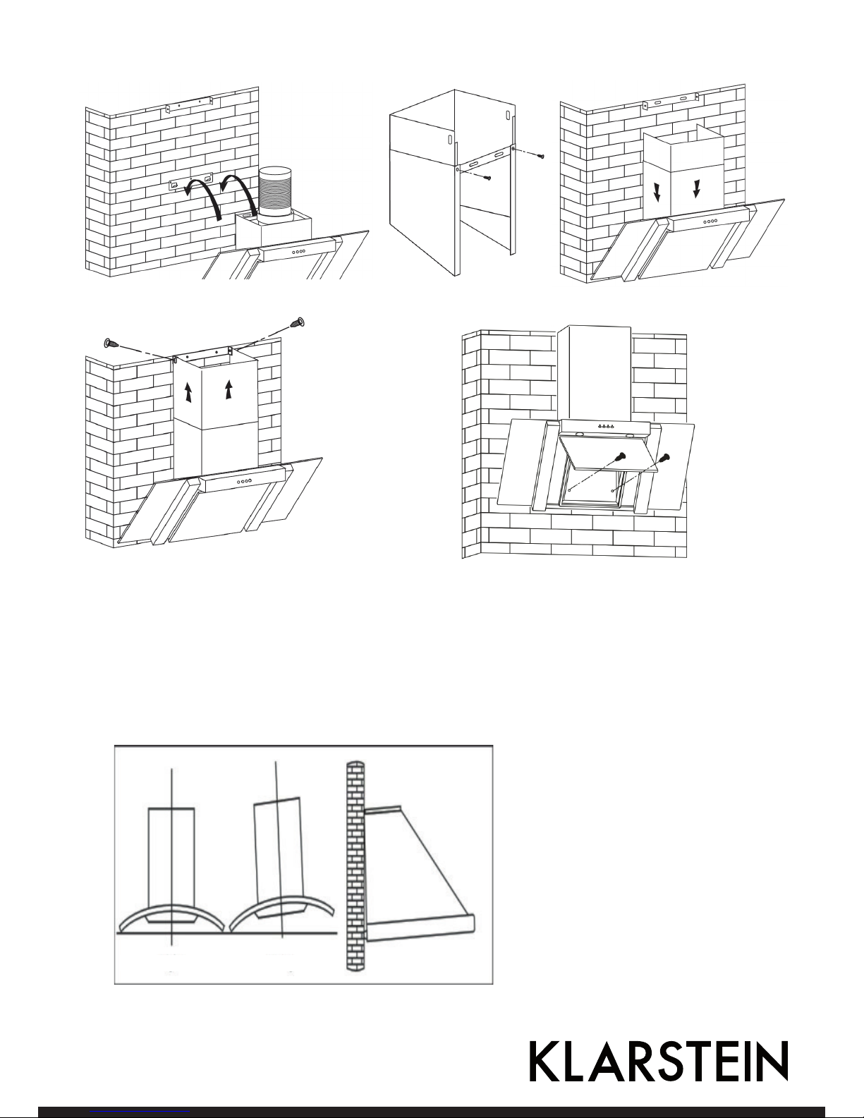
Für das Modell ohne Glas (10030272)
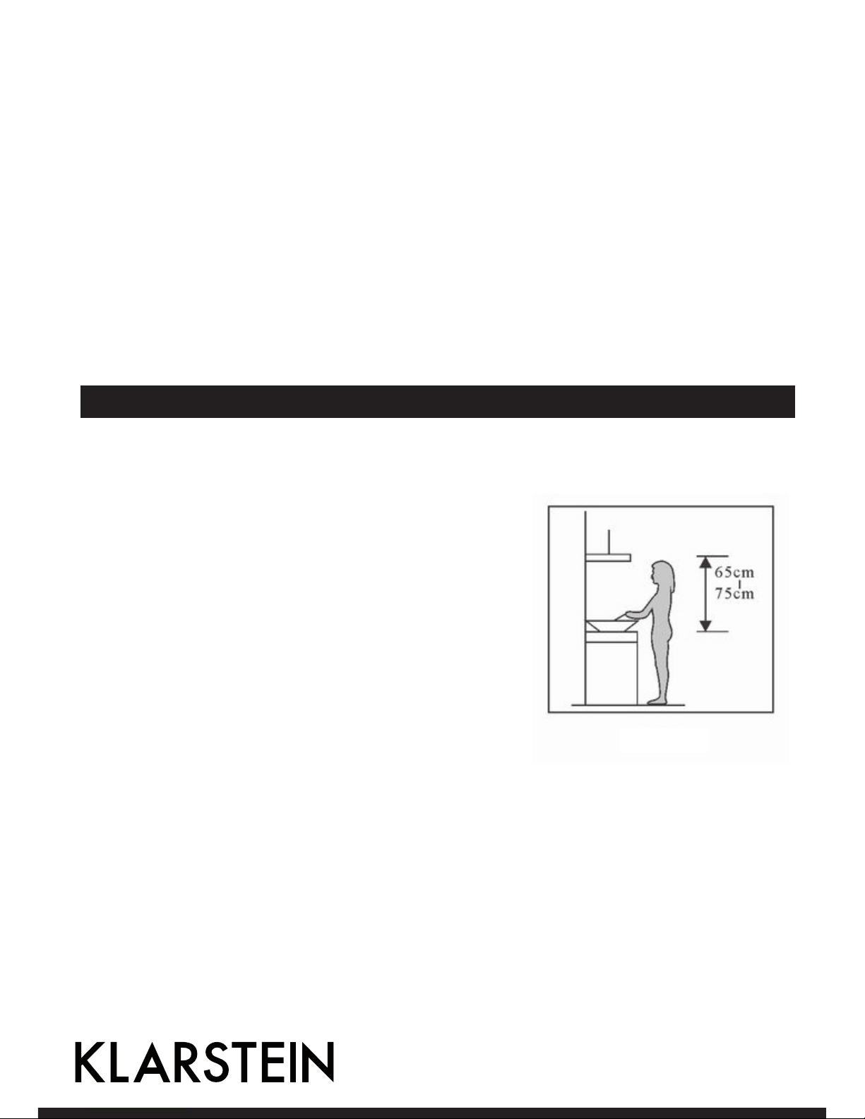
1. Der Abstand zwischen der Kochfläche und der untersten Kante der Dunstabzugshaube muss 65-75 cm
betragen (siehe Bild 1)
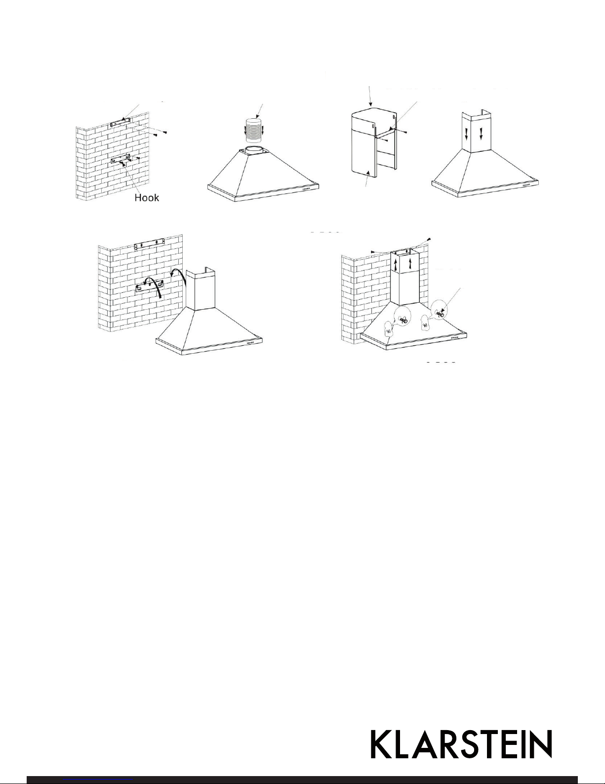
2. Ist die Höhe festgelegt, bringen Sie die Verankerung an der
entsprechenden Stelle an. Dazu müssen Sie zuerst Bohrungen
setzen (Sie benötigen eine Bohrmaschine, passende Bohrer,
Dübel und Schrauben) und anschließend die Verankerung mit
den Schrauben an der Wand befestigen.
3. Nachdem die Verankerung befestigt ist, bringen Sie nach dem
ähnlichen Verfahren die innenliegende Halterung für die Kaminverblendung an (siehe Bild 2). Achten Sie bitte auf den richtigen
Abstand (messen Sie bitte den Abstand aus), da die Kaminverblendung später an der Klammer befestigt wird. Fixieren Sie bitte
die außenliegende Klammer für die Kaminverblendung an der
Außenseite der Verblendung und überprüfen Sie, ob die innere
Kaminverblendung in der Höhe frei beweglich ist. Als nächstes
installieren Sie die Rohrverbindung und die Kaminverblendung
auf der Haube. Siehe
hierzu Bild 3.
4. Setzen Sie die Haube auf die Verankerung (siehe Bild 4).
5. Stellen Sie die richtige Höhe der inneren Kaminverblendung so ein, dass die Halterungen übereinstimmen
und fixieren Sie diese. Danach können Sie die Haube mit den Sicherheitsschrauben befestigen (siehe Bild
5).
Anmerkung: Bitte beachten Sie, dass die zwei Sicherungskappen sich auf der Rückseite des Gehäuses
befinden.
Bild 1
Page 5
5
Bild 2
Halterung für die
Kaminverblendung
Bild 3
Bild 4
Rohrverbindung
Sicherheitsschrauben
Außenseite
Haltung für die Außenverblendung
Innenseite
Bild 5
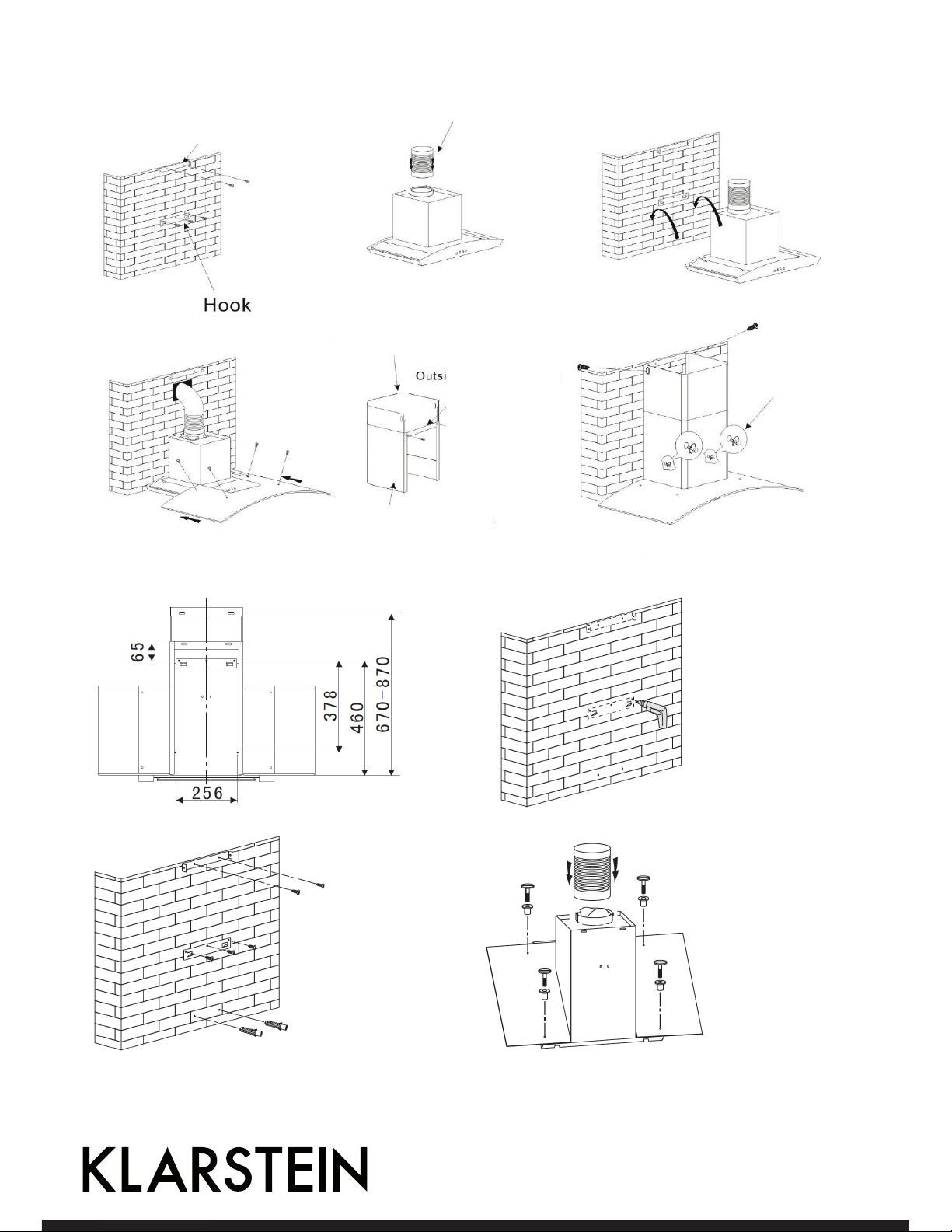
Für das Model mit Glas (10030273)
1. Die Distanz zwischen der Kochfläche und der untersten Kante der Dunstabzugshaube muss
65-75 cm betragen (siehe Bild 1)
2. Ist die Höhe definiert, bringen Sie die Verankerung an der entsprechenden Stelle an. Dazu
müssen Sie zuerst Bohrungen setzen (Sie benötigen eine Bohrmaschine, passende Bohrer, Dübel
und Schrauben) und anschließend die Verankerung mit den Schrauben an der Wand befestigen.
Nachdem die Verankerung fixiert ist, bringen Sie nach dem ähnlichen Verfahren die innenliegende
Halterung für die Kaminverblendung an (siehe Bild 2). Achten Sie bitte auf den richtigen Abstand
(messen Sie bitte den Abstand aus), da die Kaminverblendung später an der Klammer befestigt
wird.
3. Sie die Rohrverbindung und setzen Sie Die Haube auf die Verankerung (siehe Bild 6).
4. Setzen Sie das Glasteil richtig ein und fixieren Sie diese mit den passenden Schrauben. Führen
Sie das Ende der Rohrverbindung ins Freie. Bitte Beachten Sie, dass eine dafür notwendige
Öffnung vorhanden sein muss.
5. Stellen Sie die richtige Höhe der inneren Kaminverblendung ein so, dass die Klammern
übereinstimmen und fixieren Sie diese. Danach können Sie die Haube mit den
Sicherheitsschrauben fixieren(siehe Bild 7).
Anmerkung: Bitte beachten Sie, dass die zwei Sicherheitsventile sich auf der Rückseite des Gehäuses
befinden.
Page 6
6
Bild 2
Halterung für die
Kaminverblendung
Bild 3
Bild 4
Rohrverbindung
Sicherheitsschrauben
Außenseite
Haltung für die
Außenverblen-
dung
Innenseite
Bild 5
Page 7
7
1. Achten Sie vor der Montage darauf, dass der Bereich sauber ist, um das Einsaugen von Rückständen von
Holzsplittern und Staub zu vermeiden.
2. Die Dunstabzugshaube darf sich keinen Abzug mit einem gasbetriebenen Gerät, einem Ofen oder anderer
zugeführter heißer Abluft teilen.
3. Die Biegung des Abluftrohrs 120° nicht überschreiten. Das Rohr kann parallel zum oder über dem Ausgang
spunkt geführt werden und dann zur Wand geführt werden.
4. Gewährleisten Sie nach der Montage, dass die Abzugshaube waagerecht ist, um die Ansammlung von Fettrückständen auf einer bestimmten Seite zu vermeiden.
richtig falsch
Page 8
8
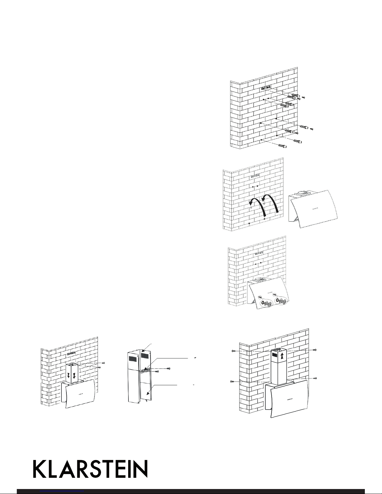
Für das Model 10031905
1. Die Distanz zwischen der Kochfläche und der untersten Kante der Dunstabzugshaube muss
65-75 cm betragen.
2. Ist die Höhe definiert, bringen Sie die Verankerungschrauben an der entsprechenden Stellen an. Dazu
müssen Sie zuerst Bohrungen für die 8 Löcher setzen (Sie
benötigen eine Bohrmaschine, passende Bohrer, Dübel
und Schrauben). Bringen Sie die Dübel und die Verankerungsschrauben an.
3. Hängen Sie die Dunstabzugshaube ein.
4. Verwenden Sie 2 Schrauben (4x30 mm), um die Sicherheitsverriegelungen an der Dunstabzugshaube an der Wand
zu befestigen. (Bild 4)
5. Setzten Sie den Innenkamin in die Halterung des Außenkamins. (siehe Bild 5).
6. Setzen Sie den montierten Kamin auf die Dunstabzugshaube. Befestigen Sie den Außenkamin mit 2 Schrauben (4x8
mm) an der Dunstabzugshaube. Anschließend befestigen
Sie die Außenkaminhalterung mit 2 Schrauben (4x8 mm)
samt Dübeln an der Wand.
7. Heben Sie den Innenkamin an die Wand. Setzen Sie den
Innenkamin an die Innenkaminhalterung. Verwenden Sie
die Schrauben (4x8 mm). Mit dem Außenkamin gehen Sie
ebenso vor.
Innenkamin
Außenkaminhalterung
Außenkamin
Page 9
9
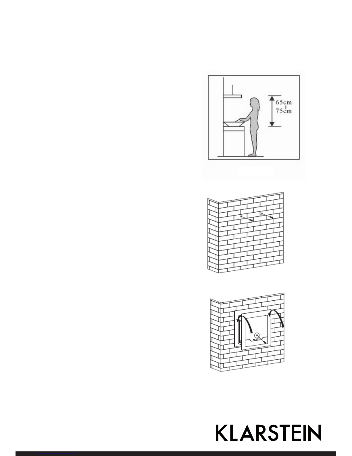
Für das Model 10031910
1. Der Abstand zwischen der Kochfläche und der untersten Kante der Dunstabzugshaube muss 65-75
cm betragen (siehe Bild 1)
2. Ist die Höhe definiert, bringen Sie die Verankerung an der entsprechenden Stelle an. Dazu
müssen Sie zuerst Bohrungen setzen (Sie benötigen eine Bohrmaschine, passende Bohrer, Dübel
und Schrauben) und anschließend die Verankerung
mit den Schrauben an der Wand befestigen.
3. Hängen Sie die Dunstabzugshaube auf die Schrauben. (Bild 2)
4. Verwenden Sie 2 Schrauben des Typs S4x30 mm,
um die Sicherheitsverriegelungen der Dunstabzugshaube an der Wand zu befestigen. (Bild 3)
Bild 1
Bild 3
Bild 2
Page 10
10
Bedienung
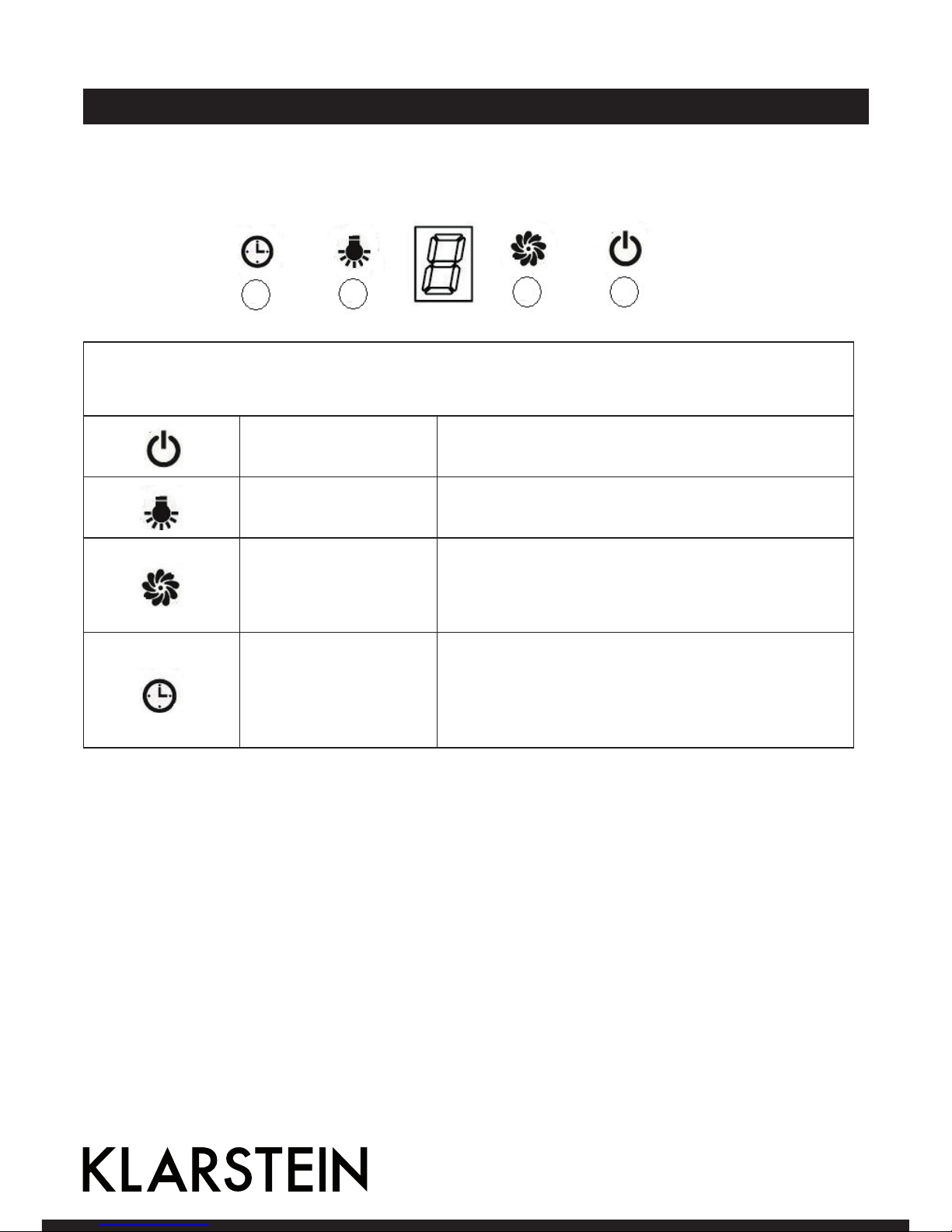
Bedienfeld für Artikelnummer 10030272, 10031905, 10031910
Nach dem Anschluss an die Stromversorgung leuchtet das Bedienfeld auf. Das Gerät geht in den StandbyModus und die Bedienfeld-Beleuchtung erlischt nach 30 Sekunden.
Ein/Aus Ein- und Ausschalten des Ventilators.
Licht Zum Ein- und Ausschalten
Stufe
Es gibt 3 Gebläse-Stufen:
Niedrig (1) - Mittel (2) - Hoch (3). Bei jedem Druck auf die
Taste schaltet der Ventilator um eine Stufe hoch. In der
Anzeige erscheint dann die Stufenzahl (1, 2 oder 3).
Timer
Der Timer ist auf 9 Minuten eingestellt. Drücken Sie
im Betrieb diese Taste, um den Timer für den Motor
einzustellen. In der Anzeige erscheint nacheinander 9,8,
7, 6, bis zur 0. Ohne Eingabe schaltet die Beleuchtung der
Anzeige sich nach 30 Sekunden aus.
Page 11

11
Bedienfeld für Artikelnummer 10030273, 10030274, 10030275, 10031906
0
AUS Schalten Sie mit diesem Knopf die Lüftung aus.
Ventilator
niedrige Stufe
Verwenden Sie die niedrige Stufe zum Durchlüften der Küche. Sie eignet sich
zum Köcheln und Kochen ohne viel Dampf. Erneut drücken, um das Gebläse
auszuschalten.
Ventilator
mittlere Stufe
Die mittlere Stufe ist ideal für das normale Kochen. Erneut drücken, um das
Gebläse auszuschalten.
Ventilator
hohe Stufe
Wählen Sie die hohe Stufe, wenn schwerer Rauch oder Dampf erzeugt wird,
um den höchsten Wirkungsgrad an Abluft zu erreichen. Erneut drücken, um
das Gebläse auszuschalten.
Licht Ein- und Ausschalten der Lampe.
Page 12
12
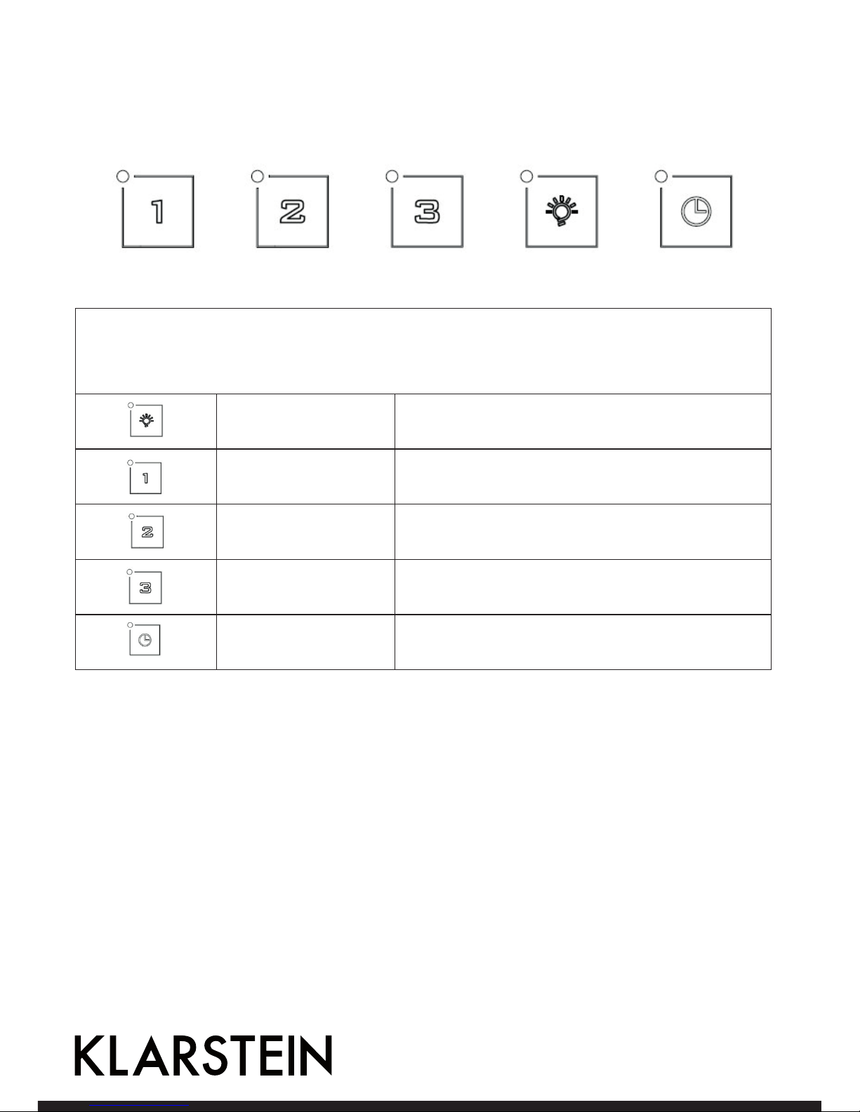
Bedienfeld für Artikelnummer 10030276
Nach dem Anschluss an die Stromversorgung leuchtet das Bedienfeld auf. Das Gerät geht in den StandbyModus und die Bedienfeld-Beleuchtung erlischt nach 5 Sekunden.
Beim Betätigen der jeweilige Taste leuchtet sie.
Licht Zum Ein- und Ausschalten
Niedrige Stufe
Einschalten der niedrigen Stufe. Beim erneuten Druckeauf die Taste geht das Gebläse aus.
Mittlere Stufe
Einschalten der mittleren Stufe. Beim erneuten Druckeauf die Taste geht das Gebläse aus.
Hohe Stufe
Einschalten der mittleren Stufe. Beim erneuten Druckeauf die Taste geht das Gebläse aus.
Timer
Mit dem Drücken der Taste wird der Timer auf 5 Minuten
eingestellt.
Page 13
13
Reinigung und Wartung
Reinigung des Fettfilters
Das Filtergitter besteht aus rostfreiem Stahl. Verwenden Sie daran keine ätzenden Reinigungsmittel. Die Reinhaltung des Filters sorgt für den reibungslosen Betrieb. Befolgen Sie die Hinweise unten genau.
Methode 1
Legen Sie das Gitter in klares warmes Wasser (Temperatur 40-50 °C). Ein Reinigungsmittel hinzugeben und
2-3 Minuten einweichen lassen. Ziehen Sie Schutzhandschuhe an und reinigen Sie das gitter mit einer weichen
Bürste. Üben Sie nicht zu viel Druck aus, da das Gitter empfindlich ist, und leicht beschädigt werden kann.
Methode 2
Den Fettfilter bei 60 °C in den Geschirrspüler geben.
Reinigung der Dunstabzugshaube
• Um das Gehäuse lange Zeit vor Veränderungen zu schützen, sollte die Haube mit warmen Wasser und
einem nicht ätzenden Reiniger gereinigt werden.
• Verwenden Sie keine Scheuermittel, da sie das Gehäuse beschädigen.
• Halten Sie Wasser vom Motor und anderen Teilen fern, da dies das Gerät beschädigen könnte.
• Trennen Sie vor der Reinigung die Stromversorgung .
• Der Aktivkohlefilter darf keiner großen Hitze ausgesetzt werden.
• Reißen Sie nicht die fest angebrachte Leiste um den Aktivkohlefilter herum auf.
• Ersetzen Sie den Netzstecker oder das Netzkabel, wenn sie beschädigt sind.
Page 14

14
Fehlerbehebung
Fehler Grund Lösung
Das Licht brennt, aber der Ventilator läuft nicht.
Das Ventilatorblatt klemmt. Schalten Sie das Gerät aus und
lassen Sie es durch einen qualifizierten Techniker reparieren.
Der Motor ist beschädigt.
Weder Licht noch Ventilator laufen.
Die Glühlampe ist durchgebrannt. Tauschen Sie die Glühlampe aus.
Das Netzkabel ist lose. Stecken Sie das Netzkabel ein.
Starke Vibrationen am Gerät.
Ein Ventilatorblatt ist beschädigt. Schalten Sie das Gerät aus und
lassen Sie es durch einen qualifizierten Techniker reparieren.
Der Motor des Ventilators ist nicht
richtig befestigt.
Schalten Sie das Gerät aus und
lassen Sie es durch einen qualifizierten Techniker reparieren.
Das Gerät hängt nicht richtig in der
Halterung.
Nehmen Sie das Gerät ab und
überprüfen Sie es auf einen einwandfreien Zustand.
Schlechte Abzugsleitung
Der Abstand zwischen dem Gerät
und der Kochplatte ist zu groß.
Repositionieren Sie den Abstand
auf 65-75 cm.
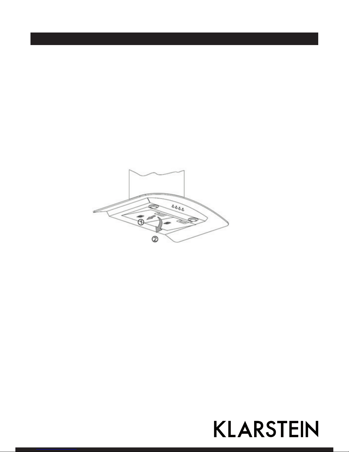
Einsetzen des Aktivkohlfilters
Nehmen Sie den Fettfilter heraus.
Die Kohlfilter befinden sich an beiden Enden des Motors. Drehen Sie die Kohlefilter entegen dem Uhrzeigersinn, bis sie abgedreht sind.
Die Aktivkohlfilter sollten alle 3-6 Monate herausgenommen werden und immer, wenn sie beschädigt sind.
öffnen
schließen
Page 15

15
Hinweise zur Entsorgung
Konformitätserklärung
Befindet sich die linke Abbildung (durchgestrichene Mülltonne auf Rädern) auf dem Produkt,
gilt die Europäische Richtlinie 2012/19/EU. Diese Produkte dürfen nicht mit dem normalen
Hausmüll entsorgt werden. Informieren Sie sich über die örtlichen Regelungen zur getrennten
Sammlung elektrischer und elektronischer Gerätschaften. Richten Sie sich nach den örtlichen
Regelungen und entsorgen Sie Altgeräte nicht über den Hausmüll. Durch die regelkonforme
Entsorgung der Altgeräte werden Umwelt und die Gesundheit ihrer Mitmenschen vor möglichen negativen Konsequenzen geschützt. Materialrecycling hilft, den Verbrauch von Rohstoffen zu verringern.
Hersteller: Chal-Tec GmbH, Wallstraße 16, 10179 Berlin, Deutschland
Dieses Produkt entspricht den folgenden Europäischen Richtlinien:
2014/30/EU (EMV)
2014/35/EU (LVD)
2009/125/EG (EVPG)
-Verordnung (EU) Nr. 66/2014
2010/30/EU (Energieeffizienzkennzeichnung)
-Verordnung (EU) Nr. 65/2014
2011/65/EU (RoHS)
Page 16

16
Contents
Dear Customer,
Congratulations on purchasing this equipment. Please read this manual carefully and take care of the following hints on installation and use to avoid technical damages. Any failure caused by ignoring the items and
cautions mentioned in the operation and installation instructions are not covered by our warranty and any
liability.
Safety Instructions. . . . . . . . . . . . . . . . . . . . . . . . . . . . . 17
Installation . . . . . . . . . . . . . . . . . . . . . . . . . . . . . . . . 18
Operation . . . . . . . . . . . . . . . . . . . . . . . . . . . . . . . . . 24
Cleaning and Maintenance . . . . . . . . . . . . . . . . . . . . . . . . . 27
Troubleshooting . . . . . . . . . . . . . . . . . . . . . . . . . . . . . . 28
Declaration of Conformity . . . . . . . . . . . . . . . . . . . . . . . . . 29
Declaration of Conformity . . . . . . . . . . . . . . . . . . . . . . . . . 29
Page 17

17
Safety Instructions
• These instructions are for your safety. Please read through them thoroughly prior to installation and
retain them for future reference.
Children in the household
• Young children should be kept away. Care should be taken to avoid touching the appliance.
• This appliance can be used by children aged from 8 years and above and persons with reduced physical,
sensory or mental capabilities or lack of experience and knowledge if they have been given supervision
or instruction concerning use of the appliance in a safe way and understand the hazards involved.
Children shall not play with the appliance. Cleaning and user maintenance shall not be made by children
unless they are older than 8 and supervised.
• Keep the appliance and its cord out of reach of children less than 8 years.
General
• The appliance is for domestic use only.
• Accessible parts may become hot during use.
• Do not flame under the range hood.
• Regularly check the power plug and power cord for damage. If the supply cord is damaged, it must be
replaced by the manufacturer, its service agent or similarly qualified persons in order to avoid a hazard.
• Make sure that the power cord is not caught under or in the appliance and avoid damage to the power
cable.
• Do not install the appliance outdoors in a damp place or in an area which may be prone to water leaks
such as under or near a sink unit. In the event of a water leak allow the machine to dry naturally.
Cleaning
• Do not use flammable sprays in close vicinity to the appliance.
• Please dispose of the packing material carefully.
• We also recommend that great care be taken during use and cleaning. Read the cleaning and
maintenance sections for this appliance carefully.
• A steam cleaner is not to be used.
Installation
• All installation work must be carried out by a competent person or qualified electrician.
• This appliance must be installed correctly by a suitably qualified person, strictly following the
manufacturer’s instructions.
• Means for disconnection must be incorporated in the fixed wiring in accordance with the wiring rules.
An all-pole disconnection switch having a contact separation of at least 3 mm in all poles should be
connected in fixed wiring
• Consult local regulations regarding fumes outlets. Do not connect the hood to a fume, ventilation or hot
air duct. Confirm that room ventilation is appropriate with the local authorities. Make sure the maximum
air extraction flow rate for the appliances in the room does not exceed 4 Pa (0.04 mbar). The room must
have adequate ventilation if an extractor hood is used simultaneously with appliances that run on gas or
other fuels. The air must not be discharged into a flue that is used for exhausting fumes from appliances
Page 18

18
Installation
burning gas or other fuels. Regulations regarding air extraction must be complied with.
• Before connecting the hood: switch off the electricity supply and check that the supplied voltage and
frequency coincide with that indicated on the appliance nameplate.
• The hood may stop working during an electrostatic discharge (e.g. lightning). This involves no risk of
damage. Switch off the electricity supply to the hood and reconnect after one minute.
• Do not use the hood if it shows signs of damage or imperfection. Contact customer services.
Models without glass (10030272)
1. The cooker hood should be placed at a distance of 65-75cm (26-30inch) from the cooking surface for the
best effect. See Pic 1.
2. Install the hook on a suitable place once the installation height is
fixed, and keep it in line. The fixed position of the inside chimney
bracket is the place of chimney.
3. Fix the outside chimney bracket on the outside chimney, and
be sure that the inside chimney can be adjusted the height in it
freely as well as fixing the extensible pipe. Afterwards, install the
extensible pipe and chimney on the cooker hood. See Pic 3.
4. Put the cooker hood on the hook. See Pic 4.
5. Adjust the height of the inside chimney to the position of the
inside chimney bracket and fix on it by screw,after ajusting the
position,fix the body with safety screw. See Pic 5.
Note: The two safety vents are positioned on the back casing, with diameter of 6mm.
Page 19

19
For models with glass (10030273)
1. The cooker hood should be placed at a distance of 65-75cm (26-30inch) from the cooking surface for the
best effect. See Pic 1.
2. Install the hook on a suitable place once the installation height is fixed, and keep it in line. The fixed position
of the inside chimney bracket is the place of chimney.
3. Fix the extensible pipe according to the lead direction and way, and then put the cooker hood on the hook.
See pic 3.
4. Put the glass according to the lead direction and way on the cooker hood, and then use the screws to fix the
glass, also lead the extensible pipe outside of the room, meanwhile adjust the height of the inside chimney
to the position of the inside chimney bracket and fix on it by screw , here should be sure the inside chimney
can be flexed freely. See Pic 4.
5. Put the two chimneys together onto the cooker hood body, meanwhile adjust the height of the inside chimney into the suitable height, and fix the inside chimney to the inside chimney bracket by screw. Finally, fix
the body with safety screw. See Pic 5.
Note: The two safety vents are positioned on the back casing, with diameter of 6mm.
Page 20

20
Page 21

21
1. Connect the plug into the power.
2. Press the button “Stop”, the motor is stopped then
3. Press the button “Low”, the motor is running at low speed. Press the button “Mid”, the motor is running at
medium speed. Press the button “High”, the motor is running at high speed.
4. Press the button “Light”, both lights start shining .Press the button again; the lights are switched off then.
Page 22

22
For the model 10031905
1. The cooker hood should be placed at a distance of 65-75cm
(26-30inch) from the cooking surface for the best effect.
2. Install the hanging screw on a suitable place once the installation height is fixed, and keep it in line. The fixed position
of the inside chimney bracket is the place of chimney. Also
install the safety hole in the wall. Total drill 8 holes and insert
the Wall plug. See Pic 2.
3. Hang the cooker hood on wall, See Pic 3.
4. Use 2 screws (4*30mm) to fix the safety locks in the cooker
hood on the wall. See Pic 4.
5. Put the inner chimney inside the outer chimney. Install the
outer chimney bracket on the outer chimney by two screws
(4mm x 8mm). See Pic 5.
6. Put the installed chimneys on the cooker hoods. Fix the outer chimney to the cooker hood by 2 screws (4*8mm), then
fix the outer chimney bracket to the wall by using 2 (4mm x
40mm) screws and wall plugs. See Pic 6.
7. Lift up inner chimney on the wall. Fix the inner chimney to
the inside chimney bracket by using 2 screws (4mm x 8mm).
The same operation to the outer chimney. See Pic 7.
Innenkamin
Außenkaminhalterung
Außenkamin
Page 23

23
Für das Model 10031910
1. The cooker hood should be placed at a distance of
65-75cm (26-30inch) from the cooking surface for
the best effect. See Pic 1.
2. Install the hanging screw on a suitable place once
the installation height is fixed, drill 2 holes and insert the Wall plug.put 2pcs screws(ST4*30mm)into
wall plug, and keep it in line. See Pic 2.
3. Hang the cooker hood on the screws ,
4. Use 2 screws (S4*30mm) to fix the safety locks in
the cooker hood on the wall. See Pic 3
Bild 1
Bild 3
Bild 2
Page 24

24
Operation
Control panel for Item 10030272, 10031905, 10031910
After connecting power to power, the control panel will be lightet. The light will shut off automatically after
30 seconds if without any operation.
On/Off Switches the ventilation on and off.
Light Switches the light on and off.
Ventilation speed
The motor has the low speed, mid. speed and high speed.
When the hood is working with low speed,LED display
will show 1.
Press the botton, then the hood will transfer to the mid
speed for working; the LED will show 2 , press the speed
button again , the hood will transfer to the high speed for
working immediately. And so on..
Timer
This is a 9 minute timer. When the hood is working, press
this button to set a time for motor operation.press the
botton ,LED display will be shown 9.8.7.6 until 0, When
LCD shows 0, After 30 seconds without operation; the
backlight will disappear.
Please note the Lamp is not under control of timer.
Page 25

25
Control panel for Item 10030273, 10030274, 10030275, 10031906
0
OFF Switches the ventilation off.
Low Speed
button
It is used for Ventilation on the kitchen. It is suitable for simmering and cooking which do not make much steam. Press again to stop the motor.
Medium Speed
button
Airflow speed is ideally for ventilation in standard cooking operation. Press
again to stop the motor.
High Speed
button
When high density of smoke or steam produced, press high-speed button for
highest effective ventilation. Press again to stop the motor.
Light button Switching on and off the light.
Page 26

26
Control panel for Item 10030276
Power on: After you have connected the cooker hood to the mains supply the backlight will turn on. The
backlight will turn off after 5s without any operation and hood will enter stand-by mode.
When pressing a key it is lit.
Light Switches light on and off.
Low speed
Push the low button, the indicating light will be lit, and
the motor runs at low speed. Push it again and the motor
will stop.
Mid speed
Push the middle button, the indicating light will be lit,
and the motor runs at mid speed. Push it again and the
motor will stop.
High speed
Push the high button, the indicating light will be lit, and
motor runs on high speed. Push it again and the motor
will stop.
Timer
Whilst the cooker hood is in use, if you press the timer
button once the hood will run for 5 minutes and then
cut off.
Page 27

27
Cleaning and Maintenance
The cleaning of the carbon grease filter mesh
The filter mesh is made of high-density stainless steel. Please do not use the corrosive detergent on it. Keeping
this filter clean will keep the appliance running correctly. Please strictly follow the guidelines below.
Method 1:
Put the mesh into 40-50 c clean water, pour on detergent, and soak for 2-3 mins. Wear gloves and clean with
a soft brush. Please do not apply too much pressure, as the mesh is delicate and will damage easy.
Method 2:
If instructed to do so, it can be put into a dishwasher, set the temperature at around 60 degrees.
Cleaning the cooker hood
• To protect the main body from corrosion over a long period of time, the cooker hood should be cleaned
with hot water plus non corrosive detergent every two months.
• Please do not use abrasive detergent for it will damage the body.
• Keep the motor and other spare parts free from water, as this will cause damage to the appliance.
• Before cleaning the appliance please remember to cut off power
• The carbon filter shouldn’t be exposed to heat.
• Please don’t tear open the fixed bar around the carbon filter.
• If the plug or cord is damaged, please replace it with special soft cord
Page 28

28
Troubleshooting
Installation of the carbon filter
Remove the grease filters
The charcoal filters are located at both end of the motor. Turn the charcoal filters until they are unscrewed.
The carbon filters should be replaced every 3 - 6 months or if they show signs of damage.
Fault Cause Solution
Light on, but fan does not work
The fan blade is jammed. Switch of the unit and repair by quali-
fied service personnel only.
The motor is damaged.
Both light and fan do not work
Light bulb burn Replace the bulb with correct rating.
Power cord looses. Plug in to the power supply again.
Serious Vibration of the unit
The fan blade is damaged. Switch of the unit and repair by quali-
fied service personnel only.
The fan motor is not fixed tightly. Switch of the unit and repair by quali-
fied service personnel only.
The unit is not hung properly on the
bracket.
Take down the unit and check whether
the bracket is in proper location.
Suction performance not good
Too long distance between the unit
and the cooking plane.
Readjust the distance to 65-75 cm.
Page 29

29
Declaration of Conformity
According to the European waste regulation 2012/19/EU this symbol on the product or on
its packaging indicates that this product may not be treated as household waste. Instead it
should be taken to the appropriate collection point for the recycling of electrical and electronic equipment. By ensuring this product is disposed of correctly, you will help prevent potential
negative consequences for the environment and human health, which could otherwise be
caused by inappropriate waste handling of this product. For more detailed information about
recycling of this product, please contact your local council or your household waste disposal
service.
Declaration of Conformity
Producer: Chal-Tec GmbH, Wallstraße 16, 10179 Berlin. Germany
This product is conform to the following European Directives:
2014/30/EU (EM)
2014/35/EU (LVD)
2009/125/EG (ErP)
-Regulation (EU) Nr. 66/2014
2010/30/EU (Energy label)
-Regulation (EU) Nr. 65/2014
2011/65/EU (RoHS)
Page 30

30
Sommaire
Chère cliente, cher client
Toutes nos félicitations pour l’acquisition de ce nouvel appareil. Veuillez lire attentivement les instructions
suivantes de branchement et d’utilisation afin d’éviter d’éventuels dommages. Le fabricant ne saurait être
tenu pour responsable des dommages dus au non-respect des consignes de sécurité et à la mauvaise utilisation de l’appareil.
Consignes de sécurité . . . . . . . . . . . . . . . . . . . . . . . . . . . 31
Montage . . . . . . . . . . . . . . . . . . . . . . . . . . . . . . . . . 32
Fonctionnement. . . . . . . . . . . . . . . . . . . . . . . . . . . . . . 38
Nettoyage et maintenance . . . . . . . . . . . . . . . . . . . . . . . . . 41
Résolution des problèmes . . . . . . . . . . . . . . . . . . . . . . . . . 42
Conseils pour le recyclage . . . . . . . . . . . . . . . . . . . . . . . . . 43
Déclaration de conformité . . . . . . . . . . . . . . . . . . . . . . . . . 43
Page 31

31
Consignes de sécurité
Ce manuel d‘instructions a pour objectif votre sécurité. Lisez attentivement les instructions et conservez
toujours ce manuel dans un endroit sûr pour pouvoir toujours vous y référer.
Enfants à la maison
• Les jeunes enfants doivent être tenus à l‘écart de l‘appareil. Ils doivent être surveillés afin qu‘ils ne
touchent pas les parties chaudes.
• Cet appareil peut être utilisé par des enfants de 8 ans ou plus et des personnes ayant des capacités
et des connaissances physiques, sensorielles et mentales limitées, s‘ils ont reçu des instructions pour
utiliser l‘appareil en toute sécurité et comprennent les risques encourus.
• Tenez l‘appareil et le câble secteur hors de portée des enfants de moins de 8 ans..
Consignes générales
• L‘appareil est destiné à un usage domestique uniquement.
• Les parties accessibles peuvent devenir chaudes pendant le fonctionnement.
• Ne faites pas de flambée sous la hotte.
• Vérifiez régulièrement la prise et le câble d‘alimentation. Si le câble secteur est endommagé, il doit être
remplacé par le fabricant ou le service après-vente pour éviter tout danger.
• Ne laissez pas le câble secteur entrer en contact avec des parties chaudes de l‘appareil.
• Veillez à ne pas coincer le câble secteur sous ou dans l‘appareil pour éviter de l‘endommager.
• N‘installez pas l‘appareil à l‘extérieur, dans un endroit humide ou dans une zone susceptible d‘être
affectée par des fuites d‘eau, par exemple en dessous ou à côté d‘un évier. Laissez l‘appareil sécher
complètement en cas de dégâts des eaux.
Nettoyage
• N‘utilisez aucun spray inflammable à proximité de l‘appareil.
• Éliminez le matériau d‘emballage soigneusement.
• Soyez prudent lorsque vous utilisez et nettoyez l‘appareil. Lisez le chapitre „Nettoyage et entretien“.
• N‘utilisez pas de nettoyeur à vapeur pour le nettoyage.
Montage
• L‘installation doit être effectuée uniquement par un électricien ou un autre technicien qualifié.
L‘assemblage doit être effectué correctement en suivant les instructions du fabricant.
• L‘appareil n‘est pas destiné à être contrôlé par une minuterie externe ou une télécommande.
• Conformément aux directives de câblage le circuit doit comporter une possibilité de coupure
d‘alimentation.
• Prenez connaissance des réglementations locales sur l‘évacuation de la fumée. Ne raccordez pas la hotte
à une cheminée ou à un conduit d‘air chaud. Assurez-vous que la ventilation de la pièce est conforme
aux réglementations locales. Assurez-vous que le débit maximum d‘extraction d‘air des appareils dans
la pièce ne dépasse pas 4 Pa (0,04 mbar). La pièce doit être correctement ventilée lorsque la hotte est
utilisée simultanément avec des appareils brûlant du gaz ou d‘autres combustibles. L‘air ne doit pas être
évacué dans une cheminée qui sert de conduit d‘évacuation pour les appareils brûlant du gaz ou d‘autres
combustibles. Les dispositions légales concernant l‘évacuation doivent être respectées.
Page 32

32
Montage
• Eteignez l‘appareil avant de le brancher. Vérifiez si la tension d‘alimentation correspond à la tension
nominale indiquée sur la plaque signalétique de votre appareil.
• Pendant une décharge électrostatique (par exemple un orage), l‘unité peut cesser de fonctionner. Cela
ne présente pas de danger et n‘endommage pas l‘appareil. Débranchez le câble d‘alimentation de
l‘appareil et rebranchez-la au bout d‘une minute.
• N‘utilisez pas l‘appareil s‘il présente des signes de dommages ou de dysfonctionnements. Dans ce cas,
contactez le service clientèle.
Pour le modèle sans vitre (10030272)
1. La distance entre la surface de cuisson et le bord inférieur de la hotte doit être de 65-75 cm (voir figure 1).
2. Une fois la hauteur déterminée, attachez le support d‘ancrage à
l‘endroit approprié. Pour ce faire, vous devez d‘abord percer des
trous (vous avez besoin d‘une perceuse, de forets adaptés, de
chevilles et de vis), puis fixez le support d‘ancrage au mur à l‘aide
des vis.
3. Une fois le support d‘ancrage fixé, fixez le support interne du parement de cheminée en suivant la même procédure (voir la figure
2). Veuillez être attentif à respecter la distance correcte (vérifiez
les mesures), car le parement de la cheminée sera fixé plus tard
sur ce support. Fixez le support externe du parement de cheminée à l‘extérieur du parement et vérifiez que le parement interne
de la cheminée puisse se déplacer librement sur toute la hauteur.
Ensuite, installez les branchements de tuyaux et le parement de
cheminée sur la hotte. Voir pour cela la figure 3.
4. Installez la hotte sur le support d‘ancrage (voir figure 4).
5. Ajustez la hauteur de la partie interne de la cheminée de manière
à ce que les supports correspondent, puis fixez-les. Ensuite, vous pouvez fixer la hotte avec les vis de
sécurité (voir figure 5).
Remarque : veuillez noter que les deux bouchons de sécurité sont situés sur le dos du châssis.
figure 1
Page 33

33
figure 2
crochet
support du parement
de cheminée
figure 3
figure 4
connecteur de tuyau
vis de sécurité
face extérieure
support de parement externe
face intérieure
figure 5
Für das Model mit Glas (10030273)
1. La distance entre la surface de cuisson et le bord inférieur de la hotte doit être de 65-75 cm (voir figure 1).
2. Une fois la hauteur déterminée, attachez le support d‘ancrage à l‘endroit approprié. Pour ce faire, vous devez
d‘abord percer des trous (vous avez besoin d‘une perceuse, de forets adaptés, de chevilles et de vis), puis
fixez le support d‘ancrage au mur à l‘aide des vis. Une fois le support d‘ancrage fixé, fixez le support interne
du parement de cheminée en suivant la même procédure (voir la figure 2). Veuillez être attentif à respecter
la distance correcte (vérifiez les mesures), car le parement de la cheminée sera fixé plus tard sur ce support.
3. Montez le connecteur de tuyau et placez la hotte sur le support d‘ancrage (voir figure 6)..
4. Installez soigneusement la partie en verre et fixez-la avec les vis appropriées. Faites passer l‘extrémité de la
connexion de tuyau à l‘extérieur. Veuillez noter qu‘une ouverture est pour cela nécessaire et doit donc être
présente.
5. Ajustez la hauteur de la partie interne de la cheminée de manière à ce que les supports correspondent, puis
fixez-les. Ensuite, vous pouvez fixer la hotte avec les vis de sécurité (voir figure 7).
Remarque : veuillez noter que les deux bouchons de sécurité sont situés sur le dos du châssis.
Page 34

34
figure 2
support du parement de che-
minée
figure 3
figure 4
connecteur de tuyau
Sicherheitsschrauben
face extérieure
support de parement externe
face intérieure
figure 5
crochet
Page 35

35
1. Avant le montage, assurez-vous que la zone est propre pour éviter d‘aspirer les débris de copeaux de bois
et de la poussière.
2. La hotte ne doit pas partager une évacuation d‘air avec un appareil alimenté au gaz, un four ou un autre
appareil produisant de l‘air chaud.
3. Ne dépassez pas 120° pour le coude du tube d‘évacuation. Le tube peut être guidé parallèlement ou au-dessus de la sortie, puis dirigé vers le mur.
4. Après l‘installation, assurez-vous que la hotte est à niveau pour éviter l‘accumulation de résidus de graisse
sur un seul côté.
correct incorrect
Page 36

36
Pour le modèle 10031910
1. La distance entre la surface de cuisson et le bord inférieur de
la hotte doit être de 65-75 cm (voir figure 1)
2. Une fois la hauteur définie, attachez le support d‘ancrage à
l‘endroit approprié. Pour ce faire, vous devez d‘abord percer
des trous (vous avez besoin d‘une perceuse, de forets adaptés, de chevilles et de vis), puis fixer le support d‘ancrage au
mur à l‘aide des vis.
3. Accrochez la hotte sur les vis. (figure 2)
4. Utilisez 2 vis S4x30 mm pour fixer les verrouillages de sécurité de la hotte au mur. (figure 3)
cheminée intérieure
support de
cheminée extérieure
cheminée extérieure
Page 37

37
Pour le modèle 10031910
1. La distance entre la surface de cuisson et le bord
inférieur de la hotte doit être de 65-75 cm (voir
figure 1)
2. Une fois la hauteur définie, attachez le support
d‘ancrage à l‘endroit approprié. Pour ce faire, vous
devez d‘abord percer des trous (vous avez besoin
d‘une perceuse, de forets adaptés, de chevilles et
de vis), puis fixer le support d‘ancrage au mur à
l‘aide des vis.
3. Accrochez la hotte sur les vis. (figure 2)
4. Utilisez 2 vis S4x30 mm pour fixer les verrouillages de sécurité de la hotte au mur. (figure 3) .
figure 1
figure 3
figure 2
Page 38

38
Fonctionnement
Panneau de commande pour les articles de numéros 10030272, 10031905, 10031910
Lorsque vous branchez l‘appareil sur l‘alimentation, le panneau de commande s‘allume. L‘appareil passe en
mode veille et l‘éclairage du panneau de commande s‘éteint au bout de 30 secondes.
marche/arrêt Démarrer et arrêter le ventilateur.
éclairage Pour allumer et éteindre la lumière
vitesse
Il y a 3 vitesses de ventilateur :
Faible (1) – moyenne (2) – rapide (3). Chaque fois que vous
appuyez sur le bouton, le ventilateur passe à la vitesse
supérieure. Le numéro de la vitesse apparaît alors sur
l'affichage (1, 2 ou 3).
minuterie
La minuterie est réglée sur 9 minutes. En cours de
fonctionnement, appuyez sur ce bouton pour régler la
minuterie du moteur. L'écran affichera 9,8, 7, 6 successivement, jusqu'à 0. En l'absence de saisie, l'éclairage de
l'affichage s'éteint au bout de 30 secondes.
Page 39

39
Panneau de commande pour les articles de numéros 10030273, 10030274, 10030275, 10031906
0
arrêt Eteignez le ventilateur avec ce bouton.
Ventilateur basse
vitesse
Utilisez la vitesse lente pour ventiler la cuisine. Celui-ci convient pour mijoter
et cuire sans beaucoup de vapeur. Appuyez à nouveau pour éteindre le
ventilateur.
ventilateur vitesse moyenne
La vitesse moyenne est idéale pour la cuisson normale. Appuyez à nouveau
pour éteindre le ventilateur.
ventilateur
vitesse rapide
Sélectionnez la vitesse rapide lorsque de la fumée ou de la vapeur d'eau est
générée afin d'atteindre l'efficacité d'évacuation la plus élevée. Appuyez à
nouveau pour éteindre le ventilateur.
Eclairage Allumer ou éteindre la lampe.
Page 40

40
Panneau de commande pour l‘article numéro 10030276
Une fois l‘appareil branché sur l‘alimentation, le panneau de commande s‘allume. L‘appareil passe en mode
veille et l‘éclairage du panneau avant s‘éteint au bout de 5 secondes.
Il s‘allume lorsque vous appuyez sur un bouton.
Eclairage Allumer ou éteindre
Basse vitesse
Allumez le ventilateur à basse vitesse. Lorsque vous appuyez à nouveau sur le bouton, le ventilateur s'éteint.
Vitesse moyenne
Allumez l'étape intermédiaire. Lorsque vous appuyez à
nouveau sur le bouton, le ventilateur s'éteint.
Vitesse rapide
Allumez le ventilateur à vitesse moyenne. Lorsque vous
appuyez à nouveau sur le bouton, le ventilateur s'éteint.
Minuterie Une pression sur le bouton règle la minuterie à 5 minutes.
Page 41

41
Nettoyage et maintenance
Nettoyage du filtre à graisses
La grille de filtre est en acier inoxydable. N‘utilisez pas de produits de nettoyage corrosifs. La propreté du filtre
assure un bon fonctionnement. Suivez les instructions ci-dessous attentivement.
Méthode 1
Placez la grille dans de l‘eau chaude et claire (température 40-50°C). Ajoutez un détergent et laissez tremper
pendant 2-3 minutes. Portez des gants de protection et nettoyez la grille avec une brosse douce. Ne pas appliquer trop de pression car la grille est fragile et peut facilement être endommagée.
Méthode 2
Mettez le filtre à graisse dans le lave-vaisselle à 60 °C.
Nettoyage de la hotte aspirante
• Pour conserver le boîtier dans son état d‘origine pendant une longue période, nettoyez le capot à l‘eau
chaude avec un nettoyant non corrosif.
• N‘utilisez pas d‘agents abrasifs car ils endommageraient le boîtier.
• Tenez l‘eau à l‘écart du moteur et des autres pièces, car cela pourrait endommager l‘appareil.
• Débranchez l‘alimentation avant le nettoyage.
• Le filtre à charbon actif ne doit pas être exposé à une chaleur excessive.
• Ne pas rompre la bande fixée autour du filtre à charbon.
• Remplacez la fiche d‘alimentation ou le cordon d‘alimentation s‘ils sont endommagés.
Page 42

42
Résolution des problèmes
Problème Cause Solution
La lumière est allumée mais le ventilateur ne fonctionne pas.
La pale du ventilateur est coincée. Éteignez l'appareil et faites-le
réparer par un technicien qualifié.
Le moteur est endommagé.
Ni la lumière ni le ventilateur ne
fonctionnent.
L'ampoule a grillé. Remplacez l'ampoule.
Le câble d'alimentation est mal
branché.
Rebranchez le câble secteur.
Fortes vibrations de l'appareil.
Une pale du ventilateur est endommagée.
Éteignez l'appareil et faites-le
réparer par un technicien qualifié.
Le moteur du ventilateur est mal
fixé.
Éteignez l'appareil et faites-le
réparer par un technicien qualifié.
L'appareil est mal fixé sur ses
supports.
Décrochez l'appareil et vérifiez qu'il
est en parfait état.
Mauvaise puissance d'aspiration
La distance entre l'appareil et
les plaques de cuisson est trop
importante.
Réajustez l'écart à 65-75 cm.
Installation du filtre à charbon actif
Retirez le filtre à graisse.
Les filtres à charbon sont situés aux deux extrémités du moteur. Tournez les filtres à charbon dans le sens
antihoraire jusqu‘à ce qu‘ils soient dévissés.
Les filtres à charbon actif doivent être retirés tous les 3-6 mois et chaque fois qu‘ils sont endommagés.
ouvrir
fermer
Page 43

43
Conseils pour le recyclage
Déclaration de conformité
Le pictogramme ci-contre apposé sur le produit signifie que la directive européenne
2012/19/UE (DEEE) s’applique (poubelle à roues barrée d’une croix). Ces produits ne peuvent
être jetés dans les poubelles domestiques courantes. Renseignez-vous concernant les règles
appliquées pour la collecte d’appareils électriques et électroniques. Conformez-vous aux réglementations locales et ne jetez pas vos anciens produits avec les ordures ménagères. Le
respect des règles de recyclage des vieux produits aide à la protection de l’environnement et
de la santé de votre entourage contre les conséquences négatives possibles. Le recyclage des
matériaux aide à réduire l’utilisation des matières premières.
Fabricant : Chal-Tec GmbH, Wallstraße 16, 10179 Berlin, Allemagne
Ce produit est conforme aux directives européennes suivantes :
2014/30/UE (CEM)
2014/35/UE (LVD)
2009/125/CE (EVPG)
- Réglementation (UE) N° 66/2014
2010/30/UE (étiquetage de l‘efficacité énergétique)
- Réglementation (UE) N° 65/2014 2011/65/UE (RoHS)
 Loading...