

Page 1
Deckenventilator
10029347 10029348
Page 2
Sehr geehrter Kunde,
wir gratulieren Ihnen zum Erwerb Ihres Gerätes. Lesen Sie die folgenden Hinweise sorgfältig durch und befolgen Sie diese, um möglichen Schäden vorzubeugen. Für Schäden, die durch Missachtung der Hinweise und
unsachgemäßen Gebrauch entstehen, übernehmen wir keine Haftung.
Technische Daten
Artikelnummer 10029345, 10029346
Stromversorgung 220-240 V~ 50-60 Hz
Sicherheitshinweise
• Befestigen Sie den Ventilator nicht an der Steckdose, sondern nur an der Decke.
• Der minimale Abstand zwischen Boden und Rotorblättern sollte 2,3 Meter betragen. Der Haken, an dem der
Ventilator hängt, muss einer Mindestbelastung von 100 kg standhalten.
• Der Ventilator muss durch einen zweipoligen Schalter mit mindestens 3 mm Kontaktöffnungsweite in der
Gebäudeinstallation geschützt werden.
• Installieren Sie nur passende Birnen.
• Schalten Sie den Strom ab, bevor Sie den Ventilator anschließen oder reparieren.
• Der Ventilator muss geerdet sein, um Stromschläge zu vermeiden.
• Bringen Sie den Ventilator nicht in feuchten oder nassen Räumen an.
• Seien Sie vorsichtig, wenn Sie Arbeiten in der Nähe der Rotorblätter ausführen.
• Lassen Sie den Ventilator von einem Elektriker oder einer ähnlich qualifizierten Person installieren.
• Kinder, physisch und körperlich eingeschränkte Menschen sollten das Gerät nur benutzen, wenn sie vorher
von einer Aufsichtsperson ausführlich mit den Funktionen und den Sicherheitsvorkehrungen vertraut gemacht wurden. Achten Sie darauf, dass Kinder nicht mit dem Ventilator spielen.
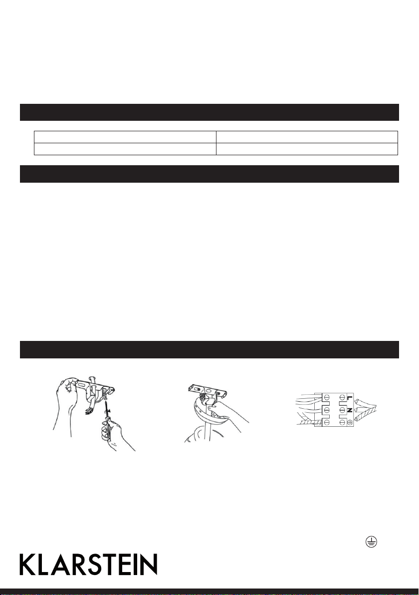
1. Befestigen Sie die Montageplatte mit zwei Schrauben, Federringen und Unterlegscheiben
an einem Deckenbalken. Der
Deckenbalken muss stark genug
sein das Gewicht des beweglichen Ventilators zu tragen.
Montage
2. Befestigen Sie die VentilatorBauteile an der Montageplatte. Richten Sie das Kugelgelenk des Ventilators an der
Aufhänglasche der Montageplatte aus.
3. Schließen Sie die Kabel von
der Stromquelle und der
Montagehalterung zu den
Anschlussklemmen folgendermaßen an:
Braunes Kabel: “L”
Blaues Kabel: “N”
Grün/Gelbes Kabel:
2
Page 3
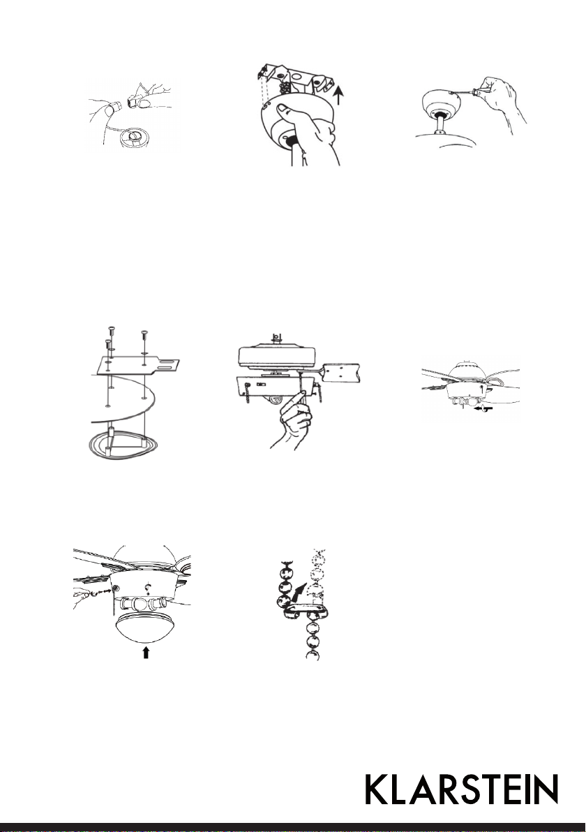
4. Verbinden Sie die Lampenkabel, indem sie die zwei Plastikanschlüsse zusammenstecken, bis sie einrasten.
5. Richten Sie die Seitenlöcher
der Abedeckung an den Klammern aus. Heben Sie die Abedeckung an, bis die Schrauben
zum Boden der Schlitze reichen. Drehen Sie die Abedeckung im Uhrzeigersinn, bis
sich die Schrauben in der in
der Aussparung befinden.
6. Schieben Sie die Abdeckung
über die Montageplatte. Achten Sie darauf, dass Sie dabei
keine Kabel abklemmen.
7. Befestigen Sie den Flügelhalter
und die Abdeckplatte mit drei
Schrauben und Federscheiben
am Ventilatorflügel.
10. Ziehen Sie alle Schrauben fest
und versichern Sie sich, dass
der Schirm fest sitzt und dass
keine Kabel eingeklemmt
sind. Befestigen Sie die Nylonkette am Führungsstift der
oberen Halterung.
3
8. Befestigen Sie die Ventilatorhalterung mit Federringen und
Schrauben am Motor.
11. Befestigen Sie die beiden Zugschnüre, und versichern Sie
sich, dass die Halteklammer
die Schnur richtig hält.
9. Befestigen Sie die Birnen an
der Lampenfassung (max. 42 W
E27, nicht im Lieferumfang
enthalten).
Page 4
Inbetriebnahme und Bedienung
• Schalten Sie den Strom ein, bevor Sie den Ventilator starten.
• Der Ventilator startet, sobald Sie den 3-Stufen-Schalter bedienen, der über die Verlängerungskette mit dem
Motor verbunden ist.
• Ziehen Sie an der Verlängerungskette des Lichtschalters, um das Licht ein- und auszuschalten.
Der Ventilator dreht sich mit 3 verschiedenen Geschwindigkeiten, je nachdem wie oft sie an der Verlängerungskette ziehen:
• Einmal ziehen = hohe Geschwindigkeit
• Zweimal ziehen = mittlere Geschwindigkeit
• Dreimal ziehen = Niedrige Geschwindigkeit
• Viermal ziehen = Aus
Mit dem Schalter am Motorgehäuse lässt sich die Richtung des Luftstroms beeinflussen, den die Rotorblätter
erzeugen.
• Kaltes Wetter: Stellen Sie den Schalter auf RIGHT, damit die Blätter die warme Luft unter der Decke in den
Raum darunter verteilen.
• Warmes Wetter: Stellen Sie den Schalter auf LEFT, damit die Blätter einen kühlenden Luftstrom erzeugen
und in den Raum verteilen.
HINWEIS: Versichern Sie sich, dass die Rotorblätter zum Stehen gekommen sind, bevor Sie die Richtung der
Rotorblätter ändern. Damit Sie sich und den Motor nicht beschädigen, sollte der Schalter auf UP oder DOWN
stehen, wenn der Ventilator läuft.
Entsorgung und Konformitätserklärung
Befindet sich die linke Abbildung (durchgestrichene Mülltonne auf Rädern) auf dem Produkt, gilt die Europäische Richtlinie 2002/96/EG. Diese Produkte dürfen nicht mit dem
normalen Hausmüll entsorgt werden. Informieren Sie sich über die örtlichen Regelungen
zur getrennten Sammlung elektrischer und elektronischer Gerätschaften. Richten Sie sich
nach den örtlichen Regelungen und entsorgen Sie Altgeräte nicht über den Hausmüll.
Durch die regelkonforme Entsorgung der Altgeräte werden Umwelt und die Gesundheit
ihrer Mitmenschen vor möglichen negativen Konsequenzen geschützt. Materialrecycling
hilft, den Verbrauch von Rohstoffen zu verringern.
Hersteller: Chal-Tec GmbH, Wallstraße 16, 10179 Berlin, Deutschland.
Dieses Produkt entspricht den folgenden Europäischen Richtlinien:
2014/30/EU (EMV)
2014/35/EU (LVD)
2011/65/EU (RoHS)
4
Page 5

Dear Customer,
Congratulations on purchasing this equipment. Please read this manual carefully and take care of the following
hints to avoid damages. Any failure caused by ignoring the mentioned items and cautions mentioned in the
instruction manual are not covered by our warranty and any liability.
Technical Data
Item number 10029345, 10029346
Power supply 220-240 V~ 50-60 Hz
Safety Instructions
• Never attach the fan to a power point, but to the ceiling itself.
• The minimum distance between the blades of the fan and the floor must be 2.3m. The minimum carrying
capacity of the hook from which the fan is hung must be 100kg.
• Make sure to install all poles disconnection switch having a contact separation of at least 3mm between
poles in the supply wiring to the ceiling fan.
• Install only bulbs of the type intended for your fan.
• Switch off the power before connecting or repairing the fan.
• The fan must be properly grounded to avoid the risk of electric shocks.
• Never mount the fan in a moist or wet room. Be careful when working near the rotating blades.
• Always have your fan installed by someone who is knowledgeable about electrical wiring.
• This appliance is not intended for use by persons (including children) with reduced physical. Sensory or
mental capabilities, or lack of experience and knowledge, unless they have been given supervision or instruction concerning use of the appliance by a person responsible for their safety. Page 1 of 3 Children should
be supervised to ensure that they do not play with the appliance.
1. Secure the mounting plate to
a ceiling joist with two screws,
spring washers and flat washers
provided. Ensure the support
for the mounting plate must be
capable of safely and securely
holding the moving weight of
the fan.
5
Mounting
2. Hang the fan assembly onto
the mounting plate. The
mounting plate has a lug on
it; this should be lined up with
the corresponding groove on
the fan assembly ball joint.
3. Connect wires from supply
and bracket to the wiring
terminals as follow:
Brown wire
Blue wire
Green/yellow wire:
Page 6

4. Connect the internal lead to
the fan body by clipping together the two plastic male /
female connectors are firmly
clicked together.
5. Attach canopy to the bracket
by aligning canopy side holes
with the bracket side holes.
Lift fan until the screws reach
the bottom of the slots and
then rotate the canopy counterclockwise until the screws
drop into the slot recesses
6. Insert the other two set screws
and washers. Tighten all the
screws, make sure that the
canopy is secure and that you
have not trapped any wires.
Ensure that the slot of the
nylon ball hanger fits into the
guide pin of the upper canopy.
7. Assemble blades shanks and
decorative plate onto fan
blades using three screws and
spring washers each.
10. Insert the other two set screws
and washers. Tighten all the
screws, make sure that the
canopy is secure and that
you have not trapped any
wires. Ensure that the slot of
the nylon ball hanger fits into
the guide pin of the upper
canopy.
8. Install the fan blade sets onto
the motor by tightening the
screws and spring washers.
11. Attach the two pull cords, ensure that the pull cord retaining
clips supports the cord.
9. Install light bulb (max 42W E27
not supplied) to the lampholder
6
Page 7

Use and Operation
• Turn electricity on before the fan start to work.
• The fan starts to operate when pulling the Three-speed Switch connected by an extension chain on the
motor housing.
• Pulling the “ON/OFF” Light Switch connected by an extension chain on the motor housing can control the
turning on or off of the light.
The fan can be in different speeds as pulling the Three-speed Switch:
• The first pulling = HIGH SPEED
• The second pulling = MEDIUM SPEED
• The third pulling = LOW SPEED
• The fourth pulling = OFF
The switch on motor housing for controlling the fan blades rotating direction controls the direction of air movement.
• Cold weather: Push the switch “UP” so that the blades will bring the warm air trapped near the ceiling fan to
move downwards throughout the room.
• Hot weather: Push switch “DOWN”so that the blades will create a breeze and circulate the air to the room.
Note: Do make sure that the fan stops operating before using the Direction Switch. In order to prevent any
damage to the motor or injury to you, the switch should stay at the UP or DOWN
position when the fan is working.
Disposal and Declaration of Conformity
According to the European waste regulation 2002/96/EC this symbol on the product
or on its packaging indicates that this product may not be treated as household waste.
Instead it should be taken to the appropriate collection point for the recycling of electrical
and electronic equipment. By ensuring this product is disposed of correctly, you will help
prevent potential negative consequences for the environment and human health, which
could otherwise be caused by inappropriate waste handling of this product. For more detailed information about recycling of this product, please contact your local council or your
household waste disposal service.
Producer: Chal-Tec GmbH, Wallstraße 16, 10179 Berlin, Germany.
This product is conform to the following European Directives:
2014/30/EU (EMC)
2014/35/EU (LVD)
2011/65/EU (RoHS)
7
Page 8

Chère cliente, cher client,
Toutes nos félicitations pour l’acquisition de ce nouvel appareil. Veuillez lire attentivement et respecter les
instructions de ce mode d’emploi afin d’éviter d’éventuels dommages. Nous ne saurions être tenus pour responsables des dommages dus au non-respect des consignes et à la mauvaise utilisation de l’appareil.
Fiche technique
Numéro d’article 10029345, 10029346
Alimentation électrique 220-240 V~ 50-60 Hz
Consignes de sécurité
• Ne pas fixer le ventilateur à la prise électrique, seulement au plafond.
• La distance minimale entre le sol et les pales de rotor doit être de 2,3 mètres. Le crochet auquel est suspendu le ventilateur doit pouvoir supporter une charge minimale de 100 kg.
• Le ventilateur doit être protégé par un interrupteur bipolaire avec une ouverture de contact d’au minimum 3
mm dans l’installation électrique du bâtiment.
• Installer uniquement les ampoules adaptées.
• Éteindre le courant avant de raccorder le ventilateur ou de le réparer.
• Le ventilateur doit être relié à la terre pour éviter tout risque d’électrocution.
• Ne pas installer le ventilateur dans des pièces humides ou mouillées.
• L’utilisateur doit être vigilant s’il travaille à proximité des pales de rotor.
• Faire installer le ventilateur par un électricien ou par une personne de qualification analogue.
• Les enfants ainsi que les personnes aux capacités physiques et mentales réduites ne doivent pas utiliser
l’appareil à moins d’avoir assimilé dans le détail les consignes d‘utilisation et de sécurité données par la personne chargée de les surveiller. S’assurer que les enfants ne jouent pas avec le ventilateur.
1. Fixer la plaque de montage avec
deux vis, deux rondelles élastiques et deux rondelles à une
solive. La solive doit être suffisamment solide pour supporter
la charge du ventilateur en mouvement.
Montage
2. Fixer la tige du ventilateur à la
plaque de montage. Aligner la
coupole du ventilateur avec
les encoches d’accrochage de
la plaque de montage.
3. Relier le câble d’alimentation
au moteur grâce au domino,
en respectant l’ordre suivant :
Câble marron : « L »
Câble bleu : « N »
Câble jaune/vert :
8
Page 9

4. Raccorder les câbles de la
lampe en branchant et encliquetant les deux connecteurs
en plastique.
5. Aligner les encoches latérales
de la coupole avec les attacher. Soulever la coupole jusqu’à
ce que les vis se trouvent en
bas de la fente. Puis tourner
la coupole dans le sens des
aiguilles d’une montre jusqu’à
ce que les vis se trouvent dans
l’encoche de verrouillage.
6. Fixer la coupole à la plaque de
montage. Veiller à ce qu’aucun
câble ne se déconnecte pendant l’opération.
7. Fixer les supports des pales et
les caches avec trois vis et trois
rondelles élastiques aux pales
du ventilateur.
10. Visser toutes les vis et s’assurer
que l’abat-jour est bien fixé et
qu’aucun câble n’est déconnecté. Attacher la chaînette
en nylon à l’axe de guidage du
support du haut..
9
8. Fixer le support du ventilateur
avec des rondelles élastiques
et des vis au moteur.
11. Fixer les deux cordelettes et
s’assurer que l’attache les tient
bien.
9. Installer les ampoules (max. 42
W E27, non fournies) dans les
douilles de lampe.
Page 10

Mise en marche et utilisation
• Mettre le courant avant de démarrer l’appareil.
• Le ventilateur démarre à partir du moment où l’interrupteur à 3 vitesses est actionné par la chaînette de
prolongation reliée au moteur.
• Tirer sur la chaînette de prolongation de l’interrupteur de lumière pour éteindre ou allumer la lumière.
Le ventilateur permet trois vitesses de rotation, en fonction du nombre de fois où l’on tire sur la chaînette :
• Tirer une fois = grande vitesse
• Tirer deux fois = vitesse moyenne
• Tirer trois fois = vitesse faible
• Tirer quatre fois = éteindre
L’interrupteur au niveau du moteur permet d’influencer la direction du courant d’air produit par le mouvement
des pales.
• Par temps froid : mettre l’interrupteur sur RIGHT pour que les pales propagent l’air chaud du plafond vers le
bas de la pièce.
• Par temps chaud : mettre l’interrupteur sur LEFT pour que les pales produisent un courant d’air froid et le
propagent dans toute la pièce.
REMARQUE : s’assurer que les pales se sont arrêtées de tourner avant de modifier la direction des pales. Afin
de ne pas endommager le moteur, l’interrupteur doit être sur UP ou DOWN pendant la rotation du ventilateur.
Recyclage et déclaration de conformité
Vous trouverez sur le produit l’image ci-contre (une poubelle sur roues, barrée d‘une croix),
ce qui indique que le produit se trouve soumis à la directive européenne 2002/96/CE.
Renseignez-vous sur les dispositions en vigueur dans votre région concernant la collecte
séparée des appareils électriques et électroniques. Respectez-les et ne jetez pas les appareils usagés avec les ordures ménagères. La mise au rebut correcte du produit usagé permet de préserver l’environnement et la santé. Le recyclage des matériaux contribue à la
préservation des ressources naturelles.
Fabricant : Chal-Tec GmbH, Wallstraße 16, 10179 Berlin, Allemagne.
Ce produit est conforme aux directives européennes suivantes :
2014/30/UE (CEM)
2014/35/UE (LVD)
2011/65/UE (RoHS)
10
Page 11

Gentile cliente,
La ringraziamo per aver acquistato il nostro prodotto. La preghiamo di leggere attentamente le seguenti istruzioni e di seguirle per evitare eventuali danni. Non ci assumiamo alcuna responsabilità per danni derivati da una
mancata osservazione delle avvertenze di sicurezza e da un uso improprio del dispositivo
Dati tecnici
Numero articolo 10029345, 10029346
Alimentazione 220-240 V~ 50-60 Hz
Avvertenze di sicurezza
• Non collegare il ventilatore alla presa di corrente, bensì al soffitto.
• La distanza minima tra il pavimento e le pale deve essere di 2,3 metri. Il gancio al quale il ventilatore è fissato
deve poter reggere un peso di almeno 100 kg.
• Collegare il cavo di alimentazione ad un interruttore bipolare con distanza tra i contatti di apertura di almeno
3 mm.
• Installare solo lampadine idonee.
• Staccare la corrente prima di installare o di riparare il ventilatore.
• Per evitare scosse elettriche, il ventilatore deve essere collegato ad una presa dotata di messa a terra.
• Non installare il ventilatore in ambienti umidi o bagnati.
• Prestare attenzione quando si eseguono lavori in prossimità delle pale in movimento.
• Far installare il ventilatore da un elettricista o da una persona qualificata.
• I bambini, le persone con limiti fisici e mentali possono usare il dispositivo solo se un supervisore ha prima
spiegato loro l’utilizzo e le norme di sicurezza.
• Assicurarsi che i bambini non giochino con il ventilatore.
1. Fissare la piastra di montaggio
alla trave del soffitto utilizzando
due viti, le rondelle elastiche e
le rondelle. La trave del soffitto
deve essere abbastanza resistente per reggere il peso del ventilatore in movimento.
11
Montaggio
2. Fissare i componenti del ventilatore alla piastra di montaggio. Allineare il giunto sferico
del ventilatore alla piastra di
montaggio.
3. Collegare alla morsettiera i
cavi della fonte di alimentazione e della staffa di
montaggio come segue:
Cavo marrone: “L”
Cavo blu: “N”
Cavo verde/giallo:
Page 12

4. Collegare i cavi interni assemblando i due connettori in
plastica fino al loro completo
inserimento.
5. Assemblare la calotta alla
staffa di montaggio allineando i fori laterali della calotta
con i fori laterali della staffa
di montaggio. Sollevare la
calotta finché le viti raggiungono le scanalature. Avvitare
la calotta in senso orario fino
all’inserimento delle viti nelle
apposite scanalature.
6. Far scorrere la calotta sulla piastra di montaggio. Prestare
attenzione a non disconnettere i cavi.
7. Fissare il sopporto per le
pale e la piastra decorativa
utilizzando le rosette elastiche
e le viti.
10. Serrare tutte le viti e assicurarsi che il paralume sia
fissato correttamente e di
non aver incastrato i cavi.
8. Fissare il supporto del ventilatore al motore utilizzando le
rondelle elastiche e le viti.
11. Fissare entrambe le catene di
comando e assicurarsi che il
morsetto di fissaggio sorregga
la catena di comando.
9. Fissare le lampadine al
portalampada (max. 42 W E27
non incluse nella consegna).
12
Page 13

Messa in funzione e utilizzo
• Prima di mettere in funzione il ventilatore, collegarlo alla corrente.
• Il ventilatore si mette in funzione dopo aver premuto l’interruttore a 3 velocità posto sulla catena di comando collegata al motore.
• Per accendere e spegnere la luce, tirare la catena di comando dell’interruttore della luce.
Il ventilatore funziona con 3 diverse velocità impostabili tirando la catena di comando:
• Una volta = velocità alta
• Due volte= velocità media
• Tre volte= velocità bassa
• Quattro volte= spento
È possibile direzionare la corrente dell’aria con l’interruttore posto sul motore.
• Se fa freddo: posizionare l’interruttore su UP affinché le pale possano distribuire l’aria calda nella stanza.
• Se fa caldo: posizionare l’interruttore su DOWN affinché le pale possano produrre e distribuire un flusso
d’aria fresco nella stanza.
NOTA: assicurarsi che le pale si arrestino prima di modificare la loro direzione. Per non danneggiare il motore,
l’interruttore deve essere posizionato su UP o DOWN quando il ventilatore è in funzione.
Smaltimento e dichiarazione di conformità
Se sul prodotto è presente la figura a sinistra (il cassonetto dei rifiuti mobile sbarrato), si
applica la direttiva europea 2002/96/CE. Questi prodotti non possono essere smaltiti con
i rifiuti normali. Informarsi sulle disposizioni vigenti in merito alla raccolta separata di dispositivi elettrici ed elettronici. Non smaltire i vecchi dispositivi con i rifiuti domestici. Grazie
al corretto smaltimento dei vecchi dispositivi, si proteggono il pianeta e la salute delle persone da possibili conseguenze negative. Il riciclo di materiali aiuta a ridurre il consumo di
materie prime.
Produttore: Chal-Tec GmbH, Wallstraße 16, 10179 Berlino, Germania.
Questo prodotto è conforme alle seguenti direttive europee:
2014/30/UE (EMC)
2014/35/UE (LVD)
2011/65/UE (RoHS)
13
 Loading...