

Page 1
User Manual
DM8000 DSP Designer Software
Advanced Digital Audio Processor for Installation Applications with Confi gurable DSP,
Audio Networking and Acoustic Echo Cancellation
Page 2

2 DM8000 User Manual
Table of Contents
1. Installation ................................................................ 3
1.1 System Requirements ........................................................ 3
1.2 Installation Procedure ....................................................... 3
2. Software Interface Overview ................................... 3
2.1 Basic Screen Elements ....................................................... 3
3. Module Library ........................................................ 12
3.1 Input Output Modules .................................................... 12
3.2 Mixers.................................................................................... 15
3.3 Equalisers ............................................................................. 19
3.4 Filters ..................................................................................... 21
3.5 CrossOvers .......................................................................... 23
3.6 Dynamics ............................................................................. 23
3.7 Routers .................................................................................27
3.8 Delays ...................................................................................28
3.9 Controls ................................................................................ 28
3.10 M e ters ................................................................................. 36
3.11 Generators ......................................................................... 38
4. Building a Signal Processing Architecture ............ 39
4.1 Deploying Component Objects .................................. 40
5. Operation ................................................................. 41
5.1 Networking ......................................................................... 41
5.2 System Security ................................................................. 41
5.3 Third Party Control ........................................................... 43
6. Index ......................................................................... 58
LIMITED WARRANTY
For the applicable warranty terms and conditions and additional information
regarding MUSIC Group’s Limited Warranty, please see complete details online at
music-group.com/warranty.
Page 3

3 DM8000 User Manual
1. Installation
1.1 System Requirements
Minimum Hardware
PC-based Hardware
Recommended Operating Systems
Windows*
* Windows is ei ther a registere d trademark or tra demark of Microsof t Corporati on in the United States
and/or other countries.
A PC computer running DM8000 DSP Designer Software with Windows®
operating systems must have a 10/100 BaseT network card (NIC) installed.
Ethernet switches must be 10/100 BaseT compatible, with sufficient ports for
connection to each DM8000 unit (multiple switches may be used).
For more inf ormation about DM 8000 netwo rking see “Networ king” on pgs. 38-39.
1.2 Installation Procedure
To install the DM8000 DSP Designer sof tware:
1. Go to the DM8000 product page at
http://www.music-group.com/brand/klarkteknik.
2. Click on the Downloads tab.
-Core 2 DU O CPU
-Ethernet port
-1 GB RAM
-Windows 7, 32-bit of 64-bit
-Window s 8, 32-bit or 64 bit
2.1.1 Main Screen
Here is the Main Screen you should see when you open and load the sof tware:
DM8000 Main Screen
The main screen of the DM8000 soft ware has several sections:
2.1.2 Build Window
The Build Windowoccupies the largest portion of the main screen, at
the lower-right. This is the area where system design actually occurs,
with the placement and connec tion of Component Objects.
3. Click on the download icon for the latest version of the DM8000 DSP
Designer software.
4. Read the software End User License Agreement and click on “Agree”.
5. Click on “Download”.
6. Click on the downloaded .exe le and follow the installation instructions.
2. Software Interface Overview
2.1 Basic Screen Elements
The DM8000 DSP Designer software deploys an interface structure similar to
software geared toward visual design, with standard pulldown menus, toolbars
and libraries.
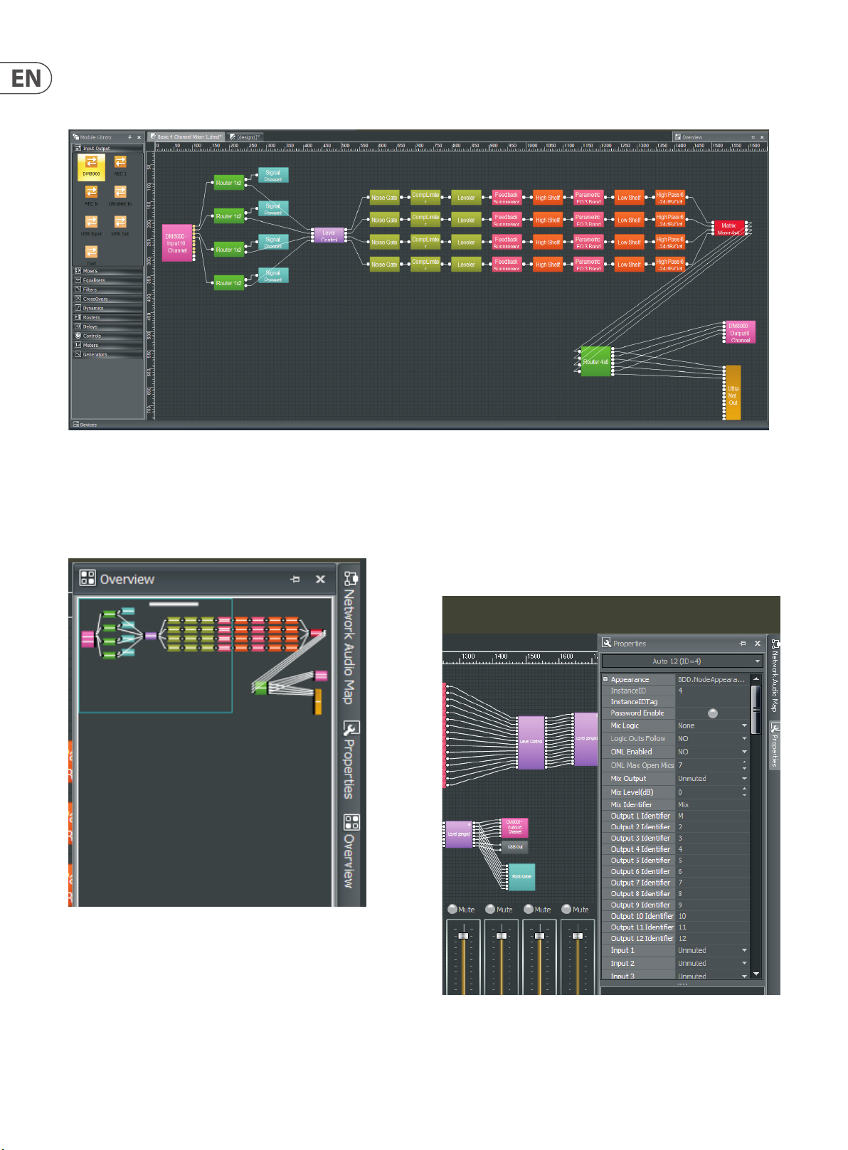
DM8000 Build Window
Page 4
4 DM8000 User Manual
2.1.3 Component Objects
Component Objects represent the individual hardware devices and signal processing elements contained within processing Modules.
Component Objects appear specifically within the Build Window whenever a processing Module is dragged in and placed within the Build Window.
Build Window with Component Objects
2.1.4 Overview Screen
The Overview Screen is available to aid navigation if a system becomes too big
to fit inside the available Build Screen space (the Overview Screen is on the right
side of the Main Screen).
2.1.5 Properties Screen
The Properties Screen appears at the lower-left of the main screen and
provides an editable table of attributes regarding the Build Window and its
associated Component Objects. The Properties Screen is a handy way to edit
multiple attributes of a selected Component Object without launching a
Dialog Box.
DM8000 Overview Screen
DM8000 Properties Screen
Page 5
5 DM8000 User Manual
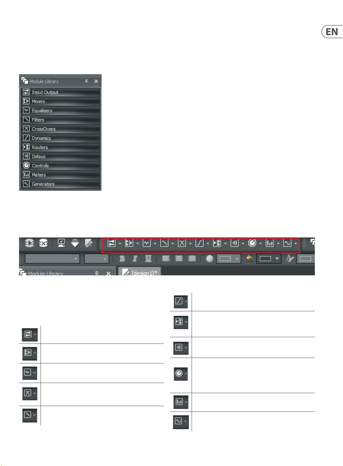
2.1.6 Module Library Panel
The Module Library of available Component Objects is displayed at the lowerleft of the main screen for drag-and-drop placement into the Build Window.
If needed, the ModuleLibrary can be closed to increase the width of the Build
Window. When the Module Library is closed, Component Objects can then be
selected and placed into the Build Window by using the Module Library Toolbar.
DM8000 M odule Library S creen
2.1.7 Module Library Toolbar
The Module Library Toolbar is located directly above the Build Window. Each icon in the toolbar represents a separate category of Processing Modules. Processing
Modules can also be selected in the Module Library Toolbar for placement into the Build Window.
Module Library Toolbar
Module Library Toolbar Elements
The Module Library Toolbar contains icons representing the following categories
of Processing Modules (for more detailed explanations of the Processing Modules
functionality, see “Module Library” on pgs. 13-35):
Input Output modules for routing audio signals into and out of
Dynamics provide Leveler, CompLimiter, Ducker, Noise Gate, and
ANC (Ambient Noise Compensator) functions
Routers offer audio routing and switching func tions from
simple source selection and signal-splitting to complicated input/
output matrices
the DM8000 DSP
Delays provide audio time delay functions for applications such as
Mixers provide typical audio mixing functions with several
time alignment of loudspeakers over distance
sub-categories
Controls offer more detailed channel strip functions than
Equalisers provide both graphic and parametric equalisation,
as well as feedback suppression
the Router and Source Selection modules. These functions
include more flexible level control, phase inversion, muting,
logic-controlled switching and ‘ganging’ of multiple inputs to a
Filters provide High Pass, Low Pass, High Shelf, Low Shelf and
All-Pass filters for applications that require rolling off of
frequencies, simple tone controls, or phase compensation
single fader
Meters provide Signal Present, Peak, RMS, and
Logic Meter functions
CrossOvers provide 2-way, 3-way and 4-way crossover functions
Generators provide sine-wave, sweep, pink-noise, and white-
noise generator functions
Page 6
6 DM8000 User Manual
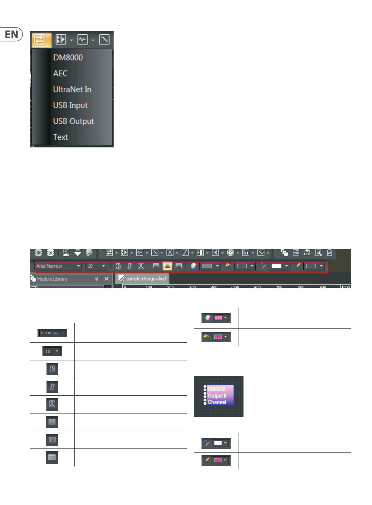
Input Out put Toolbar Pulldown M enu
Each of the above Module Library Toolbar icons has a matching pulldown menu
showing the various sub-categories of Processing Modules.
To place a Processing Module from the Module Library Toolbar into the Build
Window, click on the desired categor y in the pulldown menu and then place the
cursor into the Build Window and click. After clicking, the system will drop the
relevant Component Objects into the Build Window’s grid.
2.1.8 Format Toolbar
The Format Toolbar allows you to customize text and colors used in Component Objects in the Build Window. The Format Toolbar elements are only active when a
specific Component Object is selected. Multiple Component Objects can be selected at once for text and color editing.
Format Toolbar
Format Toolbar Elements
ForeColor sets the foreground color of the
Component Object
Font allows you to choose the font type from a
pulldown menu
Font Size determines the point size of the text in the
selected Component Object
Bold renders the selected text with a thicker look
NOTE: When the selected Component Object has different ForeColor and
Background colors, the system will create a gradient look with the selected
foreground color at the top and the selected background color at the bottom.
Background Color sets the background color of the
Component Object
for emphasis
Italic renders the selected tex t with a slanted look
Underline places a line underneath the selected text
Left Justify aligns the selected text along the lef t of
the Component Object
Center aligns the selected text along the middle axis of
the Component Object
Right Justify aligns the selected text along the right
edge of the Component Object
Component Object with ForeColor/Background Gradient
Text Color sets the color of the text in the selected
Component Object
Border Color sets the color for the border line around
the edges of the selected Component Object
Page 7
7 DM8000 User Manual
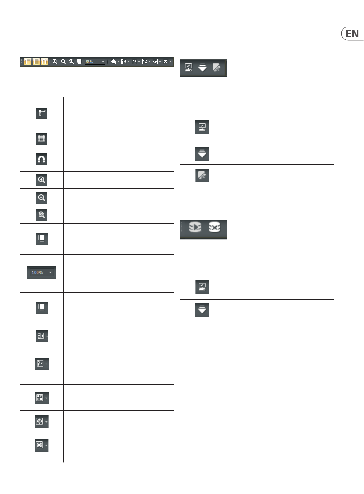
2.1.9 Build Toolbar
The Build Toolbar controls certain aspects of the Build Window, such as the
grid, rulers, zooming and alignment of Component Objects.
Build Toolbar
Build Toolbar Elements
Ruler Bar places a ruler along the left and top sides of
the Build Window for precise placement of Component
Objects. Moving cursor lines inside the rulers show
exact coordinates
Grid On activates a grid in the background of the
Build Window
Snap to Grid causes Component Objects to “stick” to
the grid as the Component Objects are moved around
inside the Build Window
Zoom In increases the magnification of the Build
Window to make Component Objects bigger
Zoom Out decreases the magnification of the Build
Window so Component Objects appear smaller
Zoom 1:1 returns Component Objects to their standard,
default size in the Build Window
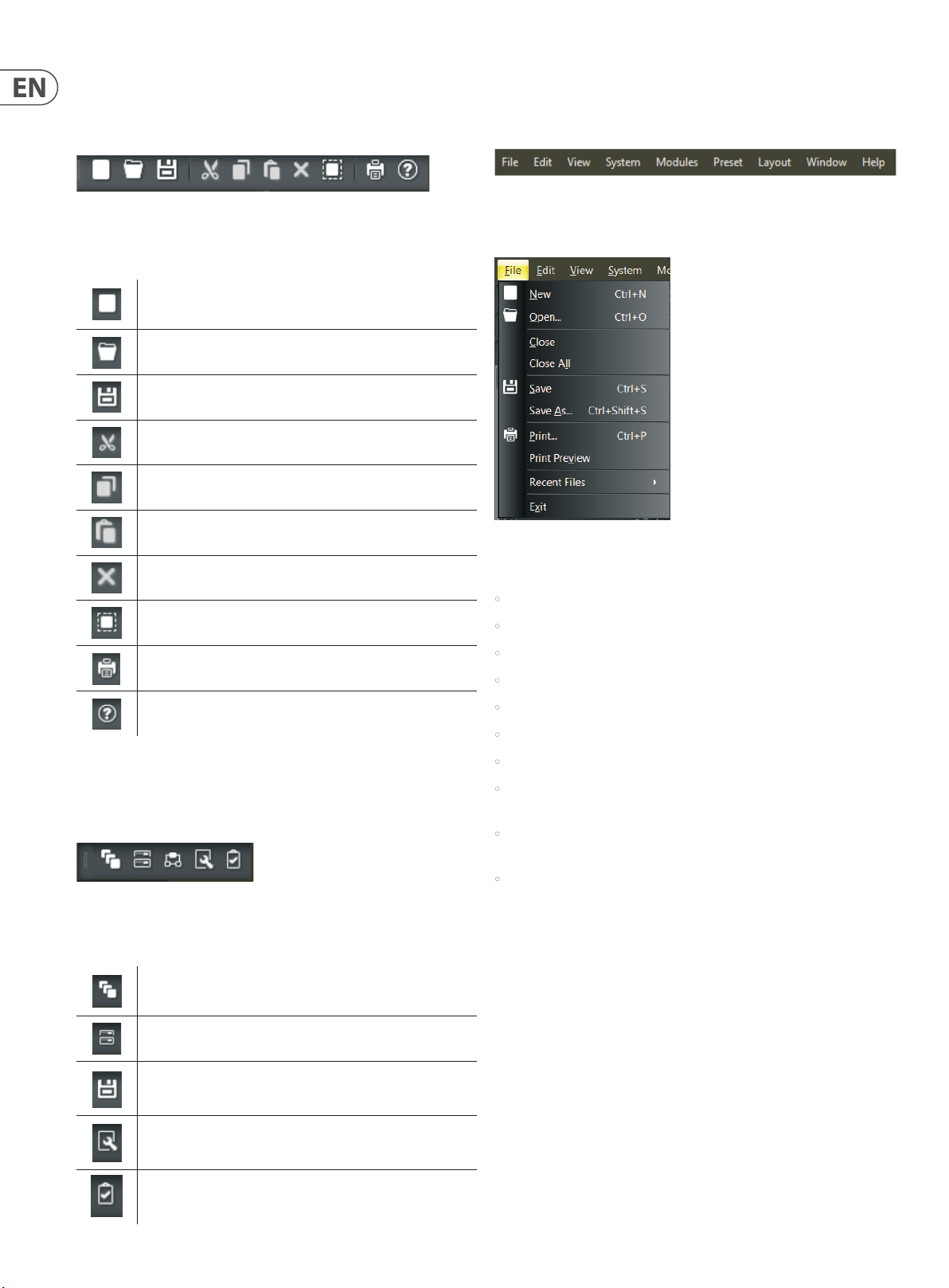
2.1.10 DSP Operation Toolbar
The DSP Operation Toolbar contains functions for Compile, Download,
Edit Mode, and so on.
DSP Operation Toolbar
DSP Operation Toolbar Elements
Compile prepares your design to run on the DSP, checks
the design for problems, notifies you of errors that need
to be corrected, and calculates the percentage of DSP
resources in use
Download Design to Device sends the compiled
design to the DSP processor
Enter Editing Mode
2.1.11 Network Toolbar
The Network Toolbar contains functions related to starting and stopping
network connections.
Zoom to Fit automatically alters magnification in
the Build Window so that an entire Signal Processing
Architecture will be visible and fit inside the
Build Window
Zoom to Scale of fers a pulldown menu so that you can
immediately jump to a specif ic magnification setting
(50%, 75%, 100%, 125%, 150%, and so on). You may
also type the desired magnification setting directly into
the Zoom to Scale window
Order contains fur ther sub-commands for changing
the stacking order of Component Objects in the Build
Window, including Bring to Front, Send to Back,
Bring Forward and Send Backward
Pack Objects removes spaces and arranges
Component Objects as tightly as possible along the left,
right, top or bottom edges of a group of objec ts
Align Objects straightens a group of objects along
the left, right, top, or bottom edges of the group of
objects. You may also align a group of objects by using
Horizontal Center or Vertical Middle commands
Space Evenly equalizes the spacing in a group
of objects by using Across, Down, Vertical or
Horizontal commands
Network Toolbar
Network Toolbar Elements
Start Network Service activates network connections
to compile and install DSP designs, update firmware
and run audio through the network
Stop Network Service shuts down your network
Center in View moves the selected object or objects to
the center of the Build Window
Make Same Size will make a group of Component
Objects all appear the same size. This function typically
will make all objects in the group the same size as the
smallest object in the selected group
Page 8
8 DM8000 User Manual
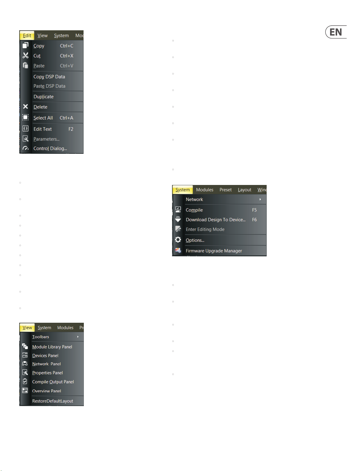
2.1.12 Standard Toolbar
The Standard Toolbar contains file functions such as New, Open and Save, plus
additional editing functions such as Cut, Copy, Paste, Print and Help.
Standard Toolbar
Standard Toolbar Elements
New begins a new .dmd file
Open opens an existing .dmd file
Save saves the current .dmd file
Cut removes selected text and objec ts from the Build Window and
places the cut material into the clipboard
Copy makes a copy of selected text and objects, and places the
copied material into the clipboard
Paste places material from the clipboard into the
selected location
2.1.14 Main Menus
Main Menus provide all of the toolbar functions mentioned above via pulldown
menus, with several more in-depth editing functions.
Main Menus
Main Menu Elements
File Pulldown Menu
Delete removes selec ted text or objects from the Build Window
Select All automatically selects every object in the Build Window
Print sends out a hardcopy rendering of the currently ac tive
design in the Build Window to a printer
Content launches Help files
2.1.13 View Toolbar
The View Toolbar allows you to quickly launch various panels including the
Module Library Panel, Device Panel, Network Panel, Proper ties Panel and the
Compile Output Panel.
View Toolbar
View Toolbar Elements
Module Library launches the Module Library screen
File Pulldown Menu contains the following commands:
• New creates a new .dmd le.
• Open opens an existing .dmd le.
• Close closes the current .dmd le open in the Build Window.
• Close All closes all currently open .dmd tabs in the Build Window.
• Save saves the current .dmd le.
• Save As allows you to save the current .dmd le and designate a le name.
• Print prints out a hardcopy of the current design in the Build Window.
• Print Preview lets you view the current design as it will appear in the
printout before you print.
• Recent Files opens an additional pulldown menu with a list of recent .dmd
les available for quick selection.
• Exit shuts down the DSP Designer software.
Device Panel launches the Device Panel
Network Panel launches the Network Panel
Properties Panel launches the Properties screen
Compile Output launches the Compile Output screen
Page 9
9 DM8000 User Manual
Edit Pulldown Menu
View Pulldown Menu contains the following commands:
• Toolbars launches an additional menu showing which toolbars are currently
selected and visible. Currently-selected toolbars appear with a check mark.
• Module Library Panel launches the Module Librar y panel on the left side
of the Main Screen.
• Device Panel launches a panel with a list of devices currently connected to
the DSP Designer software.
• Network Panel launches the Network Audio Map on the right side of the
Main Screen.
• Properties Panel launches a Properties window for the currently-selected
Component Object in the Build Window.
• Compile Output Panel opens a window that shows results and feedback
from the Compile command.
• Overview Panel launches a window on the right side of the Main Screen
that shows the entire design currently in the Build Window. The Overview
Panel is useful when a design exceeds the available space in the current
Build Window.
Edit Pulldown Menu contains the following commands:
• Copy makes a copy of selected text and objects, and places the copied
material into the clipboard.
• Cut removes selected text and objects from the Build Window and places
the cut material into the clipboard.
• Paste places material from the clipboard into the selected location.
• Copy DSP Data
• Paste DSP Data
• Duplicate
• Delete removes selected text or objects from the Build Window.
• Select All automatically selects every object in the Build Window.
• Edit Text lets you access and edit text in the currently-selec ted Component
Object in the Build Window.
• Parameters launches the Parameters Dialog Box for the currently-selec ted
Component Object in the Build Window.
• Control Dialog launches the Control Dialog Box for the currently-selected
Component Object in the Build Window.
• RestoreDefaultLayout re-congures the Main Window with the default
toolbars and other screens.
System Pulldown Menu
System Pulldown Menu contains the following commands:
• Network launches an additional menu with the Start Network Service and
Stop Network Service commands (also contained in the Network Toolbar).
• Compile prepares your design to run on the DSP, checks the design for
problems, noties you of errors that need to be corrected, and calculates the
percentage of DSP resources in use.
• Download Design To Device sends the compiled design to the
DSP processor.
View Pulldown Menu
• Enter Editing Mode
• Options launches an additional window with a tab for General settings
(Enable toolbar customization and Log debug info) and a Network tab for
selecting the Default Network Interface Card.
• Firmware Upgrade Manager launches a window to enable rmware
updates for multiple devices in your network.
Page 10
10 DM8000 User Manual
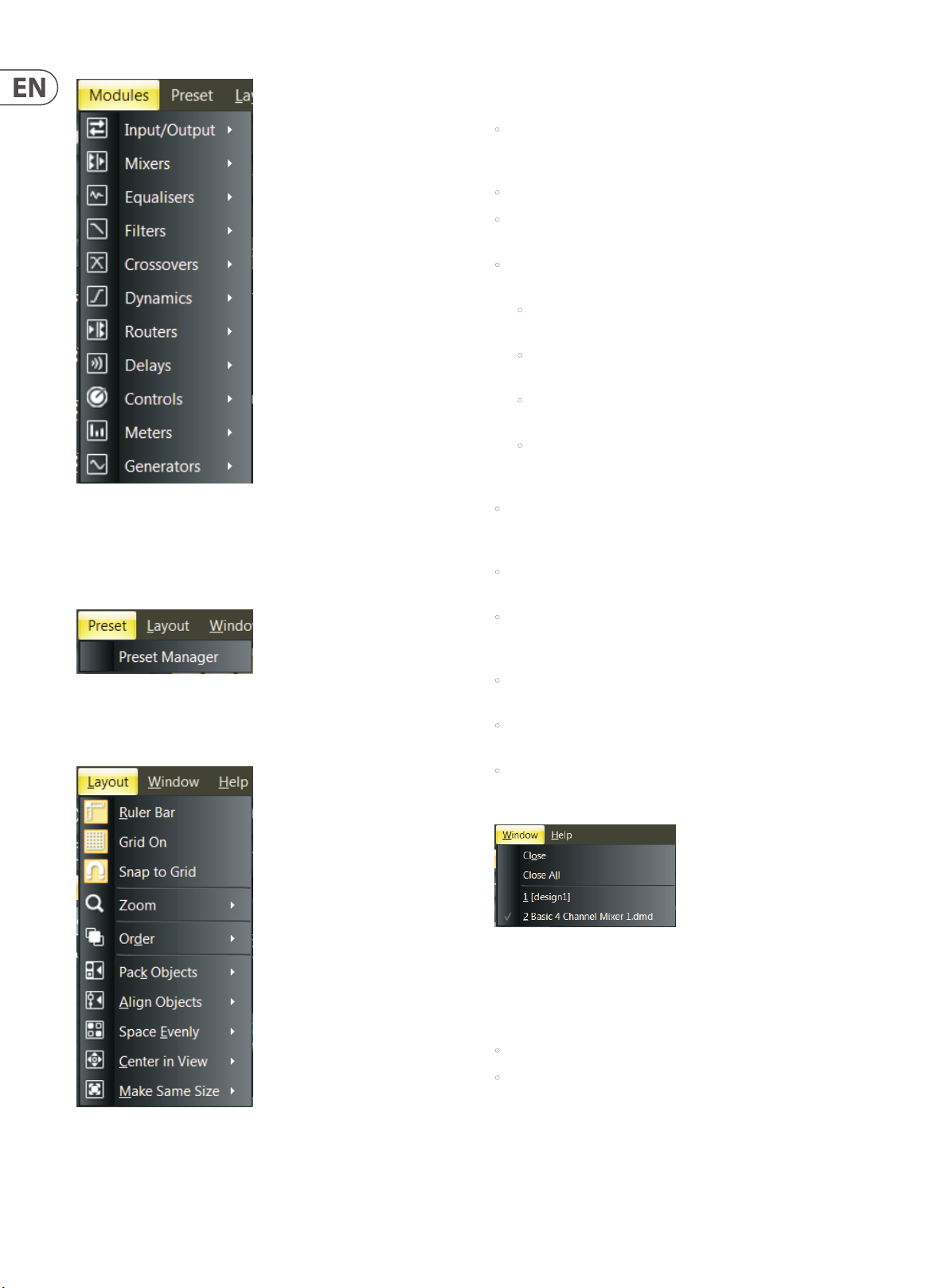
Modules Pulldown Menu
Modules Pulldown Menu contains multiple sub-menus for choosing and
placing Processing Modules into the Build Window. This menu is a third option
for placing Modules, in addition to the Module Library Toolbar (see pgs. 16-17)
and the Module Library Panel (see pg. 6).
Layout Pulldown Menu contains and repeats the following commands from
the Build Toolbar:
• Ruler Bar places a ruler along the left and top sides of the Build Window
for precise placement of Component Objects. Moving cursor lines inside the
rulers show exact coordinates.
• Grid On activates a grid in the background of the Build Window.
• Snap to Grid causes Component Objects to “stick” to the grid as the
Component Objects are moved around inside the Build Window.
• Zoom has an additional sub-menu with all of the Zoom commands from the
Build Toolbar:
• Zoom In increases the magni cation of the Build Window to make
Component Objects bigger.
• Zoom Out decreases the magni cation of the Build Window so
Component Objects appear smaller.
• Zoom 1:1 returns Component Objects to their standard, default size in
the Build Window.
• Zoom to Fit automatically alters magni cation in the Build Window so
that an entire Signal Processing Architecture will be visible and t inside
the Build Window.
• Order contains further sub-commands for changing the stacking order of
Component Objects in the Build Window, including Bring to Front, Send
to Back, Bring Forward and Send Backward.
• Pack Objects removes spaces and arranges Component Objects as tightly as
possible along the lef t, right, top or bottom edges.
Preset Pulldown Menu
Preset Pulldown Menu contains a single command for launching the
Preset Manager window.
• Align Objects straightens a group of objects along the left, right, top, or
bottom edges of the group of objects. You may also align a group of objects
by using Horizontal Center or Vertical Middle commands.
• Space Evenly equalizes the spacing in a group of objects by using Across,
Down, Vertical or Horizontal commands.
• Center in View moves the selected object or objects to the center of the
Build Window.
• Make Same Size will make a group of Component Objects all appear the
same size. This function typically will make all objects in the group the same
size as the smallest object in the selected group.
Window Pulldown Menu
Window Pulldown Menu repeats the File commands for Close and Close All,
along with a list of currently open tabs in the Build Window for quick selection.
Help Pulldown Menu contains two commands:
• Content launches a window with Help les.
• About launches a separate window showing the current version of the DSP
Designer software.
Layout Pulldown Menu
Page 11
11 DM8000 User Manual
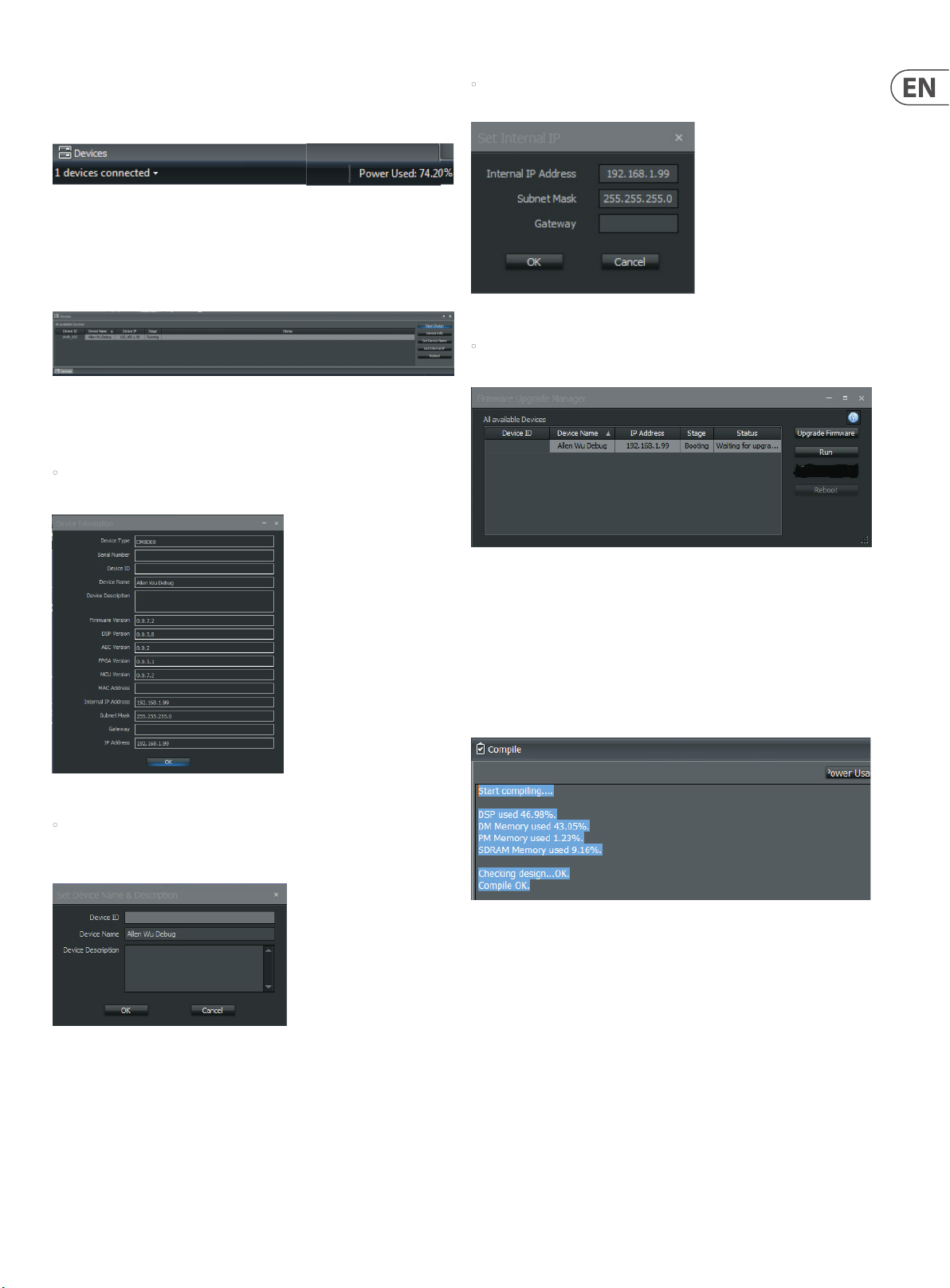
2.1.15 Status Bar
The Status Bar displays connected devices and the amount of available DSP
power in use.
Status Ba r
2.1.16 Device Panel
The Device Panel gives a complete list of devices available via
Ethernet networking.
DM8000 D evices Panel
The Device Panel can be launched from either the View Toolbar (click on the
Device Panel Icon) or from the View Pulldown Menu.
• Device Info button will launch the Device Information Display for quick
reference of each device’s network con guration.
• Set Internal IP button launches a dialog box where you may assign IP
addresses for each device in your network.
Set Inter nal IP Dialog Box
• Reboot button launches the Firmware Upgrade Manager Control Dialog so
you may update rmware for selected devices.
Device Information Display
• Set Device Name button launches the Set Device Name & Description
dialog box so you may assign customized name to each device and write up a
brief description of the device’s role and function in your network.
Firmware Upgrade Manager Dialog Box
2.1.17 Network Panel
The Network Panel shows a map of the entire network system and the flow of
audio through the system.
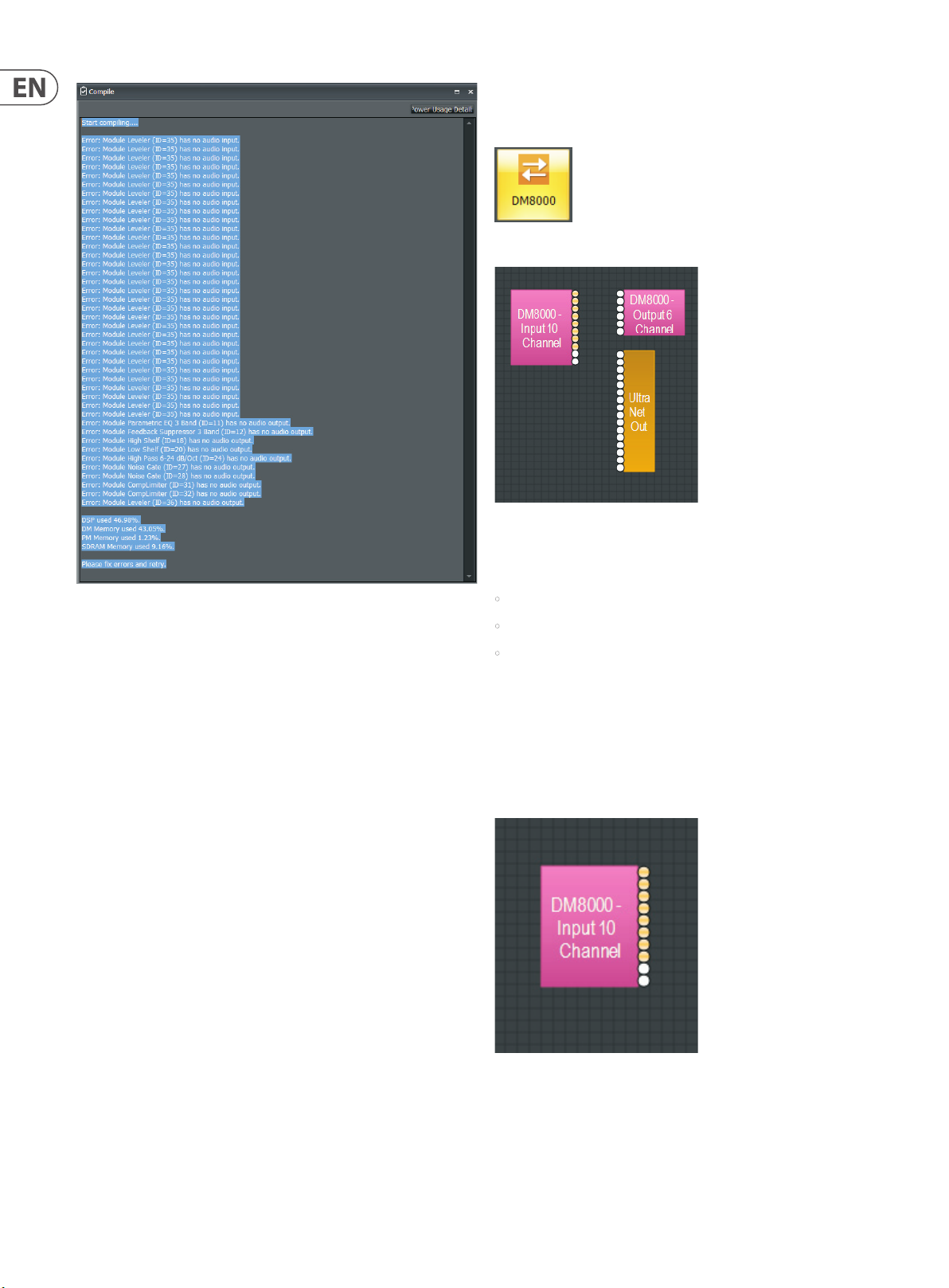
2.1.18 Compile Output Panel
The Compile Output Panel displays the results of the Compile command.
Compile Output Panel
When the Compile process encounters problems with the signal processing
design, the system will open a Compile Output Panel listing the various errors in
the design:
Set Devic e Name & Descripti on Dialog Box
Page 12
12 DM8000 User Manual
3.1.1 DM8000
The DM8000 module is the first module contained in the Input Output
Module Library.
DM8000 M odule Icon
Compile Ou tput Panel with Er rors Displayed
3. Module Library
The DM8000 DSP is equipped with comprehensive library of processing modules
that can be deployed and configured by using the DM8000 DSP Designer
software. You can build the entire processing structure and signal routing using
the DM8000 DSP Designer software, and then compile the configuration and run
it in the DM8000 DSP.
To deploy a specific module, click on that module’s graphic icon in the Module
Library screen, and then drag the module into the Build Window. Alternately, you
can also use the Module Library Toolbar to access all of the DM8000 modules.
Once a module is placed into the Build Window, the module “unzips” and the
Component Objects contained in the Module appear on screen. All available
settings can then be accessed by right-clicking over the desired Component
Object. Right-clicking launches a Control Dialog Box, which displays the
component controls in a more conventional user interface where you can
program settings and make other adjustments.
3.1 Input Output Modules
DM8000 Module Component Objects
Once deployed in the Build Window, the DM8000 module unfolds into three
Component Objects:
• DM8000 Input 10 Channel
• DM8000 Output 6 Channel
• UltraNet Out
These Component Objec ts can be moved and placed separately where needed.
DM8000 Input 10 Channel
The DM8000 Input 10 Channel component object routes analog audio signals
from the 10 analog inputs on the DM8000 rear panel into the DSP for processing.
Analog audio inputs that are equipped with Acoustic Echo Cancellation (AEC)
appear with a light orange color.
To open the Input Output Module Library, click on the Input Output tab in
the lower left of the screen, or use the Module Library Toolbar at the top of
the screen.
DM8000 In put 10 Channel Compone nt Object
Page 13
13 DM8000 User Manual
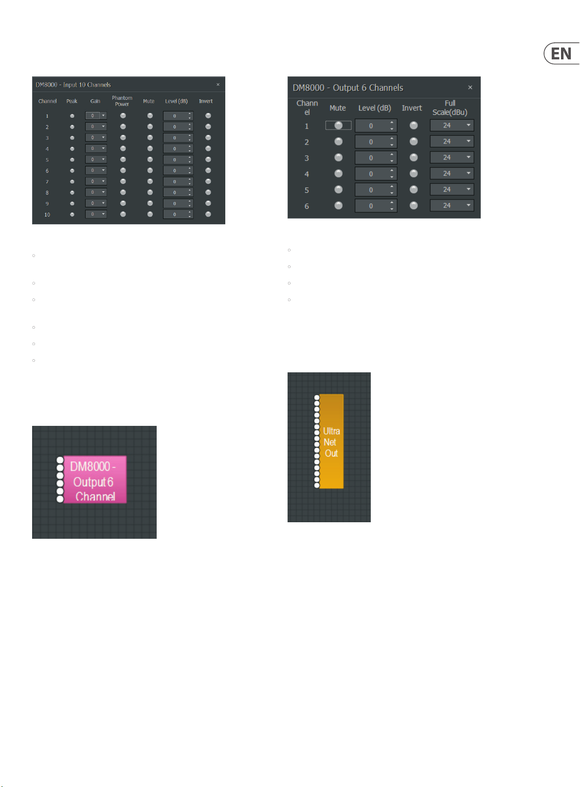
Right-click to access the Component Object’s Dialog Box, with the
following controls:
DM8000 In put 10 Channel Dialog B ox
• Peak ashes only occasionally when a signal exceeds the channel headroom
(6dB headroom).
• Gain compensates for di erent input levels (mic or line).
• Phantom Power assigns +48 Volt phantom power to the input for
condenser microphones.
• Mute switches the input signal on or o .
• Level (dB) adjusts the relative input volume.
• Invert reverses the polarity of the input signal.
Right-click to access the Component Object’s Dialog Box, with the
following controls:
DM8000 O utput 6 Channel Dia log Box
• Mute turns the output signal on or o .
• Level adjusts the relative output volume.
• Invert reverses the polarity of the output signal.
• Full Scale selects the appropriate maximum output reference level
(mic or line).
UltraNet Out
The UltraNet Out Component Object connec ts the DSP processor to the ULTRANET
OUT connection on the rear panel of the DM8000 hardware unit.
DM8000 Output 6 Channel
The DM8000 Output 6 Channel component object routes analog audio signals
out from the DSP to the six analog outputs on the DM8000 rear panel.
DM8000 O utput 6 Channel Com ponent Object
UltraNet Out Component Object
Page 14
14 DM8000 User Manual
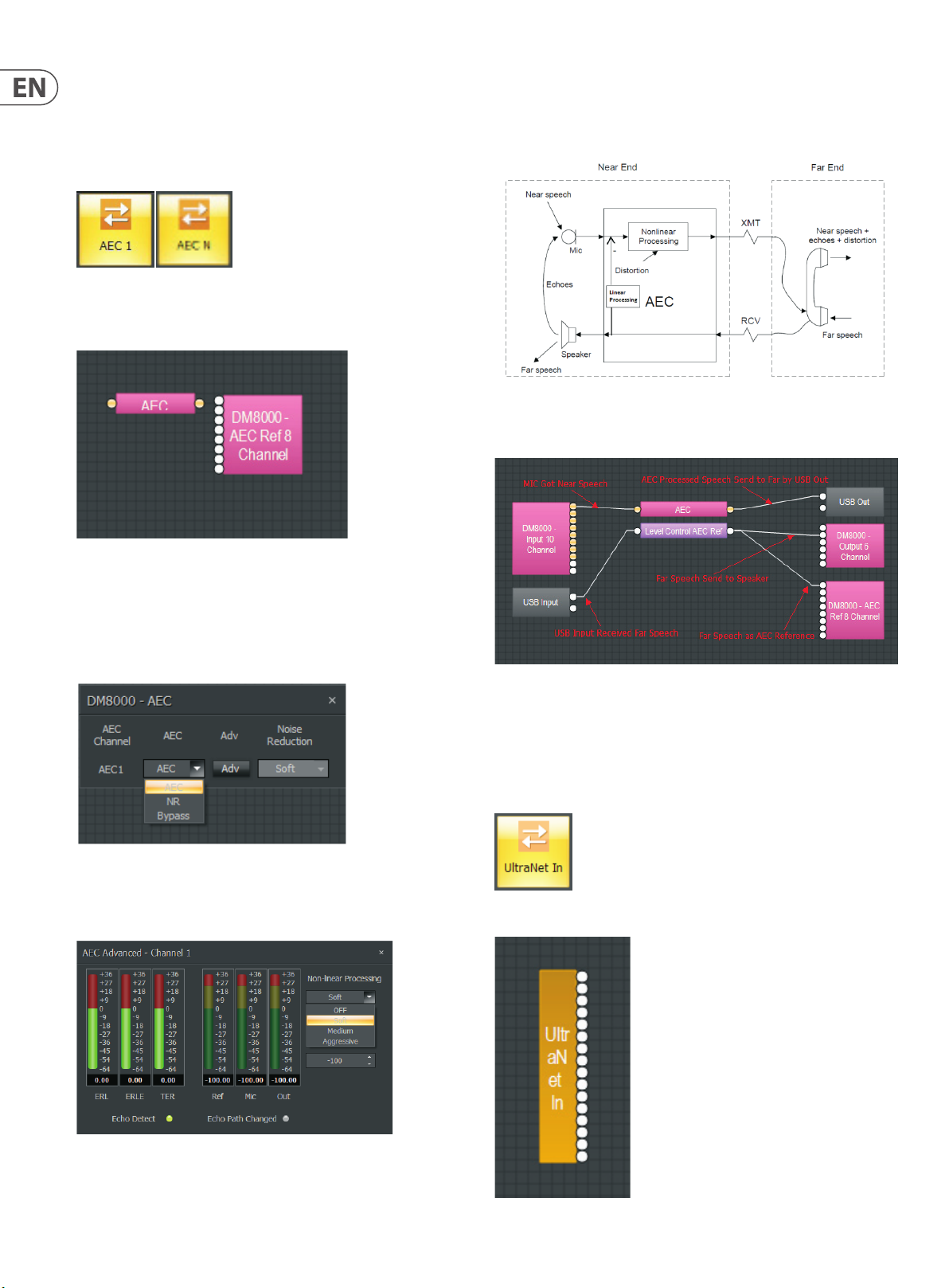
3.1.2 AEC 1 and AEC N Modules
AEC 1 and AEC N modules provide Acoustic Echo Cancellation (AEC). When
designing an AEC processing channel for DM8000, drag in AEC 1 for a single
channel of processing, or drag in AEC N for multiple channels (within theAEC
Nmodule, the user can selectup to 8 AECchannels, numbered 1 through 8).
AEC 1 and AEC N Mod ule Icons
AEC 1 and AEC N Component Objects
Selecting the Adv tab launches an AEC Advanced dialogue window,
where you can select between Non-Linear Processing options (OFF, Soft,
Medium, Aggressive).
The following graphic describes a typical AEC system:
Typical AEC sy stem
For DM8000, a typical AEC design will resemble the following graphic:
AEC 1 and AEC N Comp onent Object s
The AEC Ref 8 Channel sub-module automatically appears when either AEC 1
or AEC N modules are dragged into the Build Window. This module processes a
signal as a reference baseline for the AEC process.
AEC 1 and AEC N Component Object Dialog Boxes
AEC Dialog B ox
The AEC 1 and AEC N control dialogue allows the user to selec t between AEC, NR
and Bypass settings.
Typical AEC de sign in DSP Designer
3.1.3 UltraNet In
UltraNet In module supports MUSIC GROUP’s own proprietary ULTRANET digital
audio format. ULTRANET audio enters DM8000 through the included ULTRANET IN
port on the rear of the DM8000 hardware unit.
UltraNet In module icon
AEC Advance d Dialog Box
UltraNet In Component Object
Page 15
15 DM8000 User Manual
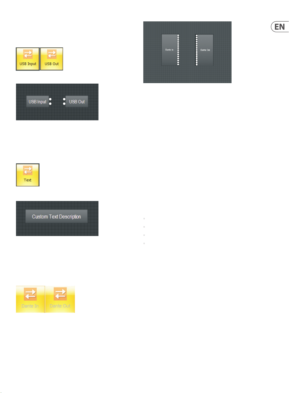
3.1.4 USB Input and USB Out
USB Input and USB Out modules support 2-channel input and output for USB
audio at 24-bit sample size.
USB Input and USB O ut Module Icons
USB Input and USB O ut Component Obje cts
3.1.5 Text
Tex t module allows you to place customized text descriptions wherever needed
in the Build Window. To edit text in the module, press F2 or right-click and
select Edit Text.
Dante In and Dan te Out Component Obj ects
NOTE: When connecting DM8000 devices and Dante cards at the same
time, make sure the IP address of the PC, DM8000 and Dante cards share the
same subnet.
About Dante Digital Networking
Dante is a proprietary digital media net working solution developed by Audinate
and licensed by MUSIC GROUP, which operates on 100 Mbps and Gigabit networks
using standard Internet Protocol (IP) over Ethernet. A Dante stream distributes
both audio and integrated control data over the network. Dante allows for
transport of low-latency, uncompressed audio over standard IP Ethernet
networks with sample-accurate synchronization, automatic device and channel
discovery, and easy –to-use signal routing.
Text Module I con
Text Module Component Object
3.1.6 Dante In/Out
The Dante In and Dante Out modules support Dante digital networking based
on Audinate’s Brooklyn II module. The Dante modules are fixed at 16 input and
16 output channels. These modules can be re-named in the DM8000 DSP
Designer software.
Many of the properties of the Dante streams (or channels) are configurable only
through Audinate’s Dante Controller software. Most impor tantly, routing of
audio signals from transmit to receive between devices is accomplished in Dante
Controller. Once online, routing and channel assignment can only be done in
Dante Controller software.
3.2 Mixers
Mixer modules provide typical audio mixing functions in four categories:
• Standard Mixers
• Matrix Mixers w/Delay
• Matrix Mixers
• Auto Mixers
Mixers are available in pre-defined configurations, however, the configuration
may be customized. Once a Component Object is placed into the Build Window,
all available settings can be accessed by double-clicking over the objec t.
This produces a Control Dialog Box, which displays the component controls in a
more conventional user interface.
To open the Mixers Module Library, click on the Mixers tab in the lower lef t of
the screen, or use the Module Library Toolbar at the top of the screen.
Dante In/Ou t Module Icons
Page 16
16 DM8000 User Manual
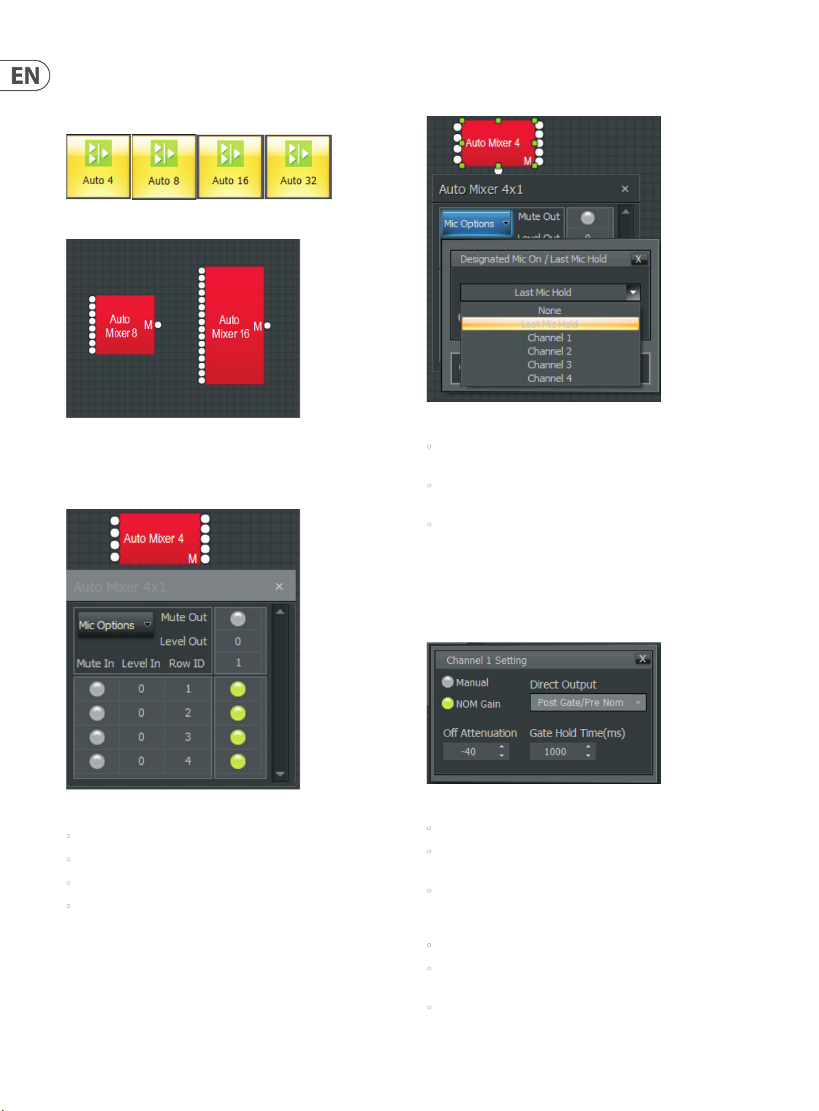
3. 2.1 Auto Mixer
Auto Mixer modules automatically adjust and balance levels for multiple inputs
before sending the combined signal to a single output.
Auto Mixer Mo dule Icons
Auto Mixer Component Objects
Auto Mixer Dialog Boxes
Double-click to open the Control Dialog Box and access the following settings:
Mic Options
Mic Options opens a separate control dialog box to establish global settings:
Auto Mixer Mi c Options Dialog Box
• Designated Mic On / Last Mic Hold determines which microphone (if any)
will stay/become active when no signal is present.
• Logic Outputs Follow Mic Logic assigns logic outputs to follow
Designated Mic On / Last Mic Hold.
Auto Mixer Di alog Box
• Mute In turns the input signal on or o .
• Level In adjusts the relative input volume.
• Mute Out turns the output signal on or o .
• Level Out adjusts the relative output volume.
• Open Mic Limits enables (and designates) a maximum allowable number
of active microphones.
Channel Settings
Channel Settings can be accessed by right-clicking overthe Row IDassignment
nodes. Channel Settingsaffects individual channel settings, but may also be
applied globally to all channels within the Auto Mixer module.
Channel Settings Dialog Box
• Manual turns channel gating on or o .
• NOM Gain activates/deactivates the channel contribution to NOM
(number of open mics) attenuation.
• Direct Output designates channel direct output signal as Post Gate /
Pre NOM or Post Gate / Post NOM. (Direc t Outputs must be enabled when
placing Auto Mixers from the Module Library Toolbar.)
• Set All causes current Channel Settings to be applied to all channels.
• O Attenuation determines the amount of attenuation applied when the
channel is inactive.
• Gate Hold Time determines length of time before the channel becomes
inactive once signal is no longer present.
Page 17
17 DM800 0 User Manual
Logic Outputs
Logic Outputs affects individual Logic Output settings, but may be applied to all
Logic Outputs. (Logic Outputs must be activated when placing Auto Mixers from
the Module Library Toolbar).
Logic Out puts Dialog Box
• Logic Output selects Follow Gate, On or O condition of the Logic Output.
• Invert reverses operation of the Logic Output (o when channel active).
• Set All causes current Logic Output settings to be applied to all channels.
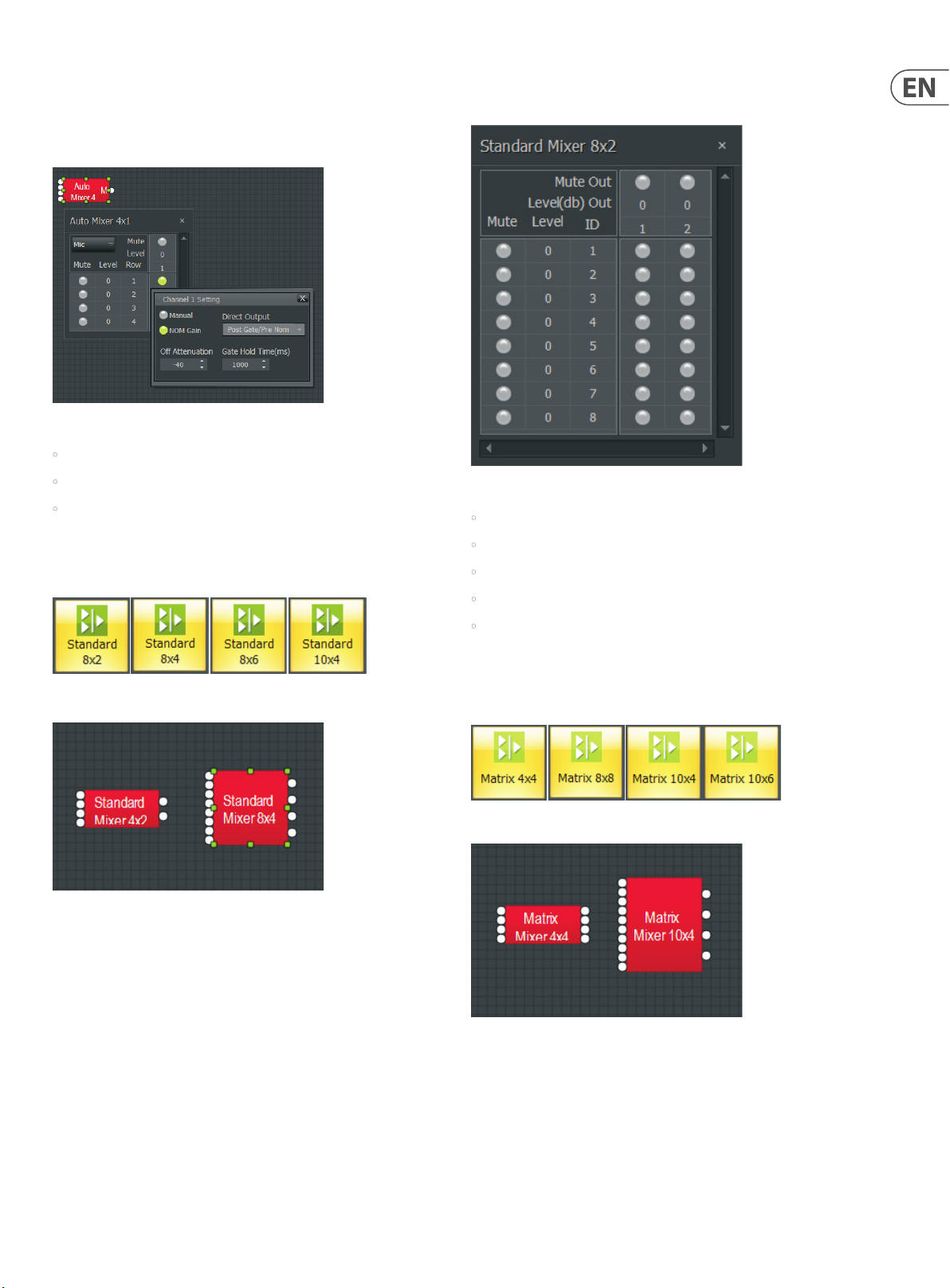
3.2.2 Standard Mixer
Right-click to access the Component Object’s Dialog Box, with the
following controls:
Standard Mi xer Dialog Box
• Mute In turns the input signal on or o .
• Level In adjusts the relative input volume.
Standard Mixer modules offer controls most similar to regular analog mixers.
Standard Mixer Module Icons
Standard Mixer Component Objects
• ID assigns inputs to speci c outputs.
• Mute Out turns the output signal on or o .
• Level Out adjusts the relative output volume. Right-clicking over certain
settings will provide a menu of additional options
3.2.3 Matrix Mixer
Matrix Mixer modules offer extended bus routing options.
Matrix Mixer Module Icons
Matrix Mixer Component Objects
Page 18
18 DM8000 User Manual
Right-click to access the Component Object’s Dialog Box, with the
following controls:
Matrix Mi xer Dialog Box
• Mute In turns the input signal on or o .
• Level In adjusts the relative input volume. Left-click to adjust levels.
• Assign Matrix assigns inputs to speci c outputs.
• Mute Out turns the output signal on or o .
• Level Out adjusts the relative output volume.
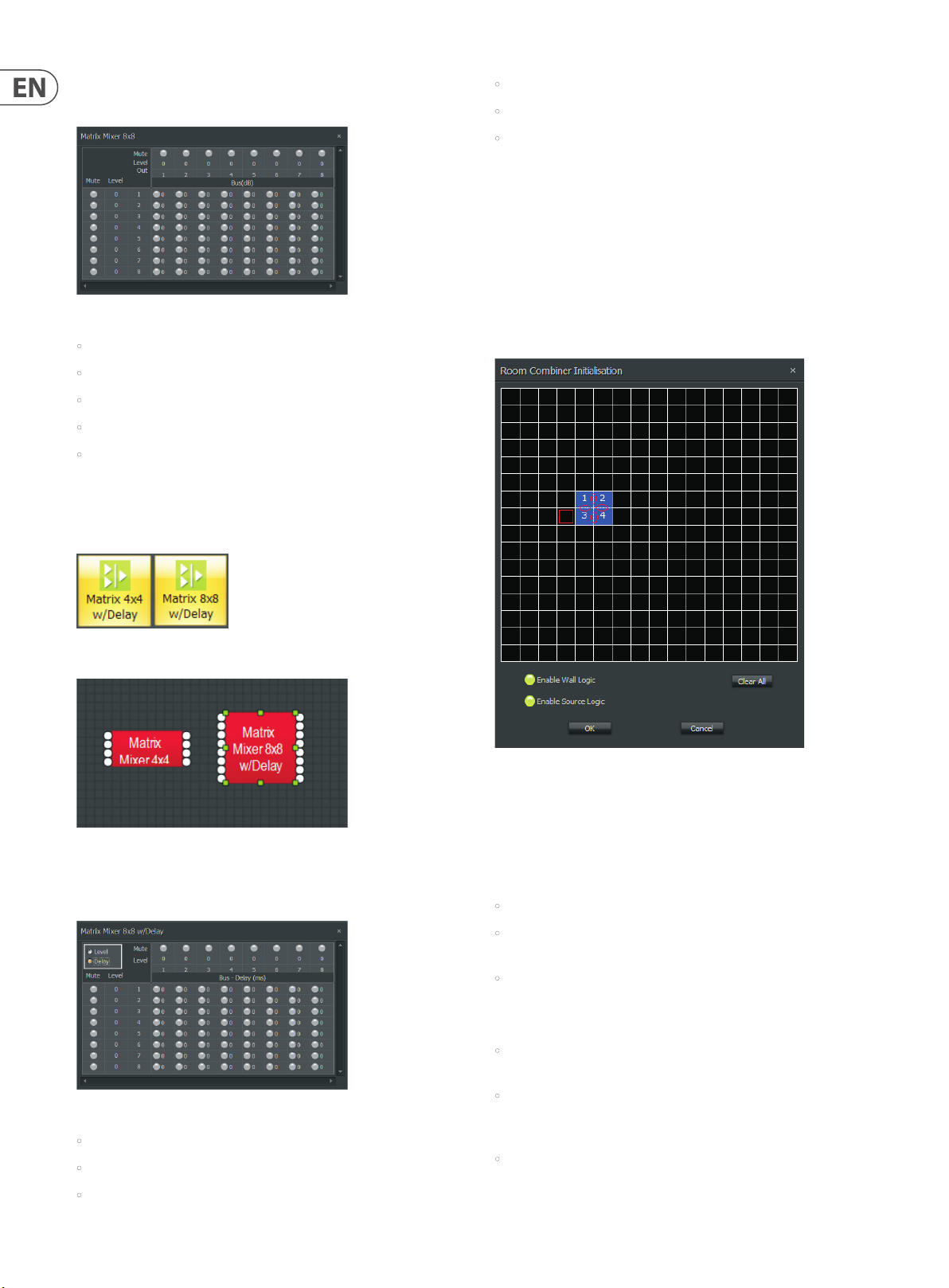
3.2.4 Matrix w/Delay
Matrix w/Delay adds a delay feature but otherwise functions like the
Matrix Mixer.
• Mute Out turns the output signal on or o .
• Level Out adjusts the relative output volume. Left-click to adjust levels.
• Delay adjustment is same as level adjustment.
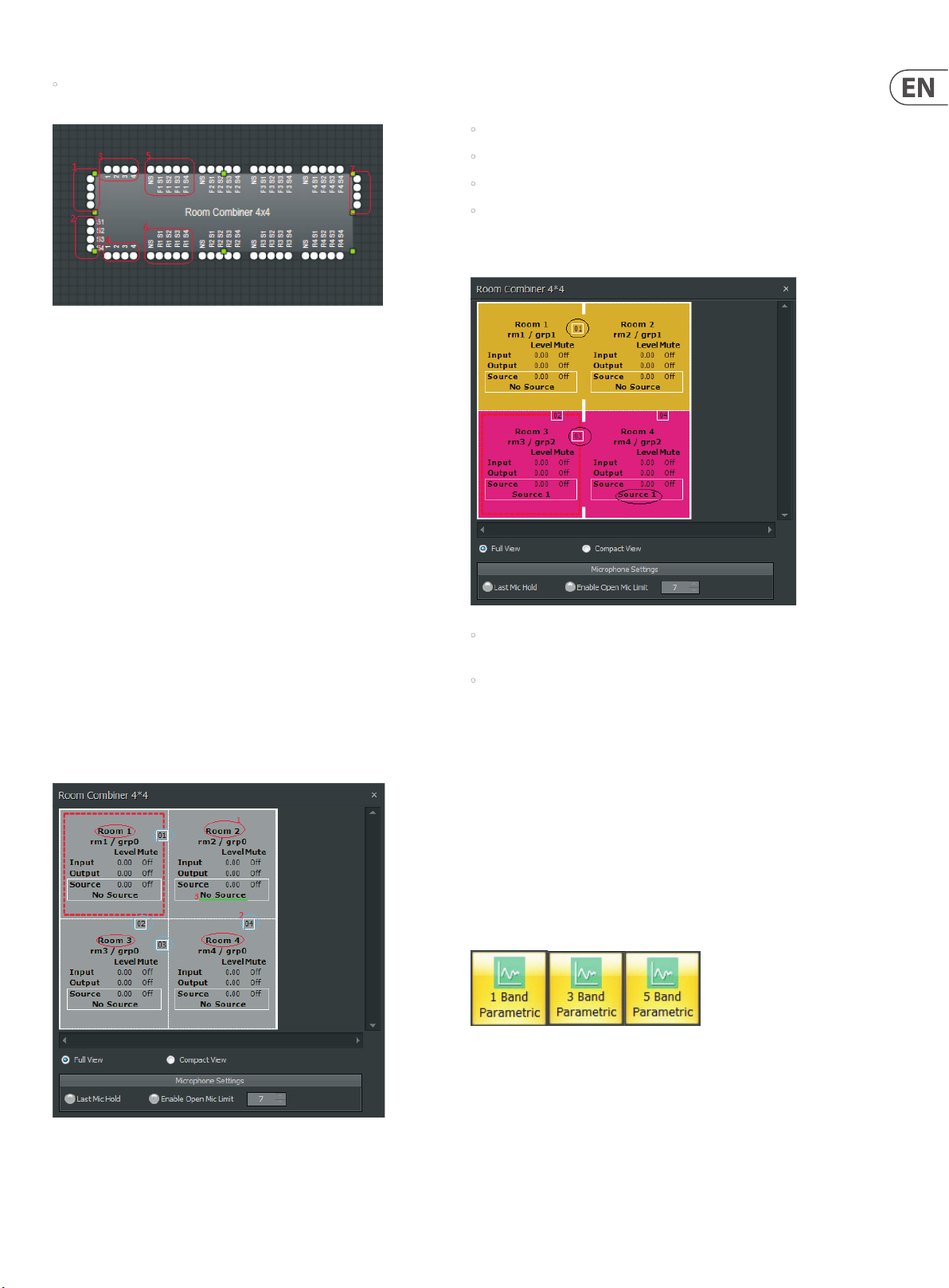
3.2.5 Room Combiner
The Room Combiner module acts as a router that can manage audio streams
routing and control of combinable/divisible spaces. This module can support
a maximum of 16 rooms in numerous configurations, with combinable levels,
muting and source tracking. Logic inputs and outputs are provided for wall state
and source selection, as well as the ability to combine and control the func tion of
Auto Mixer modules connected to the Room Combiner module’s inputs.
When a Room Combiner module is dropped into the Build Window, the software
will automatically launch a Parameter Dialog Box:
Matrix w/D elay Module Icons
Matrix w/Delay Component Objects
Right-click to access the Component Object’s Dialog Box, with the
following controls:
Matrix w/D elay Dialog Box
• Mute In turns the input signal on or o .
• Level In adjusts the relative input volume. Left-click to adjust levels.
• Assign Matrix assigns inputs to speci c outputs.
Room Combiner Initialisation Dialog Box
In the Dialog Box, Room Combiner uses a 16x16 grid of blocks to lay out
graphically the relative position of each room. Adjacent, enabled blocks in
the grid can have three types of walls: permanent, removable and none.
The wall type is selected by repeatedly clicking on the border between adjacent
enabled blocks.
• Clear All button removes all blocks from the grid.
• Enable Wall Logic controls whether the Room Combiner Component Object
will have logic connections for wall state.
• Enable Source Logic determines whether logic connections for source
selection will appear on the Component Object.
Please keep in mind the following points:
• Removable walls are indicated by a thin dashed line, and the removable wall
will have a corresponding logic node on the block.
• Permanent walls are indicated by a thick gray line that represents a non-
removable border between those rooms. A permanent wall will not have a
logic connection on the block.
• No border between adjacent enabled blocks indicates there is no wall, and
the adjacent enabled blocks are therefore considered part of the same space.
Page 19
19 DM8000 User Manual
• Rooms that are combinable via a removable wall will share at least
one border.
Room Combiner Component Object
The Room Combiner Component Object can display the following types of input
and output terminals (refer to the numbered items in the screenshot above):
1. Standard input terminals. Each room has one input
2. Auxiliary audio input terminals. Each room hasone auxiliary input, and
each room can selec t any one of these auxiliary audio inputs.
3. Logic Input terminals. Each wall has one logic input terminal. When the
logic input receives a signal from HIGH-to-LOW,the relative wall is removed.
When the logic input received signal from LOW-to-HIGH, the relative wall
is placed.
This Dialog Box offers the following labels and functions (refer to the
above screenshot):
• Room Name can be edited as in #1 in the above screenshot.
• Wall ID is visible as in #2 in the above screenshot.
• Auxiliary Audio selection is displayed as in #3 above.
• Last Mic Hold and Open Mic Limits are connected with Auto Mixer.
The Room Combiner Dialog Box also shows information about combined rooms
and walls:
4. Logic Output terminal. Each wall has one logic output. When a wall is
placed (by logic input or by manual set), the related logic output will be
HIGH. When a wall is removed, the related logic output will be LOW.
5. Logic Input for Auxiliary Audio Input selection, which can be used to
determine auxiliary audio input.
6. Logic Output of Auxiliary Audio Input, which is determined by auxiliary
audio input selection.
7. Standard output terminals. Each room has one output.
Double-clicking the Room Combiner Component Object produces the following
Control Dialog Box:
• Room 1 and Room 2 have been combinedintoGroup 1 (shown as “grp1”,
please see the gold group). Wall 01 has been opened to combine the rooms.
• Room 3 and Room 4 have been combined intoGroup 2 (shown as “grp2”,
please see the hot pink group).Wall 03 has been opened to combine
the rooms.
3.3 Equalisers
Equaliser modules provide both graphic and parametric equalisation, as well as
feedback suppression. Equalisers may be connected between any components
within the Build Window, for applications which require room equalization,
tone adjustment, or feedback control. Equalisers appear in pre-defined
configurations, but these configurations may be customized when placing
modules from the Module Library Toolbar.
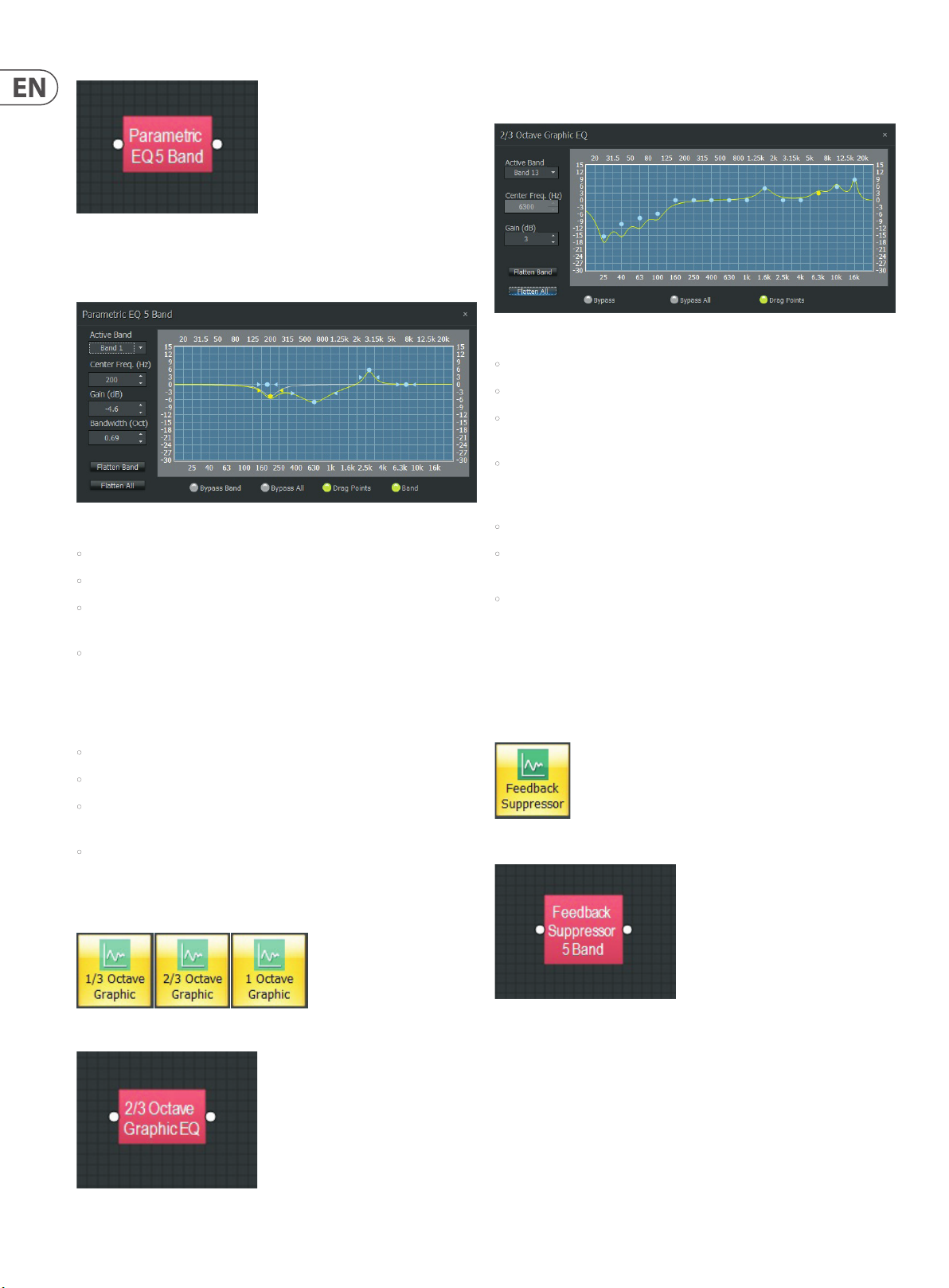
3.3.1 Parametric Equaliser
Parametric Equaliser offers standard parametric functionality.
Room Combi ner Control Dialog B ox
Parametric Equaliser Module Icons
Page 20
20 DM8000 User Manual
Parametric Equaliser Component Object
Right-click to access the Component Object’s Dialog Box, with the
following controls:
Parametric Equaliser Dialog Box
Right-click to access the Component Object’s Dialog Box, with the
following controls:
Graphic Equaliser Dialog Box
• Active Band selects the current frequency band to be adjusted.
• Center Freq. displays the center frequency for the current band.
• Gain adjusts the amount of cut or boost applied at the center frequency for
the current band.
• Active Band and Gain may also be adjusted by dragging the band controls
shown inside the graph. The selected band control becomes yellow, and
dragging it up or down aects Gain for that band.
• Flatten Band and Flatten All changes the band Gain to “0” (at).
• Active Band selects the frequency band to be adjusted.
• Center Freq. adjusts the center frequency for the current band.
• Gain adjusts the amount of cut or boost applied at the center frequency for
the current band.
• Bandwidth adjusts the range of frequencies, above and below the center
frequency, which are also aected by the current band. These settings may
also be adjusted by dragging the band controls shown inside the graph.
Dragging the white dot aects both Center Freq and Gain. Dragging either
yellow dot aects Bandwidth.
• Flatten Band and Flatten All changes the band Gain to “0” (at).
• Bypass Band and Bypass All disables bands without changing settings.
• Drag Points turns the band controls on or o, revealing the
resultant curve only.
• Band highlights the current band inside the graph.
3.3.2 Graphic Equaliser
Graphic Equaliser adjusts frequencies in set frequency bands.
Graphic Equaliser Module Icons
• Bypass Band and Bypass All disable the band(s) without
changing settings.
• Drag Points turns the band controls on or o, revealing the resultant
curve only.
3.3.3 Feedback Suppressor
Feedback Suppressor behaves like automatic cut-only Parametric Equaliser
module. Parametric equalisers utilize automatically-assignable bands of
equalization which detect and remove feedback frequencies.
Feedback Suppressor Module Icon
Feedback Suppressor Component Object
Graphic Equaliser Component Object
Page 21

21 DM8000 User Manual
Right-click to access the Component Object’s Dialog Box, with the
following controls:
Feedback Suppressor Dialog Box
• Active Band selects the current band for which settings will be displayed.
• Center Freq. displays the center frequency for the current band.
• Gain displays the amount of cut applied at the center frequency for the
current band.
• Bandwidth displays the range of frequencies, above and below the center
frequency, which are also aected by the current band. Float Limits restricts
all oating bands to a selec ted maximum depth (cut) and bandwidth
(Narrow = 1/40-octave; Wide = 1/10-octave).
• Reset All temporarily returns the gain of all oating bands to 0dB (at).
• Fix Band and Fix All frees frequency bands to become manually adjustable
(non -oating).
High Pass Component Object
Right-click to access the Component Object’s Dialog Box, with the trols:
High Pass Di alog Box
• Filter Slope selects the lter type (Linkwitz-Riley or Butterworth) and slope
of the lter.
• Cuto Freq. selects the cuto frequency for the lter. Cuto Freq. may also
be adjusted by dragging the cursor shown inside the graph.
• Bypass turns the lter on or o.
• Bypass Band and Bypass All disable frequency band without
changing settings.
• Drag Points turns the band controls on or o, revealing the resultant curve
only. Band highlights the current band inside the graph.
NOTE: Feedback Suppressor modules use a hefty amount of processing power
and are limited to a maximum of six teen bands, although, in practice the number
of bands actually in use will often be fewer. The Feedback Suppressor’s active
bands can also be recreated within a Parametric Equalizer to save DSP resources.
3.4 Filters
Filter modules provide High Pass, Low Pass, High Shelf, Low Shelf and AllPass filters for applications that require rolling off of frequencies, simple tone
controls, or phase compensation.
Filters may be connected between any components within the Build Window.
3. 4.1 High Pass
High Pass Module Icons
3.4.2 Low Pass
Low Pass Mod ule Icons
Low Pass Component Object
Page 22

22 DM8000 User Manual
Right-click to access the Component Object’s Dialog Box, with the
following controls:
Low Pass Dial og Box
• Filter/Slope selects the lter type (Linkwitz-Riley or Butterworth) and
slope of the lter.
• Cuto Freq. selects the cuto frequency for the lter. Cuto Freq. may also
be adjusted by dragging the cursor shown inside the graph.
• Bypass turns the lter on or o.
3.4.3 High Shelf
3.4.4 Low Shelf
Low Shelf Mo dule Icon
Low Shelf Component Object
Right-click to access the Component Object’s Dialog Box, with the
following controls:
High Shelf M odule Icon
High Shelf Component Object
Right-click to access the Component Object’s Dialog Box, with the
following controls:
High Shelf D ialog Box
Low Shelf Dia log Box
• Gain selects the amount of maximum cut or boost applied by the lter.
• Cuto Freq. selects the cuto frequency for the lter. These settings may
also be adjusted by dragging the cursor shown inside the graph.
• Bypass disables the lter without changing settings.
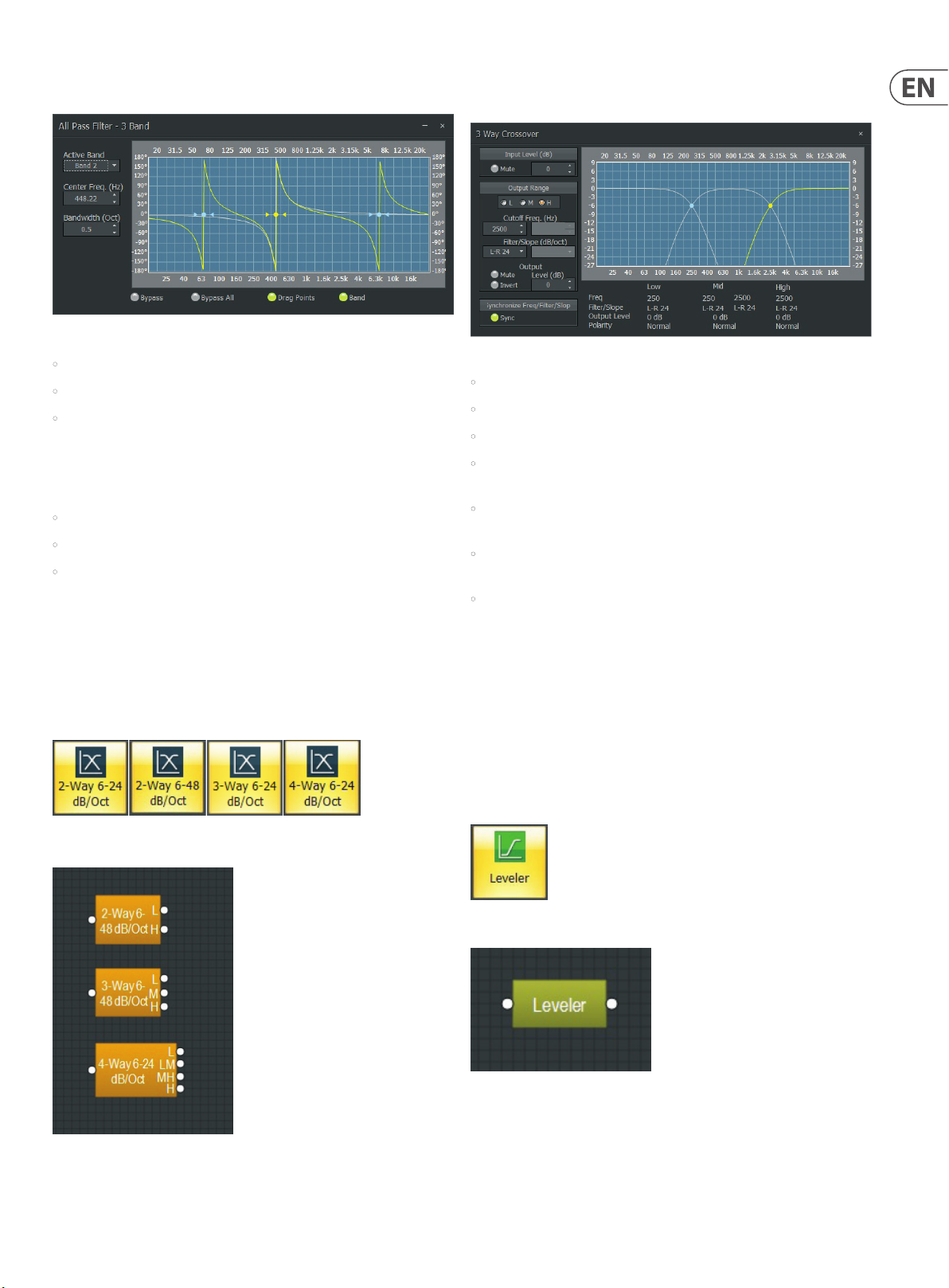
3.4.5 All Pass
All Pass filters affect signal phase instead of frequenc y response, and All Pass
modules can be used to compensate for phase problems sometimes caused by
normal equalization f ilters. All-Pass Filters are available with up to sixteen bands.
All Pass Mod ule Icons
• Gain selects the amount of maximum cut or boost applied by the lter.
• Cuto Freq. selects the cuto frequency for the lter. These settings may
also be adjusted by dragging the cursor shown inside the graph.
• Bypass turns the lter on or o.
All Pass Component Object
Page 23
23 DM8000 User Manual
Right-click to access the Component Object’s Dialog Box, with the
following controls:
All Pass Dial og Box
• Active Band selects the current band to be adjusted.
• Center Freq. adjusts the center frequency for the current band.
• Bandwidth adjusts the range of frequencies, above and below the center
frequency, which are also aected by the current band. These settings may
also be adjusted by dragging the band controls shown inside the graph
(the drag points turn yellow when selected). Dragging the yellow dot aects
Center Freq. Dragging either yellow arrowhead aects Bandwidth.
• Bypass and Bypass All disables the bands without changing settings.
• Drag Points turns on/o the band controls.
• Band shows the phase response of the current band inside the graph.
Right-click to access the Component Object’s Dialog Box, with the
following controls:
3-Way Crossover Dialog Box
• Input Level provides muting and level adjustment for the input.
• Output Range selects the Low, Middle or High frequenc y output.
• Cuto Frequency selects the lter cuto frequency for the selected output.
• Output Range and Frequency may also be selected by dragging the
cursors shown inside the graph.
• Filter/Slope selects the type (Linkwitz-Riley or Butterworth) and slope of
lter used at the associated Frequency.
• Output Level provides level adjustment, muting and polarity reversal for
the selected output.
3.5 CrossOvers
Crossovers provide 2-way, 3-way and 4-way crossover functions.
Crossovers may be connected between any components within the Build
Window, for applications which require multiple outputs with specified
frequency ranges.
3. 5.1 2-Way/3-Way/4-Way Modules
2-Way, 3-Way and 4-Way Crossove r Module Icons
• Sync forces lter adjustments on adjacent outputs to be linked.
Complete settings for each output appear across the bottom of the dialog box.
3.6 Dynamics
Dynamics modules provide Leveler, CompLimiter, Ducker, Noise Gate,
and ANC (Ambient Noise Compensator) functions. Dynamics modules may
be connected between any other components within the Build Window, for
applications which require automatic control of volume levels and/or dynamics.
3. 6 .1 Leveler
Leveler automatically controls gain to even out long-term average levels.
Leveler Module Icon
2-Way, 3-Way and 4-Way Crossove r Component Objec ts
Level Component Object
Page 24

24 DM8000 User Manual
Right-click to access the Component Object’s Dialog Box, with the
following controls:
Leveler Dialog Box
• Response Time determines how quickly the Leveler reacts to changes in
the input level.
• Threshold determines the minimum input level that will trigger gain
reduction. To maintain a consistent level, set Threshold to the lowest desired
level. A meter and numeric display show the amount of gain reduction when
the input signal exceeds the threshold.
• Bypass deactivates the Leveler and sends the signal straight through
without processing. Settings remain the same while bypassed.
Right-click to access the Component Object’s Dialog Box, with the
following controls:
CompLimiter Dialog Box
• Attack Time controls how quickly the Comp/Limiter responds to input
level changes.
• Ratio determines the intensity of gain reduction (input level increase vs.
output level increase).
• Release Time determines how quickly gain reduction is released,
once input signal falls below Threshold.
• Threshold determines what input level will trigger gain reduction. A meter
and numeric display indicate the amount of gain reduction.
• Bypass deactivates the Comp/Limiter and sends the signal straight through
without processing. Settings remain the same while bypassed.
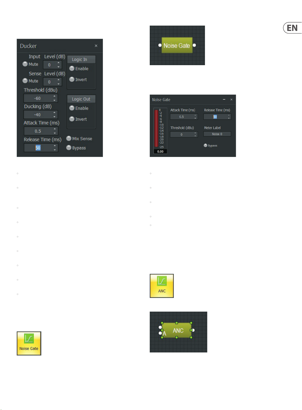
3.6.3 Ducker
Ducker attenuates the input level when triggered by an additional signal or
logic input.
3.6.2 CompLimiter
CompLimiter modules even out short-term dynamic peaks in the input signal.
CompLimiter Module Icon
CompLimiter Component Object
Ducker Module Icon
Ducker Component Object
Page 25
25 DM8000 User Manual
Right-click to access the Component Object’s Dialog Box, with the
following controls:
Noise Gate Component Object
Right-click to access the Component Object’s Dialog Box, with the
following controls:
Ducker Dialog Box
• Input Level provides muting and level adjustment for the primary audio
input (the upper input terminal on the left side of the Ducker).
• Sense Level provides muting and level adjustment for the secondary
“trigger” signal input (the lower input terminal marked “S” on the lef t side
of the Ducker).
• Threshold controls the level at which the secondary audio signal will
trigger ducking.
• Ducking Level controls how much attenuation is applied to the primary
audio signal during ducking.
• Attack Time determines how quickly the ducker responds to the secondary
audio or logic “trigger” signal.
• Release Time controls how quickly the ducker eect lets go of the primary
audio signal.
• Logic In turns the logic input on/o and can invert the logic signal,
if necessary.
• Logic Out allows the ducker to send out its own logic signal to
another device.
• Mix Sense enables the ducker to detect a “trigger” signal within a mix of
multiple audio signals.
Noise Gate D ialog Box
• Attack Time controls how quickly the gate opens when a signal is present
at the input.
• Release Time controls how quickly the gate closes when a signal is no
longer present.
• Threshold sets the input signal level that will trigger the gate to open.
A meter and numeric display indicate the amount of gain reduction.
• Meter Label lets you name and identify the source of the input signal.
• Bypass switches the Noise Gate on or o.
3.6.5 ANC (Ambient Noise Compensator)
3. 6 . 5.1 ANC Module (Ambient Noise Compensator)
ANC (Ambient Noise Compensator) automatically adjusts volume when
triggered by changes in background noise levels, as measured by an external
ambient sensing microphone.
ANC Module I con
3.6.4 Noise Gate
Noise Gate provides automatic muting, until the gate is triggered and opened
by an incoming audio signal.
Noise Gate M odule Icon
ANC Component Object
Page 26

26 DM8000 User Manual
Right-click to access the Component Object’s Dialog Box, with the
following controls:
ANC Dialog B ox
NOTE: The primary signal is referred to as the “Program” signal, while the
secondary reference signal is referred to as the “Ambient” signal.
• Program Mute turns the input signal on or o.
• Program Level adjusts the relative input volume.
• Program Label provides a customizable label for the source of the primary
Program input signal.
• Prog Meter displays the current input level.
• Ambient Mute turns the ambient input signal on/o.
• Ambient Level adjusts the input volume for the Ambient input.
• Ambient Threshold sets the Ambient noise level at which gain increases
are applied to the Program signal.
• Ambient Response sets the time period during which the ANC module
calculates the working average of Ambient level uctuations.
• Ambient Label provides a customizable label for the Ambient
signal source.
• Amb Meter displays the current Ambient input level.
• Gain Min determines the minimum Program output gain for periods of low
ambient noise.
3. Connect the ANC Component Object’s output terminal to the input terminal
of the nal Output Component Object in the signal path (DM8000 Output
6 Channel, UltraNet Out, or USB Out).. ANC should be the last Component
Object in the signal path before routing the signal to outputs. For consistent
performance once levels have been set, do not subsequently adjust the level
settings at the outputs, ampliers, or speakers.
3.6.5.3 Setting Gain Min and Gain Max
For best results, you should set Program gain levels by using a relatively constant
Program source signal. If the actual source Program signal is not constant
enough, pink noise can also be used to set levels (provided the pink noise
approximates the highest Program level that you expect will be routed into the
ANC module).
1. Adjust the Gain Min and Gain Max levels to your desired settings for the
Program signal. Note that the Gain Min setting represents the minimum
constant gain that the ANC module will apply to the Program input signal
when the Ambient signal level drops below the Ambient Threshold.
Similarly, the Max Gain setting represents the maximum amount of gain that
you expect the ANC module will ever apply to the Program input level.
2. If Gain Min and Gain Max are not known in advance, you may determine
these settings by monitoring the ANC output using this procedure:
a. Set the Ambient Threshold to the maximum setting (+24 dBu)
to make sure the Ambient Input level is below threshold. This maximum
Ambient Threshold setting automatically adjusts the ANC module to
the Min Gain setting. Remember that the Gain Time setting controls
how quickly the ANC module moves the Ambient signal to the
Min Gain setting.
b. Adjust Gain Min until you nd the desired maximum output level.
c. Set Gain Max to the output value you have just discovered using
Gain Min.
d. Re-set Gain Min to the value determined in Step 2a.
e. Adjust Gain Min until you have the desired minimum Program level
coming out of the ANC module. Note this Gain Min setting for later use.
• Gain Max determines the maximum Program output gain for periods of
high ambient noise.
• Gain Ratio determines how much the Program volume will increase in
response to a given noise increase in the Ambient reference signal.
• Gain Time determines the amount of time required for the Program gain to
change between Min and Max settings.
• Gain Meter displays the current gain compensation being applied to the
Program signal.
• Bypass switches o the Ambient Noise Compensator.
3.6.5.2 Making Connections
1. Route the Program signal into the Program Input terminal (top left) on the
ANC Component Object and set the input gain (see “Setting Gain Min and
Gain Max” below).
2. Route the Ambient signal into the Ambient Input (bottom left, marked
with an “A”) on the ANC Component Object. This Ambient signal should be
derived from either a single dedicated sensing microphone, or from an array
of sensing microphones feeding a common Mixer module. For best results,
the ANC Ambient levels should be set when the ambient noise in the room is
minimized and the Amb Meter reads at least -60 dBu.
3.6.5.4 Setting Response Times
1. Adjust Gain Time to gure out how quickly the ANC gain is changing. Gain
Time determines how quickly the ANC module moves from Gain Min to
Gain Max, or vice versa.
2. Adjust the Ambient Response setting to discover how quickly the ANC
module responds to changes in the Ambient input level. Ambient Response
should be set fast enough to respond to signicant and sustained changes
in the Ambient signal level, but slow enough to disregard short, transient
changes in the Ambient signal level, such as coughs, bumps, popping sounds
or dropped objects.
NOTE: The ANC module’s overall responsiveness is controlled by either the Gain
Time setting or Ambient Response setting, whichever is larger/slower.
Page 27

27 DM8000 User Manual
3.7 Routers
Router modules offer audio routing and switching functions from simple source
selection and signal-splitting to complicated input/output matrices. Routers may
be placed between any other components to control signal flows.
3.7.1 In/Out Routers
In/Out Routers let you route multiple input signals to multiple output terminals
by using an assignable matrix. In/Out Routers can duplicate input signals in a way
similar to a splitter or distribution amplifier.
In/Out Rou ter Module Icons
3.7. 2 Source Selection
Source Selection modules allow you to route multiple audio inputs sent to a
single output. Only one source input at a time can be active.
Right-click to access the Component Object’s Dialog Box, with the
following controls:
Source Selection Dialog Box
• Level controls the input gain.
In/Out Router Component Objects
NOTE: In/Out Router inputs can each be individually assigned to multiple
outputs, but each individual output can only accept a single input signal.
Right-click to access the Component Object’s Dialog Box, with the
following controls:
• Source nodes, when clicked, activate their matching input source and light
green. Only one source input can be active at any time.
• Label allows you to create a custom label for each input.
To enable logic inputs and outputs, right-click over the Component Object,
select Parameters from the pop-up menu to launch a dialog box with the
following controls:
Source Selection Parameters Dialog
• Enable Logic activates the logic inputs and outputs. Logic input/output
terminals will then appear on the top and bottom of the Component Object.
• Source Channel Count pulldown menu lets you alter the number of inputs
after you have placed the Source Selection model in the build window.
In/Out Rou ter Dialog Box
• In channels appear as a column on the left side of the routing matrix.
• Out channels appear in a row along the top of the routing matrix.
• To assign an input signal to an output, click on the matrix node located
where the In row intersects with the Out column. When selected, the matrix
node lights green.
Page 28
28 DM8000 User Manual
3.8 Delays
Delay modules provide audio time delay functions for applications such as time
alignment of loudspeakers over distance.
Delay Module Icons
Delay Component Object
Delay modules may be placed between any components within the
Build Window.
Right-click to access the Component Object’s Dialog Box, with the
following controls:
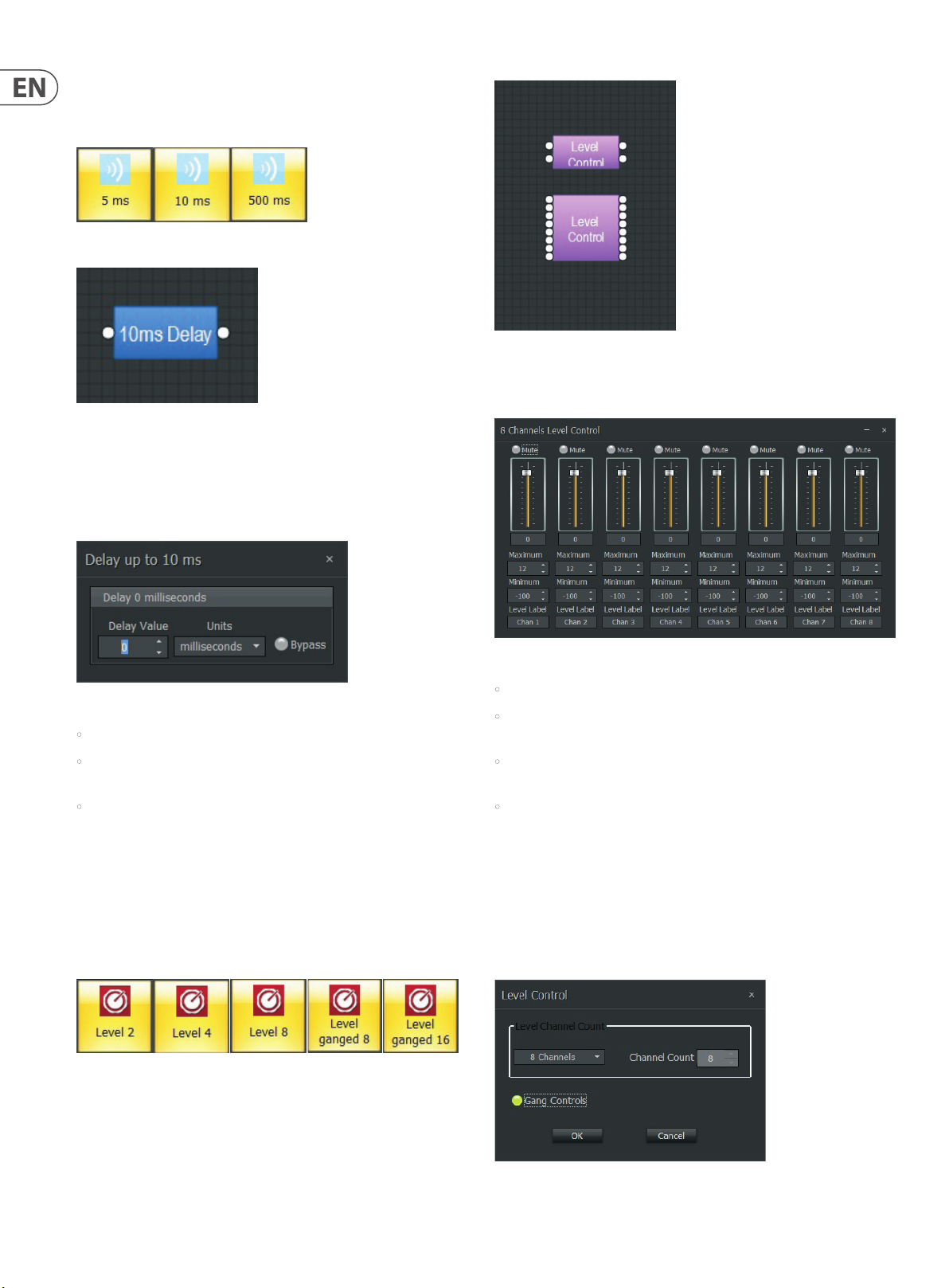
Level Control Component Objects
Right-click to access the Component Object’s Dialog Box, with the
following controls:
Delay Dialo g Box
• Delay Value sets the amount of time delay.
• Units selects the type of unit used by Delay Value, either time (milliseconds)
or distance (meters, centimeters, feet, or inches).
• Bypass switches the Delay module on or o.
3.9 Controls
Controls modules offer more detailed channel strip functions than the Router
and Source Selection modules. These functions include more flexible level
control, phase inversion, muting, logic-controlled switching and “ganging” of
multiple inputs to a single fader.
3. 9.1 Level Control
Level Control Module Icons
Level Control Dialog Box
• Mute turns individual channels on or o.
• Channel level controls may be manually adjusted by dragging the fader,
or the level value may be entered in as a numerical value.
• Maximum and Minimum level values can be used to restrict a channel
fader’s range of level adjustment.
• Level Label lets you create a custom label for channel.
Channel level controls can also be grouped or “ganged” onto a single fader.
Ganged Level Control modules are available in the Module Library, but
regular Level Control modules can also be ganged after being placed in the
Build Window.
To activate ganging in an already-placed Level Control module, right-click over
the Level Control Component Object in the Build Window, and then choose
Parameters from the pop-up menu to access the Gang Controls setting:
Level Contr ol Parameters Dia log Box with Gang Cont rols selecte d
Page 29

29 DM8000 User Manual
Gang Controls button will light green when ac tivated, and the Component
Object in the Build Window will display a “G”:
Ganged Leve l Control Compone nt Object with “G”
The Level Control Dialog Box, when opened, will subsequently show a single
channel strip for all of the ganged inputs:
Right-click to access the Component Object’s Dialog Box, with the
following controls:
Level Inc/Dec Dialog Box
• Mute turns individual channels on or o.
• Channel Level Controls may be manually adjusted by dragging the fader,
or the level value may be entered in as a numerical value.
Level Contr ol Dialog Boxed wit h Ganged Channel Cont rols
3.9.2 Level Inc/Dec
Level Inc/Dec modules provide Logic control terminals for incremental level
changes, but are otherwise identical to Level Control modules.
Level Inc/Dec Module Icons
• Maximum and Minimum level values can be used to restrict a channel
fader’s range of level adjustment.
• Inc/Dec controls the amount of level change that happens each time the
respective logic control terminal is triggered. Logic input terminals along
the top of the Component Objec ts display positive (+) and negative (-)
labels. Signals from the positive (+) logic terminals increase the level by the
programmed Inc/Dec value. Similarly, signals from the negative (-) logic
terminals decrease the level by the same Inc/Dec value.
• Level Label lets you add a custom label to each channel.
Similar to the Level Control Modules, multiple channel controls can be “ganged”
together onto a single fader. Ramping can also be enabled.
Level Inc/Dec modules with ganging and ramping pre-enabled are available
in the Module Library, but ganging and ramping can also be enabled after the
module is placed in the Build Window.
To activate ganging and/or ramping in an already-placed Level Inc/Dec module,
right-click over the module’s Component Object in the Build Window, and then
choose Parameters from the pop-up menu to access the Gang Controls and
Enable Ramping settings:
Level Inc/Dec Component Objects
Level Inc/ Dec Parameter s Dialog Box with Gang C ontrols and Enable R amping selecte d
Page 30

30 DM8000 User Manual
• Gang Controls button will light green when activated, and the Component
Object in the Build Window will display a “G”:
Ganged Leve l Inc/Dec Compo nent Object wit h ‘G’
• Enable Ramping activates automatically-repeating Inc/Dec steps that
continue as long as the respective logic control terminal, either positive (+)
or negative (-), remains active.
Right-click over the Component Objects again to see how the Dialog Box changes
when Gang Controls and Enable Ramping are active:
Level Inc/ Dec Dialog Box wit h Ramping per chann el
When Enable Ramping is active, the main Level Inc/Dec Dialog Box will show a
new parameter for each channel:
• Rate sets the timing in milliseconds between the repeating incremental
level changes used in the ramping process.
Level Inc/ Dec Dialog Box wit h Ganging and Rampin g enabled
When Gang Controls is selected in the Parameters dialog, the main Level Inc/
Dec Dialog Box will show a single fader for all channels. (If Enable Ramping
has also been selected, a single Rate parameter will be applied to all of the
ganged channels.)
3.9.3 Invert
Invert modules reverse the audio signal’s polarity by 180°.
Invert Module Icons
Invert Component Objects
Page 31

31 DM8000 User Manual
Right-click to access the Component Object’s Dialog Box, with the
following controls:
Invert Di alog Box
• Invert ips the polarity for the selected channel.
• Label lets you create a custom label for each input.
As with other modules, ganged Invert modules are available in the Module
Library, but the channels in an Invert module can still be ganged after the
module is placed in the Build Window by right-clicking to access the Parameters
dialog box:
Mute Component Objects
Right-click to access the Component Object’s Dialog Box, with the
following controls:
Invert Par ameters Dialog B ox with Gang Contro ls enabled
When Gang Controls has been enabled, the related Component Object will
show a “G”, and the Invert Control Dialog Box will show a single Invert control for
all of the channels:
Invert Con trol Dialog with G anged channels
3.9.4 Mute
Mute modules turn connected audio channels on or off.
Mute Module Icons
Mute Control Dialog Box
• Mute switches o the selected channel.
• Label lets you create a custom label for each input.
As with other modules, ganged Mute modules are available in the Module
Library, but the channels in a Mute module can still be ganged after the module
is placed in the Build Window by right-clicking to access the Parameters
dialog box:
Mute Param eter Dialog Box with G ang Controls
Page 32

32 DM8000 User Manual
When Gang Controls is enabled, the Mute Control Dialog Box will show a single
Mute control for all channels:
Mute Contr ol Dialog Box with Ga ng Controls enable d
Mute modules can also be set up with logic control terminals by going to the
Parameters Dialog Box and enabling the Control Inputs option:
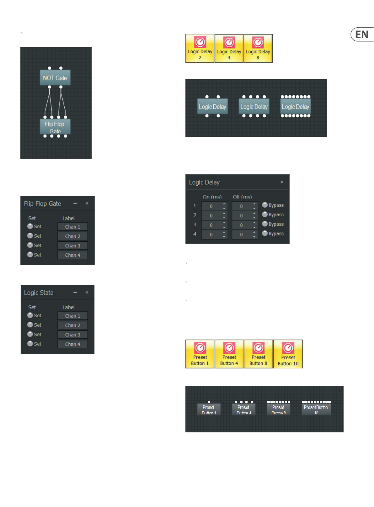
Logic Gate Module Icons
Mute Parameter Dialog Box with Control Inputs enabled.
When Control Inputs is enabled, the Mute Component Object will display logic
control terminals along the top, one logic terminal for each audio channel:
Mute Component Object with Logic Terminals
Gang Controls and Control Inputs can both be enabled at the same time, in which
case the Mute Component Object will display a ‘G’ and a single logic terminal
along the top:
Logic Gate Component Objects
Logic Gate modules func tion in the following ways:
• NOT inverts logic command cues (e.g., a HIGH input exits the module as a
LOW output, while a LOW input is inverted into a HIGH output).
• AND triggers a single output of matching polarity when ALL of the inputs are
the same (i.e., when all inputs are HIGH, the module produces a single HIGH
output; When all inputs are LOW, the module produces a single LOW output).
• NAND produces a single LOW output when ALL inputs are HIGH, while one or
more LOW inputs triggers a HIGH output.
• OR produces a single LOW output when ALL inputs LOW, while one or more
HIGH inputs triggers a HIGH output.
• NOR produces a single HIGH output when ALL inputs are LOW, while one or
more HIGH inputs triggers a LOW output.
• XOR produces a single LOW output when ALL inputs are LOW or HIGH.
HIGH inputs triggers a single HIGH output, but only when NOT ALL inputs
are HIGH (e.g., in a four-input XOR module, when three out of four inputs are
HIGH, the output will be HIGH; However, whenever ALL four inputs are HIGH,
the output will be LOW).
• Flip Flop behaves like a toggle or latching switch where a HIGH input
changes the output state, depending on how the output has been set
(e.g., when the output is set to HIGH, a HIGH input changes the output
to LOW; When the output is set to LOW, a HIGH input changes the output
to HIGH).
Mute Component Object with Ganged Logic Terminal
3.9.5 Logic Gates
Logic Gates can be placed between the logic output and logic input terminals
of other modules in the Build Window. Logic Gates can also be used to manage
control signals from GPIO connections and integrate those GPIO signals into the
DSP processing.
• Logic State modules act as manual toggle or latching switches. Logic State
modules to not have input terminals.
NOTES:
• Only NOT and Flip Flop modules have matching one-to-one inputs for every
output, while other gate types have multiple inputs for a single output.
• Only Flip Flop and Logic State modules have Control Dialog Boxes, which
are used to set these modules’ initial HIGH or LOW states.
Page 33
33 DM8000 User Manual
• Multiple Flip Flop input terminals can be connected to a single output from
another logic Gate module.
NOT Outpu ts Connected to M ultiple Flip Flop Inp uts
Right-click over a Flip Flop or Logic State Component Object to access the Control
Dialog Boxes:
Logic Delay Module Icons
Logic Delay Component Objects
Right-click to access the Component Object’s Dialog Box, with the
following controls:
Flip Flog Gat e Dialog Box
Logic State D ialog Box
In both of these Control Dialog Boxes, click on an individual channel’s Set node to
set that channel to a HIGH state. The nodes will light up green when selected.
3.9.6 Logic Delays
Logic Delays use a set time threshold to filter and delay logic control signals.
When a logic command (on or off ) arrives at a Logic Delay input terminal, the
Logic Delay module waits to see if the control signal persists beyond the userprogrammed amount of time. If the control signal continues beyond the set time
threshold, the Logic Delay will then output a signal of the same on or off type.
Logic control signals that do not persist beyond the set time threshold are not
passed on.
Logic Delay C ontrol Dialog Box
• On sets the time threshold for an “On” control signal. The On delay time can
be up to 60,000 ms/ 1 minute.
• O sets the time threshold for an “O” control signal. The O delay time can
be up to 60,000 ms/ 1 minute.
• Bypass switches o the delay function for the given channel.
3.9.7 Preset Buttons
Preset Buttons can be placed in the Build Window and programmed to set up
and recall user-created setting presets.
Preset Button Module Icons
Preset Button Component Objects
Logic Delay modules are placed in between the logic control terminals of other
logic modules and/or audio modules that generate or accept logic control signals.
Page 34

34 DM8000 User Manual
Right-click to access the Component Object’s Dialog Box, with the
following controls:
Preset Bu tton Dialog Box
Right-clicking over a button provides a list of available
• Preset ID / Preset Name pulldown menus allow you to select a user-
created Preset from the Preset list.
• Recall buttons activate and deploy the matching Preset.
3.9.8 GPIO
GPIO modules allow the DM8000 DSP to interface with external GPIO (General
Purpose Input Output) controllers via the DM8000’s GPIO port on the hardware
unit’s back panel. The GPIO por t supports 6 pins that the user can conf igure and
connect to the GPIO Volume, GPIO Select or GPIO Logic Output modules.
The GPIO Volume Parameters and GPIO Select Parameters Dialog Boxes contain
two pulldown menus:
• GPIO Number allows you to assign the module to one of the six available
pins in the GPIO port.
• GPIO Mode allows you to select between 3-wire and 2-wire congurations.
GPIO Logic O utput Parameter s Dialog Box
The GPIO Logic Output Parameters Dialog Box contains two menus:
• Outputs Count allows you to select up to ve logic outputs to the GPIO.
• GPIO Mapping allows you to assign each logic output to a specic GPIO pin
on the back panel GPIO port. When more than one logic output is specied
in the Outputs Count pulldown menu, the GPIO Mapping section will
automatically add matching pulldown menus for each logic output.
GPIO Module Icons
GPIO Component Objects
Unlike other Modules, GPIO automatically launch Parameter Dialog Windows
when placed into the Build Window, so that you can assign the GPIO modules to
specific GPIO pins in the DM8000’s GPIO port on the unit’s back panel.
GPIO Volume Par ameters and GPIO Sel ect Parameter s Dialog Boxes
Only the GPIO Volume module has a matching Control Dialog Box.
Right-click over the GPIO Volume Component Object to access the Control Dialog
Box with the following controls:
GPIO Volume Cont rol Dialog Box
• Module pulldown menu allows you to specify which module in a particular
signal processing architecture is to be controlled via GPIO.
• Channel lets you select which specic Level or Gain parameter inside the
selected module is to be linked and controlled via GPIO. Some modules may
contain multiple internal Level and Gain controls.
3.9.9 CP8000
CP8000 modules support MUSIC GROUP’s proprietar y CP8000 series of controllers.
The CP8000 series controllers (including CP8000UL and CP8000EU) are wall panel
accessories for DM8000. The CP8000 control devices allow remote control of
volume for DM8000 modules via the DM8000 GPIO port. The DM8000 GPIO port
(+5 V and GND) also acts as a remote power supply for CP8000 units.
Page 35

35 DM8000 User Manual
GPIO Port
Take note of the following considerations:
• RVC connects to one of the GPIO pins used for volume adjustment.
• AUX connects to one of the GPIO pins used for selecting which channel’s
volume is active and available for adjustment.
DM8000
CP8000EU/UL
GND
VDC
RVC
AUX
GND
+5V
GPIO 1~6
GPIO 1~6
NOTE: Once the CP8000UL/CP8000EU RVC and AUX pins each connect
to a specific DM8000 GPIO pin (1 thru 6), those pins cannot be used for
other functions.
After connecting CP8000UL/CP8000EU devices to DM8000, the user can then
use the DM8000 DSP Designer software to launch dedicated CP8000 modules for
remote configuration and control.
CP8000 Dialog Boxes
In the software, when the user chooses a new CP8000 module and drops
the module into the Build Window, the software will automatically launch a
Parameter Dialog Box so that users may select and designate specific GPIO pins
for AUX and RVC.
After selecting and assigning GPIO pins for AUX and RVC, double-click on the
CP8000 module to launch a Control Dialog Box to select which specific Input
Output Module (see “3.1 Input Output Modules”) will have its volume controlled
from the CP8000 series unit.
CP8000 Co ntrol Dialog Box f or Selection of I nput Output Mod ule and CP8000 Cont roller Button
The left-hand Module pulldown menus contain a list of Input Output Modules
available for volume control.
For example, the following screenshots show the CP8000 AUX pin being assigned
to Pin 4 of the DM8000 GPIO port, while the CP8000 RVC pin is assigned to Pin 6:
CP8000 P arameters Dialo g Box for AUX Pin Assignm ent to GPIO
CP8000 Co ntrol Dialog Box wi th Module Pulldow n Menu
The right-hand Channel pulldown menus contain a list of CP8000UL/CP8000EU
panel buttons available for assignment. (Each CP8000 device has 6 buttons on
the front panel available for assignment.)
CP8000 Co ntrol Dialog Box wi th Channel Pulldow n Menu
CP8000 P arameters Dialo g Box for RVC Pin Assignm ent to GPIO
After completing the DM8000 system design in the DM8000 DSP Designer
software, compile and download to device.
The CP8000 device can now control the assigned volume parameter as
designated in the CP8000 module.
Page 36

36 DM8000 User Manual
CP8000UL/CP8000EU Front Panel
For reference, here are the relevant front panel controls for CP8000UL:
3.10 Meters
Meter modules provide Signal Present, Peak, RMS, and Logic Meter
functions. Meter modules may be connected to any component output terminal,
and may be used for diagnostic and setup purposes, or for applications that
require real-time metering.
3.10.1 Signal Present Meter
Signal Present Meter modules indicate when an active audio signal is passing
through the assigned audio channel. A single Signal Present Meter module can be
configured to monitor multiple audio channels at once.
Signal Present Meter Module Icons
CP8000 UL and CP8000EU Fro nt Panels
1. AUXILIARY INPUT LABELING area provides space to note the name
of the assigned parameter. You may write directly on the surface or apply
sticky labels.
2. SOFT TOUCH BUTTONS can each be assigned to a separate volume
parameter. Press the button to ac tivate the volume parameter assigned to
that button. When a button is active, the embedded LED lights up.
3. VOLUME KNOB controls the level for the volume parameter selected via the
SOFT TOUCH BUTTONS. Whenever a volume parameter has been selected and
is active, the LED ring around the VOLUME KNOB will also light up.
Signal Present Component Objects
Right-click to access the Component Object’s Dialog Box, with the
following controls:
Signal Present Control Dialog Box
• Threshold determines at what level the signal present indicator will light.
• Meter Label lets you create a custom label for each channel.
In order to select and adjust a volume parameter from CP8000UL/CP8000EU,
press the SOFT TOUCH BUTTON assigned to that parameter. Both the but ton LED
and the VOLUME KNOB LED ring will light up to indicate the selected volume
parameter is active and ready for adjustment.
Page 37

37 DM8000 User Manual
3.10.2 Peak Meter
Peak Meter modules are useful for monitoring signal peaks in an
audio channel. A single Peak Meter module can be configured to monitor
multiple audio channels.
Peak Meter Module Icons
3.10.3 RMS Meter
RMS Meter modules can be used to monitor the average signal level of an
audio channel. A single RMS Meter module can be configured to monitor
multiple audio channels.
RMS Meter Module Icons
Peak Meter Component Objects
Right-click to access the Component Object’s Dialog Box, with the
following controls:
Peak Meter Con trol Dialog Box
• Hold Time controls how long the meter will show the most recent level
peak. Click on the matching node to activate the Hold Time function. The
node will light green when selected.
• Indenite Hold forces the meter to hold the highest signal peak reading.
This highest peak reading will only be updated in the display when a
subsequent signal peak exceeds the last highest reading.
• Meter Label lets you make a custom label for the audio channel
being monitored.
RMS Meter Component Objects
Right-click to access the Component Object’s Dialog Box, with the
following controls:
RMS Meter Co ntrol Dialog Box
• Hold Time controls how long the meter will show the most recent RMS
level. Click on the matching node to activate the Hold Time function. The
node will light green when selected.
• Indenite Hold forces the meter to hold the highest, most recent RMS
reading. This highest RMS reading will only be updated in the display when a
subsequent signal peak exceeds the last highest reading.
• Meter Label lets you make a custom label for the audio channel
being monitored.
Page 38

38 DM8000 User Manual
3.10.4 Logic Meter
Logic Meter modules allow you to monitor the strength of Logic commands.
Logic Meter Module Icons
Logic Meter Component Objects
Right-click to access the Component Object’s Dialog Box, with the
following controls:
Tone Generator Component Object
Right-click to access the Component Object’s Dialog Box, with the
following controls:
Tone Generator Dialog Box
• Tone mode generates a single frequency. Tone mode disables the Start
Frequency, Stop Frequency, Sweep Interval and Time Interval parameters.
• Sweep mode generates a tone that sweeps through a programmed range of
frequencies. In Sweep mode, the Frequency parameter is disabled.
Logic Mete r Dialog Box
• Indicator Node to the left lights when the logic control input terminal
receives a HIGH control signal.
• Meter Label lets you create a custom label for the given logic channel.
3.11 Generators
Generators component objects provide sine-wave, sweep, pink-noise, and
white-noise generator functions. Generators may be connected to any audio
input terminal for diagnostic and setup purposes, or for applications that require
tones or to mask other sounds.
3.11.1 Tone Generator
Tone Generator modules can generate a single tone at a set frequency, or they
can be used to sweep from a low frequency to a high frequency. These tones
can be useful for finding and dealing with problem frequencies in a room or
sound system.
• Mute turns the Tone Generator module on or o. The module is muted when
the node is lit green.
• Level controls the Tone Generator output level.
• Frequency sets the single frequency used in Tone mode.
• Start Frequency and Stop Frequency sets the frequency range for
Sweep mode.
• Sweep Interval selects the bandwidth for the Sweep tone.
• Time Interval sets how long each tone is held during a frequency sweep.
3.11.2 Pink Noise Generator
Pink Noise Generator produces pink noise (equal energy at all octaves), which
can be useful as a reference for diagnostics and setting consistent levels by ear.
Pink Noise Generator Module Icon
Tone Generator Module Icon
Pink Noise Generator Component Object
Page 39
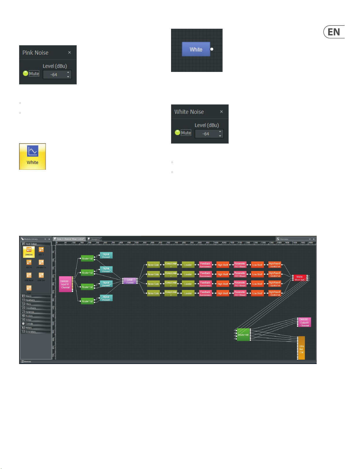
39 DM8000 User Manual
Right-click to access the Component Object’s Dialog Box, with the
following controls:
White Noise Component Objects
Pink Noise Generator Dialog Box
Right-click to access the Component Object’s Dialog Box, with the
following controls:
• Mute turns the Pink Noise Generator module on or o.
• Level sets the generator output level.
3.11.3 White Noise Generator
White Noise Generator produces white noise (flat frequency spectrum).
White Noise Dialog Box
• Mute turns the White Noise Generator module on or o.
White Noise Generator Module Icon
• Level sets the generator output level.
4. Building a Signal Processing Architecture
DM8000 Edit Software allows you to build a custom signal processing architecture by pulling connectable drag-and-drop modules from the Module Library into the
Build Window. Once in the Build Window, the modules can be arranged and connected to create the desired signal path.
Here is an example of a basic 4-channel mixer architecture:
Page 40

40 DM8000 User Manual
4.1 Deploying Component Objects
To build a custom signal processing architecture, you will need place Component
Modules into the Build Window and then connect the related Component
Objects together.
Component Objects can be placed in the Build Window by using three methods:
• Drag-and-drop from the Module Library.
• Select Component Modules from the Module Library Toolbar
• Select Component Modules from the Modules pulldown menu at the top of
the screen
4.1.1 Drag-and-Drop Method
The drag-and-drop method lets you quickly deploy standardized modules, with
minimal time spent choosing options in dialog boxes.
To drag-and-drop Component Modules directly into the Build Window, follow
these steps:
1. Go to the left side of the screen and open the Module Library of your choice.
2. Within the Module Library, click on the icon representing the
desired module.
3. While holding the mouse button, drag the module into the Build Window.
4. Place the mouse cursor over the desired location in the Build Window.
5. Release the mouse button, and the system will unzip the module and place
the module’s Component Objects in the chosen location.
6. Once deployed inside the Build Window, the Component Objects can then be
moved around on the grid as desired.
4.1.2 Module Library Toolbar Method
The Module Library Toolbar method is good when you want to customize the
Component Objects’ configuration. Choosing this method means you can close
the Module Library on the left side of the screen and therefore open up more
space in the Build Window for larger processing architectures.
To select Component Modules using the Module Library Toolbar, follow
these steps:
1. Click on the desired Component Module category in the Module Library
Toolbar (the categories are indicated by representative icons).
2. Clicking on the Module Library Toolbar icon launches a sub-menu showing
the various sub-categories.
3. Within the sub-menu categor y, click on the desire Component Module
sub-category.
4. Place the cursor over the desired location in the Build Window grid and click.
5. Clicking launches a dialog box, where you can choose customizable options.
6. Click OK, and the system will place a Component Objec t with the selected,
customized properties in the chosen location.
7. Once deployed inside the Build Window, the Component Objects can then be
moved around on the grid as desired.
4.1.3 Pulldown Menu Method
The Pulldown Menu method of fers customization of Component Objects, as well
as maximum space in the Build Window to build large processing architectures.
By strictly using the pulldown menus, the Module Libraries and Toolbars can be
hidden to provide the maximum available space for the Build Window.
To select Component Modules from the standard pulldown menus at the top of
the screen, follow these steps:
1. Click on the Modules pulldown menu tab.
2. Select the appropriate sub-menu category.
3. Within the sub-menu categor y, click on the desire Component Module
sub-category.
4. Place the cursor over the desired location in the Build Window grid and click.
5. Clicking launches a dialog box, where you can choose customizable options.
6. Click OK, and the system will place a Component Objec t with the selected,
customized properties in the chosen location.
7. Once deployed inside the Build Window, the Component Objects can then be
moved around on the grid as desired.
8. Modifying Modules in the Build Window
Once Component Modules have been placed in the Build Window, you can still
modify the Modules’ configuration. Further modifications can be made even
after the processing architecture has been compiled.
To modify Component Modules that have already been placed in the Build
Window, follow these steps:
1. Right-click over the Component Object in the Build Window, which will
launch a menu next to the cursor.
2. Click on Parameters to open the conguration dialog box.
3. Once you have chosen new parameters for the Module, click OK,
and the Component Object in the Build Window will change to show
the new conguration.
4. To exit without modications, click on Cancel.
4.1.4 Arranging Component Objects in the
Build Window
The various Component Objects inside the Build Window can be visually arranged
in a variety of ways using automated commands from the Layout Pulldown Menu
or the Module Library Toolbar:
• Order contains further sub-commands for changing the stacking order of
Component Objects in the Build Window, including Bring to Front, Send to
Back, Bring Forward and Send Backward.
• Pack Objects removes spaces and arranges Component Objects as tightly as
possible along the lef t, right, top or bottom edges.
• Align Objects straightens a group of objects along the left, right, top, or
bottom edges of the group of objects. You may also align a group of objects
by using Horizontal Center or Vertical Middle commands.
• Space Evenly equalizes the spacing in a group of objects by using Across,
Down, Vertical or Horizontal commands.
• Center in View moves the selected object or objects to the center of the
Build Window.
• Make Same Size will make a group of Component Objects all appear the
same size. This function typically will make all objects in the group the same
size as the smallest object in the selected group.
Page 41

41 DM8000 User Manual
4.1.5 Connecting Component Objects
Each Component Object features connec tion terminals for routing audio and logic
control signals between objects.
These connection terminals come in four types:
• Audio Input Terminals are always located on the left side of a
Component Object.
• Audio Output Terminals are always located on the right side of a
Component Object.
• Logic Input Terminals are always found on the top of a Component Object.
• Logic Output Terminals are always found on the bottom of a
Component Object.
As an exception, some modules, such as a Ducker, will include an additional
audio input to control the ducking process inside the module. This additional
audio input will be located below the main audio input on the left side of the
Component Object.
Connecting Terminals
To connect two terminals, follow these steps:
1. Click-and-hold the cursor over an Output Terminal.
2. While holding the mouse button, drag the cursor toward the desired Input
Terminal on the next Component Object in the signal chain. A solid line
(representing a wire) will follow the cursor out from the Output Terminal.
3. When the cursor and line approach the desired Input Terminal, the solid line
will snap from the cursor to the terminal.
4. Release the mouse button to complete the connection.
Once terminals on a set of Component Objects have been connected, the
connection lines will follow the objects and maintain the connections no matter
where you move the Component Objects in the Build Window.
NOTE: An audio output terminal or logic output terminal can be connected to
multiple Input terminals of the same type, but an input terminal of either type
cannot be connected to multiple output terminals. Similarly input and output
terminals on the same Component Object cannot be connected, and audio and
logic terminals also cannot be connected.
• Ethernet switches must be 10/100 BaseT compatible, with suffi cient ports for
connection to each DM8000 unit (multiple switches may be used).
• Ethernet has a cable length limitation of 100 meters between the Ethernet
switch and a DM8000 device. However, using ber-optic cable can extend
this length limitation to 2 km. Fiber-optic cable can be used with switches
that have ber-optic ports, or media converters can be used to interface
ber-optic cable with standard RJ-45 ports.
5.1.2 Assigning IP Addresses
When setting up an Ethernet network with multiple DM8000 units, devices in the
network will need to be set up with IP addresses. Before assigning IP addresses,
please keep in mind the following considerations:
The computer must be assigned an IP address (under Network Card
Settings>Properties). Most computers set TCP/IP address automatically, but
DM8000 devices require manual assignment. Initially, the computer IP addresses
should be assigned as 192.168.1.X (where range of X = 1 to 254).
• Each DM8000 device must also be assigned a unique IP address.
• The factory default IP address for all DM8000 devices is 192.168.1.201.
5.1.3 Sending System Design
When you have completed a Signal Processing Architecture and compiled the
design, you then need to send the compiled design to the DM8000 units in
your network by connecting your DM8000 to your PC via Ethernet (directly or
through a network).
1. Click Start Network Service either in the Design Toolbar or go to the System
pulldown menu and select Network>Start Network Service. After the
network service connects, the Status Bar at the bottom of the main screen
should display how many devices are connected.
2. Click on the Devices Panel icon in the View Toolbar to see a list of available
devices. In this window, you can review a particular device’s design, set the
device’s name and description, and set the device’s IP address.
3. Once a system design compiled and downloaded to a DM8000 device,
you can control and monitor your system in real time by using the various
dialog boxes to monitor and set levels.
5.2 System Security
5. Operation
5.1 Networking
By using Ethernet, multiple DM8000 devices can connected on a network for
system-wide programming and control
5.1.1 Ethernet Connection
When setting up an Ethernet connection to DM8000, please keep in mind the
following considerations:
• A PC computer running DM8000 DSP Designer Sof tware with Windows®
operating systems must have a 10/100 BaseT network card (NIC) installed.
• When connecting DM8000 directly to the PC’s Ethernet port, you may
select whether the DM8000’s Ethernet port uses a “cross-over” or “straightthrough” CAT5 cable to connect. (Each DM8000 ships with a straight-through
CAT5 cable.)
Device Protection Enable
Device protection can be enabled by clicking Device –> Device Protection
Devices Panel
One must first assign an administrator password that retains complete access to
the system.
The Device Protection dialog will allow the creation of an Admin password.
The password is applied by clicking the Enable Protection button.
Page 42

42 DM8000 User Manual
Device Protection Dialog
Devices Protection Dialog with Password Creation
Set the Admin Password as required.
Add/Edit User
Subsequent logins to the system at the administrator level will use the password
with “admin” as the user name.
Device Pro tection Dialo g with User Privile ge Option Shown
One must be logged on as administrator to:
• Create or edit users
• Set the device name
• Reboot the device
• Update the device’s rmware
• Disable protection for a protected system
• Reset password
• Change the access level for an account
Additional administrator functions:
Delete User – deletes user accounts.
Change Privilege – changes the privilege for the users.
Reset Password
To reset a password, click on Device Protection –> Reset Password.
Device Protection Dialog with Admin Account under Device Users
By clicking on Add User, other users can be created with one of a few system
access (privilege) levels:
There are three levels of access privilege:
• Viewer – Viewers can only read system parameters in real time, i.e., meters,
mixer controls dialogs, etc.
• Controller – Controllers can read and write system parameters in real time,
i.e., set matrix crosspoints, set levels, etc.
• Designer – Designers have the same privileges as above, including these
additional functions:
• Change and download the design
• Set the Device IP address
• Change, create and delete presets
Reset Password Dialog
To reset the Admin password, you will need a “super password” to access
the password reset function. Please contact your manufacturer to get the
super password.
Disable Protection
To disable Device Protection, you will again need to log in as Admin and click on
the Disable Protection button in the Device Protection dialog.
Page 43

43 DM8000 User Manual
Device Protection Dialog with Disable Protection Option
To confirm that you are disabling Device Protection, click on the “Yes” button
when the system asks for confirmation.
5.3 Third Party Control
DM8000 can be controlled via the RS-232 Serial Port on the rear panel
of the DM8000.
For third-party control of DM8000 functions, we have created DTP (DM8000
Text Protocol). This DTP protocol simply means that DM8000 will accept strings
of ASCII characters to control and read settings for Gain, Mute, Logic State,
Frequency, Input Level and other parameters used by DSP Processing Modules in
DM8000 products.
• DTP strings may contain a maximum of 256 characters. If a DTP string
exceeds 256 characters, the string is an invalid command.
• Sequential spaces are acceptable within the DTP string.
• Individual parameters within the DTP string may contain a maximum of
63 characters. If a parameter within a DTP string exceeds 63 characters,
the string is and invalid command, and the system will not respond
to the command.
• DTP strings should be structured in the following order:
Command InstanceTag AttributeTag Param1 Param2 Value;
In a DTP string, Param1/Param2 is the DSP module channel ID. Param1/Param2
may be required, depending on the command or attribute being referenced. If
the channel ID is not required, then Param1/Param2 should not be defined the
command. Value may be required, depending on the command or attribute being
referenced. If the command or attribute does not require it, Value should not be
defined in the command.
Examples:
set Input1 Input_Gain 1 12;
get Input1 Input_Gain 1;
set Mixer Level_State 2 3 1;
• In a set command, Value transmits the exact setting for a parameter within
a DSP module.
Example:
DTP strings can be transmitted via third-party controllers using RS-232.
A PC computer can send/receive DTP Strings by using a terminal emulator
program such as HyperTerminal.
5. 3.1 Activating Third Party Control
To activate DM8000’s Third Party Control mode, open your PC’s terminal emulator
and input “3rdStart”. (Note that the “3rdStart” command is case sensitive.)
To exit Third Party Control mode, input “exit”.
5.3.2 System Security
To protect the system, the user must input username and password to enter Third
Party Control mode. Admin can add/delete users and set/change a password by
using the PC software.
Example:
username viewer1;
password passw1;
If username and password is valid, the system will set the relevant user level and
enter Third Party Control mode.
5.3.3 Creating a DTP String
Valid DTP strings follow these principles of construc tion:
• DTP strings require a space between each parameter.
• A line feed/return or “;” needs to be placed at the end of each command
string sent.
set Input1 Input_Level 1 -12
• In an inc (increment) or dec (decrement) command, Value transmits the
amount by which a speci c parameter should change.
Example:
inc Input1 Input_Gain 1 6;
5.3.4 RS-232 Hardware Port Considerations
The RS-232 port on the back of the DM8000 unit is set to a default baud rate of
38400, 8 data bits, no parity, 1 stop bit, and no flow control (38400:8:None:1).
5.3.5 Commands
• get/set
• inc/dec
• toggle
• subscribe
• unsubscribe
• username
• password
• help – will get all valid command keys
• 3rdStart – starts Third Party Control mode
• exit – exits Third Party Control mode
• SESSION – send session speci c Attributes and Commands
• A space is not required before a line feed/return or “;”, but is acceptable.
• DTP strings may not include an illegal character. An illegal character renders
the DTP string an invalid command, and the system will not respond
to the command.
• DEVICE – send Device Services instructions or Device Attributes
and Commands.
Page 44

44 DM8000 User Manual
5.3.6 InstanceTag
All modules have one In stan ceTag attribute, which is the module alias. User can
define I nstanceTa g in the PC software. The SESSION command can return all valid
Insta nceTag list.
SESSION get aliases;
“list”:[“123 ” “AudioMeter1” “AudioMeter2” “AudioMeter3” “DEVICE”
“Input1” “Mixer1” ”Mut e1“ ”Level1“ ”Output1“]
5.3.7 Attribute
The Attribute defines the parameter of the DSP module to be controlled
(fader level, crosspoint mute, etc).
The following tables show whether each DTP Attribute supports set, get, inc, dec ,
toggle, subscribe, and unsubscribe commands, as well as the value range that the
Attribute will accept. Param1/Param2 determines whether Param1, Param2 or
BOTH are needed for a DTP String to be complete.
DTP Strings can address the following DSP modules:
• Input/Output Modules
• USB Audio Input/USB Audio Output Modules
• DM AEC Modules
• Mixer Modules
• Equalizer Modules
• Filter Modules
• Crossover Modules
• Dynamics Modules
• Router Modules
• Delay Modules
• Control Modules
• Meter Modules
• Generator Modules
• SESSION Modules
• DEVICE Modules
5.3.8 User Example
For Device Protection State is ON:
3rdStart;
username viewer1;
password passw1;
set Input1 Input_Gain 1 12;
...
exit;
For Device Protection State is OFF:
3rdStart;
set Input1 Input_Gain 1 12;
...
exit;
Page 45
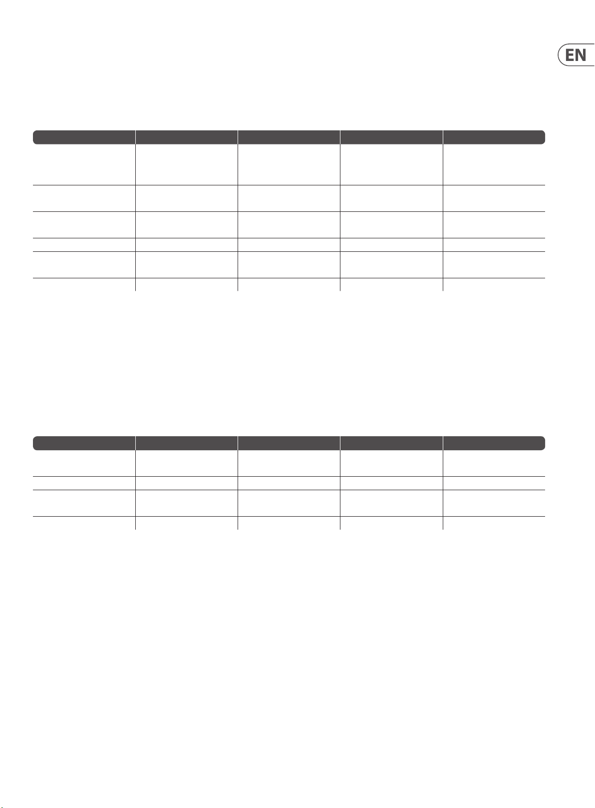
45 DM8000 User Manual
5.3.9 Tables of Module Attributes
The following tables of Attributes are valid for DM8000 processing modules:
5.3.9.1 Input Output Modules
DM8000 Input 10
Description Attribute Commands Param Value Range
Input gain Input_Gain set, get channel (value: 1 ~ 10)
Phantom power Phantom_ Power set, get, toggl e channel (value: 1 ~ 10)
Input mute Input_Mute set, ge t, toggle channel (valu e: 1 ~ 10)
Input level Input_Level set, get, inc, dec channel (value: 1 ~ 10) -100 ~ 12 dB
Input invert Invert set, get, toggl e channel (value: 1 ~ 10)
Input peak Peak subscribe, unsubscribe channel (value: 1 ~ 10) —
Examples:
0, 6, 12, 18, 24,
30, 36, 42, 48,
54, 60, 66
0 = o
1 = on
0 = unmuted
1 = muted
0 = no
1 = yes
set Input1 Input_Gain 2 18;
dec Input1 Input_Level 3 14;
Command format:command InstanceTag Attribute channel_ID value;
subscribeInput1Peak 1;
Command format:command InstanceTag Attribute channel_ID;
NOTE: This command does not require value.
DM8000 Output 6
Description Attribute Commands Param Value Range
Output mute Output_Mute set, get, toggl e channel (value: 1 ~ 6)
Output level Output_Level set, get, inc, d ec channel (value: 1 ~ 6) -100 ~ 0 dB
Invert Invert set, get, toggl e channel (value: 1 ~ 6)
Analog output level Ful lScale set, get channel (value: 1 ~ 6) -31, 0, 6, 12, 18, 24
0 = unmuted
1 = muted
0 = no
1 = yes
Examples:
set Output1 FullScale 2 -31;
dec Output1 Output_Level 3 4;
Command format:command InstanceTag Attribute channel_ID value;
toggleOutput1Output_Mute 1;
Command format:command InstanceTag Attribute channel_ID;
NOTE: This command does not require value.
Page 46
46 DM8000 User Manual
AEC Modules
DM AEC Attribute Commands Param Value Range
AEC enabled value AEC_Enabled set, g et, toggle
Noise reduction value N oise_Reduction set, get
Non-linear process mode Non_linear_process set, get
Min threshold value Min_Threshold set, get, inc, dec
AEC ref / mic / o ut / REL / ERLE /
TER value
AEC_Status_1 subscribe, unsubscribe
channel (value: 1 ~ chan nel_count
(max : 8))
channel (value: 1 ~ chan nel_count
(max : 8))
channel (value: 1 ~ chan nel_count
(max : 8))
channel (value: 1 ~ chan nel_count
(max : 8))
channel (value: 1 ~ chan nel_count
(max : 8))
Examples:
set AEC1 Noise_Reduction 2 8;
Command format:command InstanceTag Attribute channel_ID value;
0 = AEC mode di sable
1 = AEC mode en able
0 = o
1 = low
2 = soft
3 = medium
4 = aggressive
0 = o
1 = soft
2 = medium
3 = aggressive
-100 ~ 0 dB
—
decAEC1Min_Threshold 3 7;
Command format:command InstanceTag Attribute channel_ID value;
subscribeAEC1AEC_Status_1 1;
Command format:command InstanceTag Attribute channel_ID;
NOTE: This command does not require value.
USB Input Modules
Description Attribute Commands Param Value Range
Input mute Input_Mute set, get, toggle channel (va lue: 1, 2)
Input level Input_Level set, get, in c, dec channel (value: 1, 2) -100 ~ 12 dB
Input invert Invert set, get, toggl e channel (valu e: 1, 2)
USB input s tatus USB_Input_Status subscribe, unsubscribe — —
Examples:
set UsbInput1 Input_Level 2 -18;
Command format:command InstanceTag Attribute channel_ID value;
toggleUsbInput1Inverted 1;
Command format: command InstanceTag Attribute channel_ID;
0 = unmuted
1 = muted
0 = no
1 = yes
NOTE: This command does not require a value.
subscribeUsbInput1USB_Input_Status;
Command format: command InstanceTag Attribute;
NOTE: This command does not require channel_ID or value.
Page 47

47 DM800 0 User Manual
USB Output Modules
Description Attribute Commands Param Value Range
Output mute Output_Mute set, get, toggl e channel (value: 1, 2)
Output level Output_Level set, get, inc, d ec channel (valu e: 1, 2) -10 0 ~ 0 dB
Output invert In vert se t, get, toggle channel (va lue: 1, 2)
USB output status USB_Input_Status subscribe, unsubscribe — —
Examples:
set UsbOutput1 Output_Level 2 -31;
Command format:command InstanceTag Attribute channel_ID value;
getUsbOutput1Output_Level1;
Command format:command InstanceTag Attribute channel_ID;
NOTE: This command does not require value.
toggleUsbOutput1Output_Mute1;
Command format:command InstanceTag Attribute channel_ID;
NOTE: This command does not require value.
0 = unmuted
1 = muted
0 = no
1 = yes
5.3.9.2 Mixers
Auto Mixer
Description Attribute Commands Param Value Range
Input mute Input_Mute set, ge t, toggle channel (value: 1 ~ inpu t_count (max : 32))
Input level Input_Level set, get, inc, dec channel (value: 1 ~ inpu t_count (max : 32)) -100 ~ 12 dB
Input level state Level_State set, get, toggl e channel (value: 1 ~ input_ count (max: 32))
Mix output mute Mix_Output set, ge t, toggle —
Mix output level Mix_Level set, get, inc, dec — -100 ~ 12 dB
Mic logic Mic_Logic set, get —
Logic outputs follow mic logic Logic_Outs_Follow set, get, toggl e —
Open mic limits enabled OML_Enabled se t, get, toggle —
Open mic li mits open
microphone number
Channel direct output Channel_1_Direct_Output set, get, toggle channel (value: 1 ~ inp ut_count (ma x: 32))
Channel manual Channel_1_Manual set, get, toggle channel (value: 1 ~ in put_coun t (max: 32))
Channel NOM gain enable Channel_1_NOM_Gain_Enable set, get, toggl e channel (val ue: 1 ~ input_ count (max: 32))
Channel o attenuation Channel_1_O_Attenuation_dB set, get, inc, d ec channel (value: 1 ~ input_ count (max: 32)) -80 ~ -10
Channel gate hold time Channel_1_Gate_Hold_Time_ms set, ge t, inc, dec channel (value: 1 ~ inpu t_count (max : 32)) 1 ~ 6000
Output logic Logic _1 set, get
Output invert Inverted set, ge t, toggle
OML_Max_Open_ Mics set, get, inc, d ec — 0 ~ channel _number-1
channel (value: 1 ~ logicout_count
(max: 32))
channel (value: 1 ~logicout_count
(max: 32))
0 = unmuted
1 = muted
0 = o
1 = on
0 = unmuted
1 = muted
0 = none
1 = last mic ho ld
2 = input 1
0 = no
1 = yes
0 = no
1 = yes
0 = post-g ate / pre-nom
1 = post-g ate / post-nom
0 = o
1 = on
0 = o
1 = on
0 = follow ga te
1 = on
2 = o
0 = no
1 = yes
Page 48
48 DM8000 User Manual
Examples:
setMixer1Input_Mute 2 1;
Command format: command InstanceTag Attribute channel_ID value;
dec Mixer1Mix_Level 11;
Command format:command InstanceTag Attribute value;
NOTE: This command does not require a channel_ID.
toggle Mixer1NOM_Gain_Enable 3;
Command format:command InstanceTag Attribute channel_ID;
NOTE: This command does not require a value.
Standard Mixer
Description Attribute Commands Param Value Range
Input mute Input_Mute set, ge t, toggle channel (value: 1 ~ inpu t_count (max : 32))
Input level Input_Level set, get, inc, dec channel (value: 1 ~ inpu t_count (max : 32)) -100 ~ 12 dB
Output mute Output_mute set, get, toggle channel (value: 1 ~ o utput_ count (max: 24))
Output level Output_Level set, get, inc, d ec channel (value: 1 ~ out put_cou nt (max: 24)) -100 ~ 12 dB
Level state Level _State set, get, toggle
input_ch, output_ch (input_ ch value: 1 ~
input _count (max 32); outpu t_ch value: 1
~ output _count (max: 24))
Examples:
0 = unmuted
1 = muted
0 = unmuted
1 = muted
0 = o
1 = on
setMixer2Input_Mute 2 1;
Command format:command InstanceTag Attribute channel_ID value;
toggleMixer2Output_Mute 1;
Command format:command InstanceTag Attributechannel_ID;
NOTE: This command does not require a value.
setMixer2Level_State 2 1 3;
Command format:command InstanceTag Attribute channel_ID1 channel_ID2 value;
NOTE: This command requires t wo Channel_ID designations.
Matrix Mixer
Description Attribute Commands Param Value Range
Input mute Input_Mute set, ge t, toggle
Input level Input_Level set, get, inc, dec
Output mute Output_mute set, get, toggle
Output level Output_Level set, get, inc, d ec
Level Level s et, get, inc, dec
Level state Level _State set, get, toggle
input_ch (value: 1 ~ inp ut_count
(max: 32))
input_ch (value: 1 ~ inp ut_count
(max: 32))
output_ch (value: 1 ~ out put_coun t
(max : 24))
output_ch (value: 1 ~ out put_coun t
(max : 24))
input_ch, output_ch (input_ ch value: 1 ~
input _count (max: 32); outp ut_ch valu e:
1 ~ output _count (max: 24))
input_ch, output_ch (input_ ch value: 1 ~
input _count (max: 32); outp ut_ch valu e:
1 ~ output _count (max: 24))
NOTE: Level_State can support set commands for whole rows/columns and all cross points:
0 = unmuted
1 = muted
-100 ~ 12 dB
0 = unmuted
1 = muted
-100 ~ 12 dB
-100 ~ 0 dB
0 = o
1 = on
Command InstanceTag Level_State A value;
Command InstanceTag Level_State R row_line value;
Command InstanceTag Level_State C column_line value;
Page 49

49 DM8000 User Manual
Mixer Matrix w/ Delay
Description Attribute Commands Param Value Range
Input mute Input_Mute set, ge t, toggle input_ch (value: 1 ~ inpu t_count (ma x: 32))
Input level Input_Level set, get, inc, dec input_ch (value: 1 ~ inpu t_count (ma x: 32)) -100 ~ 12 dB
Output mute Output_mute set, get, toggle output_ ch (value: 1 ~ out put_co unt (max: 24))
Output level Output_Level set, get, inc, d ec output_ch (value: 1 ~ outpu t_coun t (max: 24)) -100 ~ 12 dB
Level Level s et, get, inc, dec
Delay Delay set, get, inc, dec
Level state Level _State set, get, toggle
Delay st ate Delay_ State set, get, tog gle
input_ch, output_ch (input_ ch value: 1 ~
input _count (max: 32); outp ut_ch valu e:
1 ~ output _count (max: 24))
input_ch, output_ch (input_ ch value: 1 ~
input _count (max: 32); outp ut_ch valu e:
1 ~ output _count (max: 24))
input_ch, output_ch (input_ ch value: 1 ~
input _count (max: 32); outp ut_ch valu e:
1 ~ output _count (max: 24))
input_ch, output_ch (input_ ch value: 1 ~
input _count (max: 32); outp ut_ch valu e:
1 ~ output _count (max: 24))
5.3.9.3 Equalisers
Parametric Equaliser
Description Attribute Commands Param Value Range
EQ center frequency Center_Frequence set, ge t, inc, dec band (value: 1 ~ ban d_count (max: 16)) 20 ~ 2000 0 Hz
EQ lter gain Filter_Gain set, get, inc, de c band (valu e: 1 ~ band_coun t (max: 16)) -30 ~ 15 dB
EQ band wi dth Bandwidth set, get, in c, dec band (value: 1 ~ band _count (max: 16)) 0.01 ~ 4
EQ band byp ass Bypass _Band set, get, toggle band (va lue: 1 ~ band_co unt (max: 16))
EQ bypas s all Bypass_All set, get, tog gle —
0 = unmuted
1 = muted
0 = unmuted
1 = muted
-100 ~ 0 dB
0 ~ 1000 ms
0 = o
1 = on
0 = o
1 = on
0 = no
1 = yes
0 = no
1 = yes
Graphic Equaliser
Description Attribute Commands Param Value Range
EQ lter gain Filter_Gain set, get, inc, de c band (1 ~ available band _count) -30 ~ 15 dB
EQ band byp ass Bypass _Band set, get, toggle band (1 ~ available b and_count)
EQ bypas s all Bypass_All set, get, tog gle —
Feedback Suppressor
Description Attribute Commands Param Value Range
EF center frequency Center_Frequence set, ge t, inc, dec band (value: 1 ~ ban d_count (max: 16)) 20 ~ 2000 0 Hz
EF lter gai n Filter_Gain se t, get, inc, dec band (value: 1 ~ b and_count (ma x: 16)) -30 ~ 0 dB
EF bandwidth octaves Bandwidth_octaves set, get, inc, dec band (valu e: 1 ~ band_coun t (max: 16)) 0.01 ~ 4
EF x band by pass Fix_Band set, get, to ggle band (value: 1 ~ band _count (max: 16))
EF band byp ass Bypass_Band set, ge t, toggle band (value: 1 ~ ban d_count (max : 16))
EF max dept h Max_Depth set, get, inc, dec — -20 ~ 0
EF width Width set, get, toggle —
EF x all ban d Fix_All set, get, toggl e —
EF bypass a ll Bypass _All set, get, toggle —
EF feedback reset all Feedback_Re setAll set —
Feedback status Feedback_Status subscribe, unsubscribe — —
0 = no
1 = yes
0 = no
1 = yes
0 = no
1 = yes
0 = no
1 = yes
0 = narrow
1 = wide
0 = no
1 = yes
0 = no
1 = yes
0 = no
1 = yes
Page 50

50 DM8000 User Manual
5.3.9.4 Filters
High Pass/Low Pass
Description Attribute Commands Param Value Range
Cuto frequency Cuto_Frequency set, g et, inc, dec — 20 ~ 20000 Hz
-48 dB/oct .:
0 = L-R 12 1 = L-R 24
2 = L-R 36 3 = L-R 48
4 = BW 6 5 = BW 12
Filter type slope Filter_Type_Slope set, get —
Filter bypass Bypass se t, get, toggle —
6 = BW 18 7 = BW 24
8 = BW 30 9 = BW 36
10 = BW 42 11 = BW 48
-24 dB /oct .:
0 = L-R 12 1 = L-R 24
2 = BW 6 3 = BW 12
4 = BW 18 5 = BW 24
High Shelf/Low Shelf
Description Attribute Commands Param Value Range
Cuto frequency Cuto_Frequency set, g et, inc, dec — 20 ~ 20000 Hz
Shelf lt er gain Filter_Gain set, get, inc , dec — -27 ~ 9 dB
Filter bypass Bypass se t, get, toggle —
0 = no
1 = yes
0 = no
1 = yes
All Pass
Description Attribute Commands Param Value Range
Center frequency Center_Frequence set, get, inc, dec band (1 ~ band _count (max: 16)) 20 ~ 20 000 Hz
Bandwidth octaves Bandwidth_octaves set, get, inc, dec band (1 ~ band_cou nt (max: 16)) 0.01 ~ 4
Band bypass Bypass_Ban d se t, get, toggle band (1 ~ band_ count (max: 16))
Bypass all Bypass_All set, ge t, toggle band (1 ~ band_co unt (max: 16))
5.3.9.5 CrossOvers
2-Way/3-Way/4-Way Modules
Description Attribute Commands Param Value Range
Input mute Input_Mute set, ge t, toggle —
Input level Input_Level set, get, inc, dec — -100 ~ 12 dB
Output mute Output_mute set, get, toggle way_ num (1 ~ way_count)
Output level Output_Level set, get, inc, d ec way_nu m (1 ~ way_count) -100 ~ 0 dB
Output polarity Output_Polarity set, get, toggle way_n um (1 ~ way_count)
Cuto frequency Cuto_Frequency set, g et, inc, dec way_num (1 ~ way_ count) 20 ~ 20 000 Hz
0 = no
1 = yes
0 = no
1 = yes
0 = unmuted
1 = muted
0 = unmuted
1 = muted
0 = no
1 = yes
Page 51

51 DM8000 User Manual
2-Way/3-Way/4-Way Modules (Cont'd)
Description Attribute Commands Param Value Range
-48 dB/oct .:
0 = L-R 12 1 = L-R 24
2 = L-R 36 3 = L-R 48
4 = BW 6 5 = BW 12
6 = BW 18 7 = BW 24
Filter type slope Filter_Type_Slope set, get way_n um (1 ~ way_count)
Synchronize Synchronize s et, get, toggle —
8 = BW 30 9 = BW 36
10 = BW 42 11 = BW 48
-24 dB /oct .:
0 = L-R 12 1 = L-R 24
2 = BW 6 3 = BW 12
4 = BW 18 5 = BW 24
5.3.9.6 Dynamics
Leveler Modules
Description Attribute Commands Param Value Range
Response time Response_Time set, get, inc, dec — 0.1 ~ 40000 m s
Threshold Threshold set, get, i nc, dec — -60 ~ 24 dB u
Bypass Bypass se t, get, toggle —
Dynamic leveler status Leveler_Sta tus subscribe, unsubscribe — —
0 = no
1 = yes
0 = no
1 = yes
CompLimiter
Description Attribute Commands Param Value Range
Attack t ime Attack_Time set, get, inc, dec — 0.1 ~ 2000 ms
Response time Response_Time set, get, inc, dec — 0.1 ~ 40000 m s
Compress ratio Compress_Ratio set, get, inc , dec — 1 ~ 100
Threshold Threshold set, get, i nc, dec — -60 ~ 24 dB u
Bypass Bypass se t, get, toggle —
Dynamic leveler status Leveler_Sta tus subscribe, unsubscribe — —
Ducker
Description Attribute Commands Param Value Range
Input mute Input_Mute set, ge t, toggle —
Input level Input_Level set, get, inc, dec — -100 ~ 12 dB
Sense mute Sense set, get, toggl e —
Sense level Sense_Level set, g et, inc, dec — -100 ~ 12 dB
Threshold Threshold set, get, i nc, dec — -60 ~ 24 dB u
Ducking level Ducking_ Level set, get, inc, d ec — -100 ~ 0 dB
Attack t ime Attack_Time set, get, inc, dec — 0.1 ~ 2000 ms
Release time Release_Time set, get, inc, dec — 0.1 ~ 40000 m s
Logic in enable Enable_Logic_In set, get, to ggle —
Logic in invert Invert_Logic_In set, get, toggl e —
Logic output enable Enable_Logic_Out set, get, toggl e —
0 = no
1 = yes
0 = unmuted
1 = muted
0 = unmuted
1 = muted
0 = no
1 = yes
0 = no
1 = yes
0 = no
1 = yes
Page 52

52 DM8000 User Manual
Description Attribute Commands Param Value Range
Logic ou tput invert Invert_Logic_Out set, get, toggl e —
Mix sense Mix_Sense set, ge t, toggle —
Bypass Bypass se t, get, toggle —
5.3.9.7 Noise Gate
Noise Gate
Description Attribute Commands Param Value Range
Attack t ime Attack_Time set, get, inc, dec — 0.1 ~ 2000 ms
Release time Release_Time set, get, inc, dec — 0.1 ~ 40000 m s
Threshold Threshold set, get, i nc, dec — -60 ~ 24 dB u
Bypass Bypass se t, get, toggle —
Noise gate status NoiseGate_Status subscribe, unsubscribe — —
5.3.9.8 ANC (Ambient Noise Compensator)
0 = o
1 = on
0 = no
1 = yes
0 = no
1 = yes
0 = no
1 = yes
ANC Module
Description Attribute Commands Param Value Range
Dynamic program mute Program_M ute set, get, toggl e —
Dynamic program level Progra m_Level set, get, i nc, dec — -100 ~ 12 dB
Ambient mute Ambient_Mute set, ge t, toggle —
Ambient level Ambient_Level set, get , inc, dec — -100 ~ 12 dB
Ambient threshold Ambient_Threshold set, get, inc, dec — -60 ~ 24 dBu
Ambient response Ambient_Response set, get, inc, dec — 500 ~ 300000 ms
Minimum gain Min_Gain set, get, i nc, dec — -25 ~ 10
Maximum gain Max_Gain set, get, inc, dec — 10 ~ 25
Gain rat io Gain_Ratio set, get, inc, d ec — 0.25 ~ 4
Time Time set, get, inc, dec — 500 ~ 300000 ms
Bypass Bypass se t, get, toggle —
ANC prog, a mb, gain ANC_Sta tus subscribe, unsubscribe — —
5.3.9.9 Routers
In/Out Routers
Description Attribute Commands Param Value Range
Router on Router_On set, get, toggl e
in, out (in val ue: 1 ~ in_count (ma x: 32),
out value : 1 ~ out_count (ma x: 32))
0 = unmuted
1 = muted
0 = unmuted
1 = muted
0 = no
1 = yes
0 = o
1 = on
Note: Router_On can support set whole row cross point:
Command InstanceTag Router_On R row_line value;
Source Selection
Description Attribute Commands Param Value Range
Selec ted source ID Selected_ Source se t, get, inc, dec — 1 ~ available source channel_count
Source level Level set , get, inc, dec
channel (1 ~ available s ource channel _
count (max : 16))
-100 ~ 12
Page 53

53 DM8000 User Manual
5.3.9.10 Delays
Delay Modules
Description Attribute Commands Param Value Range
Delay unit Units set, get —
Delay value Delay_value set, get , inc, dec — 0 ~ max
Bypass Bypass se t, get, toggle —
5.3.9.11 Controls
Level Control
Description Attribute Commands Param Value Range
Level mute Muted set, g et, toggle channel (1 ~ channe l_count (max: 16))
Level value Level_dB set, get, inc, de c channel (1 ~ channel_cou nt (max: 16)) -100 ~ 12 dB
Maximum level value Maximum set, get, inc, d ec channel (1 ~ channel_co unt (max: 16)) m in ~ 12 dB
Minimum level value Minimum set, get, inc, dec channel (1 ~ ch annel_coun t (max: 16)) -100 ~ max
0 = millise conds
1 = centimeters
2 = meters
3 = inches
4 = feet
0 = no
1 = yes
0 = unmuted
1 = muted
Level Control (Ganged)
Description Attribute Commands Param Value Range
Level mute Muted set, g et, toggle —
Level value Level_dB set, get, inc, de c — -100 ~ 12 dB
Maximum level value Maximum set, get, inc, d ec — min ~ 12 dB
Minimum level value Minimum set, get, inc, dec — -100 ~ max
Level Inc/Dec
Description Attribute Commands Param Value Range
Level mute Muted set, g et, toggle channel (1 ~ channe l_count (max: 16))
Level value Level_dB set, get, inc, de c channel (1 ~ channel_cou nt (max: 16)) -100 ~ 12 dB
Maximum level value Maximum set, get, inc, d ec channel (1 ~ channel_co unt (max: 16)) m in ~ 12 dB
Minimum level value Minimum set, get, inc, dec channel (1 ~ ch annel_coun t (max: 16)) -100 ~ max
Inc and dec l evel value Level_ Inc_Dec set, get, inc , dec channel (1 ~ channel_c ount (max: 16)) 1 ~ 15
Ramp rate Ramp_Rate set, ge t, inc, dec channel (1 ~ channel _count (max: 16)) 100 ~ 1000
Level ram p status LevelRamp_Sta tus subscribe, unsubscribe channel (1 ~ channel_ count (max: 16)) —
Level Inc/Dec (Ganged)
Description Attribute Commands Param Value Range
Level mute Muted set, g et, toggle —
Level value Level_dB set, get, inc, de c — -100 ~ 12 dB
Maximum level value Ma ximum set, get, inc, dec — min ~ 12 dB
Minimum level value Minimum set, get, inc, dec — -100 ~ max
Inc and dec l evel value Level_ Inc_Dec set, get, inc , dec — 1 ~ 15
Ramp rate Ramp_Rate set, ge t, inc, dec — 100 ~ 1000
Level ram p status LevelRamp_Sta tus subscribe, unsubscribe — —
0 = unmuted
1 = muted
0 = unmuted
1 = muted
0 = unmuted
1 = muted
Page 54

54 DM8000 User Manual
Invert
Description Attribute Commands Param Value Range
Invert Invert set, get, toggl e channel (1 ~ channel_co unt (max: 16))
Invert (Ganged)
Description Attribute Commands Param Value Range
Invert Invert set, get, toggl e —
Mute
Description Attribute Commands Param Value Range
Mute Muted se t, get, toggle channel (1 ~ chann el_count (max : 16))
Mute status Mute_Sta tus subscribe, unsubscribe channel (1 ~ channel_ count (max: 16)) —
Mute (Ganged)
Description Attribute Commands Param Value Range
Mute Muted se t, get, toggle —
Mute status Mute_Sta tus subscribe, unsubscribe — —
0 = no
1 = yes
0 = no
1 = yes
0 = unmuted
1 = muted
0 = unmuted
1 = muted
Logic State
Description Attribute Commands Param Value Range
State State set, get, tog gle channel
Logic Delays
Description Attribute Commands Param Value Range
Logic on delay value O n_Delay set, get, inc , dec channel (1 ~ channel_co unt (max: 16)) 0 ~ 60000 ms
Logic o delay value O_D elay set, ge t, inc, dec channel (1 ~ channel _count (max: 16)) 0 ~ 6000 0 ms
Bypass Bypass se t, get, toggle channel (1 ~ chann el_count (max : 16))
5. 3.9.12 GPIO
GPIO Volume
Description Attribute Commands Param Value Range
GPIO_ID GPIOID get — —
GPIO volume
control module
info
VolumeModuleInfo get — —
Examples:
get Volume1 VolumeModuleInfo;
0 = o
1 = on
0 = no
1 = yes
get Volume1 GPIOID;
Page 55

55 DM8000 User Manual
GPIO Select
Description Attribute Commands Param Value Range
GPIO_ID GPIOID get — —
Examples:
get Select1 GPIOID;
GPIO Logic Output
Description Attribute Commands Param Value Range
GPIO_ID GPIOID get — —
GPIO outp ut count Number get — —
Examples:
get LogicOutput1 GPIOD;
get LogicOutput1 Number;
GPIO WallPanel
Description Attribute Commands Param Value Range
GPIO volum e ID VolumeGPIO get — —
GPIO sele ct ID SelectGPIO get — —
GPIO control module info WallPanelModuleInfo ge t —
Examples:
get WallPanel1 VolumeGPIO;
get WallPanel1 WallPanelModuleInfo;
5.3.9.13 Meters
Signal Present
Description Attribute Commands Param Value Range
Threshold Threshold set, get, i nc, dec channel (1 ~ channel_ count (max: 16)) -64 ~ 30 dBu
Meter sig p resent sta tus SigPresent_Status subscribe, unsubscribe channel (1 ~ channel_coun t (max: 16)) —
Peak Meter
Description Attribute Commands Param Value Range
Peak hold t ime Hold_Time set, get, inc, dec channel (1 ~ ch annel_coun t (max: 16)) 0 ~ 200 0 ms
Peak hold Peak_Hold set, get, toggle channel (1 ~ chan nel_count (ma x: 16))
Indenite peak hold Indenite_Peak_Hold set, get, toggle channel (1 ~ channel_ count (max: 16))
Meter pea k status Peak_Status subscribe, unsubscribe channel (1 ~ channel _count (max: 16)) —
RMS Meter
Description Attribute Commands Param Value Range
RMS hold time Hold_Time se t, get, inc, dec channel (1 ~ channe l_count (max: 16)) 0 ~ 2000 m s
RMS hold RMS_Hold set, get, toggle channel (1 ~ chan nel_count (ma x: 16))
Indenite RMS hold Indenite_RMS_Hold set, get, togg le channel (1 ~ channel_ count (max: 16))
Meter RM S status RMS _Status subscribe, unsubscribe channel (1 ~ channel_coun t (max: 16)) —
0 = no
1 = yes
0 = no
1 = yes
0 = no
1 = yes
0 = no
1 = yes
Page 56

56 DM8000 User Manual
5.3.9.14 Generators
Tone Generator
Description Attribute Commands Param Value Range
Level mute Muted set, g et, toggle —
Level value Leve l set, get, i nc, dec — -100 ~ 36 dBu
Frequency Frequency se t, get, inc, dec — 20 ~ 20000 Hz
Sweep Sweep set, ge t, toggle —
Start frequency Start_Frequency set, g et, inc, dec — 20 ~ Stop_Freq uency
Stop frequency Stop_Frequency set, get, inc, de c — Start_Frequency ~ 20000
Sweep interval Sweep_Inter val set, get —
Interval time Time _Interval set, get, i nc, dec — 100 ~ 60000 ms
0 = unmuted
1 = muted
0 = no
1 = yes
0 = 1 octav e
1 = 2/3 oc tave
2 = 1/3 octav e
3 = 1/6 octave
4 = 1/12 octave
5 = narrow b and
Pink Noise Generator
Description Attribute Commands Param Value Range
Pink output mute Mute set, ge t, toggle —
Pink out put level Level set, get, inc, d ec — -100 ~ 36 dBu
0 = unmuted
1 = muted
White Noise Generator
Description Attribute Commands Param Value Range
White output mute Mute s et, get, toggle —
White output level Level s et, get, inc, dec — -100 ~ 36 dBu
0 = unmuted
1 = muted
Page 57

57 DM8000 User Manual
5. 3.10 Other Attributes
DEVICE
Description Service Value
Recall a p reset recallPreset Pres et ID (Integer)
Note: recallPreset commands should take the following form:
DEVICE recallPreset presetID;
Description Attribute Code Command Indexes Value Range
Host name hostname get — —
Network interface cong ipCong get — —
Network status networkStatus get — —
Serial number serialNumber get — —
Firmware version version get — —
Example:
DEVICE get ipCong;
DM8000 Network Interface Cong {“ip”:“192.1 68.1. 22 ”
“netmask”: “255.255.255. 0” “gateway”:“0.0.0.0”}
SESSION
Description Attribute Code Command Indexes Value Range
Aliases aliases get — —
Example:
SESSION get aliases;
“list”:[“123 ” “AudioMeter1” “AudioMeter2” “AudioMeter3” “DEVICE”
“Input1” “Mixer1” “Mut e1” “Level1” “Output1”]
Page 58

58 DM8000 User Manual
6. Index
2
2-Way Crossover, 6, 22
3
3-Way Crossover, 6, 22
4
4-Way Crossover, 6, 22
A
Acoustic Echo Cancellation (AEC), 13, 15
Active Band (parameter), 19, 20, 22,
AEC (modules), 15, 39,
AEC (Acoustic Echo Cancellation), 13, 15
AEC 1 (modules), 15
AEC Advanced Dialog Box, 15
AEC N (modules), 15
AEC Ref 8 Channel, 15
AEC, Typical Design, 15
AEC, Typical System, 15
Align Objects, 8, 11, 37
All-Pass Filter (module), 6, 20-21
Amb Meter (parameter), 25, 38
Ambient Label (parameter), 25
Ambient Level (parameter), 25, 38, 43
Ambient Mute (parameter), 25, 43
Ambient Noise Compensator (ANC) (module), 6, 22, 24,
Ambient Response (parameter), 25, 38, 43
Ambient Threshold (parameter), 25, 38, 43
ANC (Ambient Noise Compensator) (module), 6, 22, 24, 38, 43
ANC (Automatic Noise Cancellation), 25, 38
ANC Setup Procedure, 25, 38
AND Gate (modules), 31
Arranging Component Objects in the Build Window, 37
Assign Matrix, 18
Assigning IP Addresses Procedure, 39
Attack Time (parameter), 23, 24, 42,
Audio Input Terminals, 37, 38
Audio Output Terminals, 37, 38
Auto Mixers (modules), 16-17
Automatic Noise Cancellation (ANC), 25, 38
Automatic Noise Cancellation (ANC) Setup Procedure, 38
Automatic Noise Cancellation (ANC) Setup Procedure, Making Connections, 28
Automatic Noise Cancellation (ANC) Setup Procedure, Setting Gain Min and
Gain Max, 38
Automatic Noise Cancellation (ANC) Setup Procedure, Setting Response Times, 38
B
Background Color, 7
Band (parameter), 19, 22, 41
Bandwidth (parameter), 19, 20, 22, 41
Basic Screen Elements, 4
Bold (text format), 7
Border Color, 7
Build Toolbar, 8, 11
Build Toolbar Elements, 8
Build Window, 4-10, 13, 15, 16, 19, 20, 22, 26-30, 36-38
Bypass (parameter), 15, 20-26, 32, 41-44
Bypass All (parameter), 19, 20, 22, 41
Bypass Band (parameter), 19, 20, 41
C
Center (parameter), 7, 8, 11, 37
Center Freq. (parameter), 19, 20, 22,
Center in View, 8, 11, 37
Channel Settings, 17
Close (file command), 9, 11
Close All (file command), 9, 11
Co mpi le, 8-10 , 12-13
Compile Output Panel, 9-10, 12, 13
CompLimiter (module), 6, 22, 23, 42
Component Objects (explained), 13
Connecting Component Objects Procedure, 37
Connecting Terminals Procedure, 38
Content (command), 9, 11
Control Dialog (command), 10
Control Inputs (parameter), 30,
Controls (modules), 6, 26
Copy (command), 9, 10
Copy DSP Data (command), 10
CrossOvers (modules), 6, 22
2-Way, 22
3-Way, 2 2
4-Way, 22
Cut (command), 9-10
Cutoff Freq. (parameter), 20-21
Cutoff Frequency (parameter), 22
Page 59

59 DM8000 User Manual
D
Delay Value (parameter), 26
Delays (modules), 6, 26
Delay Value (parameter), 26
Units, 26, 43
Delete (command), 9, 10
Deploying Component Objects Procedure, 36
Deploying Component Objects Procedure, Drag-and-Drop Method, 36
Deploying Component Objects Procedure, Module Library Toolbar Method, 37
Deploying Component Objects Procedure, Pulldown Menu Method, 37
Designated Mic On (parameter), 17
Device Info, 12
Device Information Display, 12
Device Panel, 9-10, 12
Direct Output (parameter), 17, 40
DM8000 Input 10 Channel, 13-14
DM8000 Output 6 Channel, 13-14, 38
Download Design to Device (command), 8, 10
Drag Points (parameter), 19-20, 22
DSP, 13-15, 20, 30, 32
DSP Operation Toolbar, 8
Ducker (modules), 6, 22-24, 37
Ducking Level (parameter), 24, 42
Duplicate (command), 10
Dynamics (modules), 6, 22
ANC (Ambient Noise Compensator), 24-25, 38, 43
CompLimiter, 6, 22, 24, 42
Ducker, 6, 22-24, 37, 42
Leveler, 6, 22-23, 42
Noise Gate, 6, 22, 24, 42
E
Edit Mode, 8
Edit Pulldown Menu, 10
Edit Text (command), 10, 16
Enable Logic (parameter), 26, 42
Enable Ramping (parameter), 28-29
Rate (parameter), 28-29, 44
Enter Editing Mode (command), 8, 10
Ethernet, 4, 12, 38-39
Ethernet Connection, 38
Ethernet switch, 38
Ethernet, Cable Length, 38
Exit (command), 9
F
Feedback Suppressor (modules), 20, 41
Fiber-optic cable, 38
File Pulldown Menu, 9
Filter (modules), 6, 20-22
All-Pass, 6, 20-22
High Pass, 6, 20-21
High Shelf, 6, 21
Low Pass, 6, 20-21
Low Shelf, 6, 21-22
Filter Slope (parameter), 20
Filter/Slope (parameter), 21-22
Firmware Upgrade Manager, 10, 12
Fix All (parameter), 20, 41
Fix Band (parameter), 20, 41
Flatten All (parameter), 19
Flatten Band (parameter), 19
Flip Flop (parameter), 31, 44
Flip Flop Gate (modules), 31
Font, 7
Font Size, 7
ForeColor, 7
Format Toolbar, 7
Frequency (parameter), 22, 35, 41-42, 45
Full Scale (parameter), 14, 19-20
G
Gain (parameter), 14, 19-21
Gain Max (parameter), 25, 38
Gain Meter (parameter), 25
Gain Min (parameter), 25, 38
Gain Ratio (parameter), 25, 43
Gain Time (parameter), 25, 38
Gang Controls (parameter), 27-30
Ganged Controls, 27-30
Gate Hold Time (parameter), 17, 40
Generators (modules), 6, 35-36
GPIO (General Purpose In Out), 30, 32-33
GPIO (modu les), 32-33
GPIO Logic Output (modules), 32-33
GPIO Logic Output, GPIO Mapping (parameter), 33
GPIO Logic Output, Outputs Count (parameter), 33
GPIO Mapping (parameter), 33
GPIO Mode (parameter), 33
Page 60

60 DM8000 User Manual
GPIO Number (parameter), 33
GPIO Port (hardware panel), 32-33
GPIO Select (modules), 32-33
GPIO Volume (modules), 32
GPIO Mode (parameter), 33
GPIO Number (parameter), 33
Gradient (color), 7
Graphic Equaliser (modules), 19
Grid On (command), 8, 11
H
Hardware, Minimum, 4
Help Pulldown Menu, 11
HIGH (Logic state), 31, 35
High Pass (modules), 6, 20
High Shelf (modules), 6, 20-21
Hold Time (parameter), 17, 34, 40, 44-45
I
ID (parameter), 18
In (parameter), 25
In/Out Routers (modules), 25
Inc/Dec (parameter), 28
Indefinite Hold (parameter), 34, 40, 45
Input Level (parameter), 22, 24, 39-41
Installation Procedure, 4
Invert (modules), 29
Invert (parameter), 14, 17, 29, 39, 42, 44
IP addresses, 39
Italic (text command), 7
L
Label (parameter), 27, 29-30
Last Mic Hold (parameter), 17
Layout Pulldown Menu, 11, 37
Left Justify (text command), 7
Level (parameter), 14, 26, 33, 35-36, 39-45
Level Control (modules), 26-28
Maximum (parameter), 27-28, 43-44
Minimum (parameter), 27-28, 43-44
Level In (parameter), 16, 18
Level Inc/Dec (modules), 28-29
Enable Ramping (parameter), 28-29
Level Out (parameter), 16, 18-19
Leveler (modules), 6, 22-23, 42
Logic Delays (modules), 31-32, 44
Logic Delay, Off (parameter), 32
Logic Delay, On (parameter), 32
Logic Gates (modules), 30-31
AND Gate, 31
Flip Flop Gate, 31
GPIO, 30
HIGH (Logic state), 31
Logic State, 31, 44
LOW (Logic state), 31
NAND Gate, 31
NOR Gate, 31
NOT Gate, 31
OR Gate, 31
XOR Gate, 31
Logic In (parameter), 24, 42
Logic Input Terminals, 37
Logic Meter (modules), 6, 33-35, 37
Logic Out (parameter), 24, 42
Logic Output (parameter), 17
Logic Output Terminals, 37
Logic Outputs (parameter), 17
Logic Outputs Follow Mic Logic (parameter), 17
Logic State (modules), 31, 34
LOW (Logic State), 31
Low Pass (modules), 6, 20-21
Low Shelf (modules), 6, 21
M
Main Menus, 9-11
Main Screen, 4-5
Make Same Size (command), 8, 11, 37
Manual (parameter), 17
Matrix Mixer (modules), 18
Matrix w/Delay (modules), 18-19
Maximum (parameter), 27-28, 43-44
Meter (parameter), 24
Meter Label (parameter), 24, 33-35
Meters (modules), 6, 33-35
Logic Meter, 6, 33
Peak Meter, 6, 33-34
RMS Meter, 6, 34
Signal Present, 6, 33
Page 61

61 DM8000 User Manual
Mic Options (parameter), 17
Minimum (parameter), 27-28, 43-44
Mix Sense (parameter), 24, 42
Mixers (modules), 6, 16-19, 39-40
Auto Mixer, 16-18
Matrix Mixers, 18
Matrix Mixers w/Delay, 18-19
Standard Mixer, 17-18
Modifying Modules in the Build Window Procedure, 37
Module Library, 13-35
Module Library Panel 6-10
Module Library Toolbar 6-7, 11, 13, 16-17, 19
Modules, 6, 7, 11, 13-36
Controls, 6, 26-27
Crossovers, 6, 22
Delays, 6, 26
Dynamics, 6, 22-24
Equalisers, 6, 19-20
Filters, 6, 20-22
Generators, 6, 35-36
Input Output, 6, 7, 13-14
Meters, 6, 33-35
Mixers, 6, 16-19
Routers, 6, 25-26
Modules Pulldown Menu, 11
N
NAND Gate (modules), 31
Network, 8-10, 12, 39
Network card, 4, 38
Network Panel, 9, 10, 12
Network Toolbar, 8
Networking, 38
Networking, Ethernet Connection, 38
New (file command), 9
Noise Gate (modules), 6, 22, 24, 42
NOM Gain, 17, 40
NOR Gate (modules), 31
NOT Gate (modules), 31
Non-Linear Processing, 15
O
Open (file command), 9
Open Mic Limits, 17
Operating Systems, Recommended, 4
Options, 10
OR Gate (modules), 31
Order, 8, 11, 37
Output Range, 22
Outputs Count, 33
Overview Panel, 10
Overview Screen, 5
P
Pack Objects, 8, 11, 37
Parametric Equaliser (modules), 19
Paste, 9, 10
Paste DSP Data, 10
Peak (parameter), 14
Peak Meter (modules), 33, 34
Phantom Power (parameter), 14
Pink Noise Generator (modules), 35, 36
Preset Buttons (modules), 32
Preset ID (parameter), 32
Buttons, Preset Name (parameter), 32
Recall, 32
Preset ID, 32
Preset Manager, 11
Preset Name, 32
Preset Pulldown Menu, 11
Print, 9
Print Preview, 9
Processing Modules, 6, 7, 11, 13-36
Prog Meter (parameter), 25
Program Label (parameter), 25
Program Level (parameter), 25, 43
Program Mute (parameter), 25, 43
Properties Panel, 9, 10
Properties Screen, 5
Pulldown Menus, 9-11
Page 62

62 DM8000 User Manual
R
Ratio (parameter), 23, 42, 43
Reboot, 12
Recall (parameter), 32
Recent Files, 9
Release Time (parameter), 23, 24, 42
Reset All, 20
Response Time (parameter), 23, 42
RestoreDefaultLayout, 10
Right Justify, 7
RMS Meter (modules), 34
Hold Time (parameter), 34, 44
Indenite Hold (parameter), 34
Label (parameter), 34
Routers (modules), 6, 25
In/Out, 25
Source Selection, 6, 26
RS232, 39
RS232, 3rd-Party Command Attribute Table, 39-45
Ruler Bar, 8, 11
S
Save, 9
Save As, 9
Select All (command), 9, 10
Sending System Design Procedure, 39
Sense Level (parameter), 24, 42
Set All (parameter), 17
Set Device Name, 12
Set Internal IP, 12
Setting Gain Min and Gain Max Procedure, 38
Signal Present (modules), 6, 33
Signal Present Meter (modules), 33
Meter Label (parameter), 23, 33, 34, 35
Threshold (parameter), 33
Snap to Grid, 8, 11
Software Interface Overview, 4
Source (parameters), 26
Source Channel Count (parameter), 26
Space Evenly (command), 8, 11, 37
Standard Mixer (modules), 17, 18
Standard Toolbar, 9
Start Frequency (parameter), 35, 45
Start Network Service, 8, 10, 39
Status Bar, 12, 39
Stop Frequency (parameter), 35, 45
Stop Network Service, 8, 10
Sweep (parameter), 35, 45
Sweep Interval (parameter), 35, 45
Sync (parameter), 22
System Pulldown Menu, 10
System Requirements, 4
T
Text (modu les), 16
Text Color, 7
Third Party Control, 39
Threshold (parameter), 23-25, 33, 42, 44
Time Interval (parameter), 35, 45
Tone (parameter), 35
Tone Generator (modules), 35
Start Frequency (parameter), 35, 45
Stop Frequency (parameter), 35, 45
Sweep (parameter), 35, 45
Sweep Interval (parameter), 35, 45
Time Interval (parameter), 35, 45
Tone (parameter), 35
U
UltraNet In (module), 15
UltraNet Out, 13, 14, 38
Underline, 7
Units (parameter), 26, 43
USB Input (modules), 16
USB Out (modules), 16, 38
V
View Pulldown Menu, 10, 12
View Toolbar, 9, 12, 39
Source Selection (modules), 6, 26
Enable Logic (parameter), 26, 42
Source Channel Count (parameter), 26
W
White Noise Generator (modules), 36
Window Pulldown Menu, 11
Windows (Operating System), 4
Page 63

63 DM8000 User Manual
X
XOR Gate (modules), 31
Z
Zoom, 8, 11
Zoom 1:1, 8, 11
Zoom In, 8, 11
Zoom Out, 8, 11
Zoom to Fit, 8, 11
Zoom to Scale, 8
Page 64

64 DM8000 User Manual
FEDERAL COMMUNICATIONS
COMMISSION COMPLIANCE
INFORMATION
KLARK TEKNIK
DM8000
Responsible Party Name: MUSIC Group Research
UK Limited
Address: Klark Industrial Park,
Walter Nash Road,
Kidderminster. Worcestershire.
DY11 7HJ. England.
Phone Number: +44 1562 741515
DM8000
complies with the FCC rules as mentioned in the following paragraph:
This equipment has been tested and found to comply with the limits for a Class A
digital device, pur suant to Part 15 of the FCC Rules. These limits are designed to
provide reasonable protection against harmful interference when the equipment
is operated in a commercial environment. This equipment generates, uses, and can
radiate radio frequency energy and, if not installed and used in accordance with
the instruction manual, may cause harmful interference to radio communications.
Operation of this equipment in a residential area is likely to cause harmful
interference in which case the user will be required to correc t the interference at his
own expense.
Important information:
Changes or modications to the equipment not expressly approved by MUSIC Group
can void the user’s authority to use the equipment.
Page 65

 Loading...