

Klargester Envireau GL0052K Installation & Operation Manual
GL0052K
Envireau Mono-Tech Rainwater
Recovery System
Installation & Operation Guidelines
Klargester Environmental
College Road North, Aston Clinton, Aylesbury, Buckinghamshire, HP22 5EW
Tel: +44 (0) 1296 633033 Fax: +44 (0) 1296 633001
Website: www.klargester.com Email: sales@.klargester.com
Issue Description Date
03 CC648 September 2008

GL0052-03 – Envireau Mono-Tech Rainwater – Installation & Operation Guidelines
HEALTH & SAFETY
These warnings are provided in the interest of safety. You must read them carefully before installing or using
the equipment.
It is important that this document is retained with the equipment for future reference. Should the equipment
be transferred to a new owner, always ensure that all relevant documents are supplied in order that the new
owner can be acquainted with the functioning of the equipment and the relevant warnings.
Installation should only be carried out by a suitably experienced contractor, following these guidelines.
Electrical work should be carried out by a qualified electrician.
Any person carrying out maintenance on the equipment should wear suitable protective clothing, including
gloves. Good hygiene practice must also be observed.
We recommend the use of a dust mask and gloves when cutting GRP components.
Access covers should be selected with reference to the location of the unit and traffic loads to be
accommodated. These are not (normally) part of the units supply.
When covers are removed precautions must be taken against personnel falling into the unit.
Should you wish to look into the tank, please observe all necessary precautions, including those listed below,
which apply to maintenance procedures.
Ensure that you are familiar with the safe working areas and accesses. Ensure that the working area is
adequately lit.
Take care to maintain correct posture, particularly when lifting. Use appropriate lifting equipment when
necessary. Keep proper footing and balance at all times. Avoid any sharp edges.
MAINTENANCE
The correct ongoing maintenance is essential for the proper operation of the equipment.
The removal of solids which accumulate in the unit should be carried out by a contractor. The contractor
should refer to the guidelines in this document.
This tank is designed to collect and store rainwater. It should not be used for any other purpose without the
agreement of Envireau.
Page 2

GL0052-03 – Envireau Mono-Tech Rainwater – Installation & Operation Guidelines
REGULATIONS - GENERAL
It is important that all relevant Regulations surrounding the installation of the Envireau Rain Water Recovery
System are adhered to.
For obvious reasons, we are unable to print all of the Regulations that could apply to your project therefore it
is important that only Competent, Qualified Personnel with knowledge of the specific regulations are
employed to install and commission the system.
Water Regulations – Very Important
There are some important regulations from the Water Regulations Advisory Scheme (WRAS) which are in
place to protect public health. It is a legal requirement that these regulations are adhered to, to ensure your
new system complies with the requirements of your local Water Company. The following documents can be
found at www.wras.co.uk
Recovered Rainwater is quite safe for use in specific applications.
Recovered Rainwater is designed for use in non-potable applications such as toilet flushing, laundry,
industrial applications, garden watering and vehicle washing. If the water is for use in any other application,
advice should be obtained before connection is made.
WRAS have published two main documents which will guide the installer/user through the regulations for
Rainwater Recovery Systems.
1. N° 9-02-05 Marking & Identification of Pipework
This document lists the requirements of the Water Company for the installer to ensure that all of the pipework
and appliances used to carry and deliver the reclaimed water are clearly marked to ensure that all users now
and in the future can easily see the difference between the mains water and reclaimed water system.
In short, all tap points should be marked to ensure they are not used for potable (drinking) applications.
All internal pipe work should be clearly marked (we supply special tape for this purpose).
External pipe (from the Holding Tank to the Control Panel) should be Black and marked as reclaimed water
(we supply special tape for this purpose)
2. N° 9-02-04 Reclaimed Water Regulations – General
This document covers a number of requirements of the Water Company to ensure that the system is
installed in such a way that Public Health is protected.
One of the main points raised in this document is the need to ensure cross contamination of rainwater and
mains water does not occur within the mains pipework system. The Regulations are quite specific on this
matter and insist that a Type AB air gap separates the two water supplies.
A Tundish is supplied for use in a Direct System and will provide the required protection.
A weir should be installed between the two supplies within a header tank. This weir would be a specific size
depending on a number of factors. Please visit www.wras.co.uk
required.
or call us should further information be
Page 3

GL0052-03 – Envireau Mono-Tech Rainwater – Installation & Operation Guidelines
CONTENTS
HEALTH & SAFETY................................................................................................................................2
REGULATIONS - GENERAL ..................................................................................................................3
CONTENTS ............................................................................................................................................4
SYSTEMS COVERED ............................................................................................................................5
NON-STANDARD SYSTEMS ................................................................................................................. 6
INSTALLATION INSTRUCTIONS...........................................................................................................7
NO-MAINS SYSTEM INSTALLATION ....................................................................................................8
GRAVITY (HEADER TANK) SYSTEM INSTALLATION........................................................................15
DIRECT (PRESSURISED) SYSTEM INSTALLATION ..........................................................................22
ENVIREAU ELECTRICAL INSTALLATION TROUBLE SHOOTING .....................................................30
These instructions cover the installation of the Mechanical and Electrical components of the system as
supplied by ourselves.
The installation of the Holding Tank and Rain Water Filter are covered by separate installation instructions.
The installation of ancillary equipment is covered by the manufacturer’s own installation instructions.
Please ensure that the installation is carried out in accordance with the relevant regulations for that part of
the procedure (Building Regulations, Planning Requirements, Electrical Regulations, Water Regulations Etc)
For assistance or further information, please visit www.envireau.co.uk
Thank you for purchasing your ENVIREAU system. The following instructions will help you to install your
chosen system with ease. It is important that you read and understand all of the installation procedure within
these instructions. Please call us should you wish to discuss any part of the procedure in more detail.
Page 4

GL0052-03 – Envireau Mono-Tech Rainwater – Installation & Operation Guidelines
SYSTEMS COVERED
Your ENVIREAU system comprises of two separate consignments
1) The External Works (Ground-Works) Package – This consignment (perhaps delivered separately)
contains the Rain Water Holding Tank and Rainwater Filter. The installation of these items is covered under
separate installation instructions which are delivered with both the Tank and the Filter. These instructions
should be read in conjunction with this set to ensure understanding of how the full system is configured.
2) The Mechanical & Electrical Package - This is contained in the large cardboard box. PLEASE CHECK
OFF ALL THE ITEMS IN THE LIST BEFORE COMMENCING INSTALLATION. Notify your supplier
immediately if there are any shortages or damages.
In the consignment box you will find:
• The PUMP.
• The PUMP Connection Hose Assembly
• The PUMP Filter Assembly with floating filter and hose
• The PUMP Cable Extension Assembly. Check the length. It is pre-ordered as
20 metres, 50 metres or 100 metres.
• The DEPTH SENSOR and CABLE Assembly. Check the length. It is pre-ordered as
20 metres, 50 metres or 100 metres.
• The SOLENOID VALVE. Only used in DIRECT SYSTEMS.
• The TUNDISH device. Only used in DIRECT SYSTEMS.
• The IN-LINE FILTER Assembly.
• The IDENTIFICATION TAPE.
• The DISPLAY UNIT.
• The CONTROL UNIT
Once you have identified these parts, familiarise yourself with them, keep them SAFE and be certain of what
type of system you wish to install. There are THREE possibilities, GRAVITY, DIRECT or NO-MAINS. To help
clarify the types of installation, read below:
1) Do you intend using a HEADER TANK? If you do then you should follow the instructions for the installation of
a GRAVITY system. Discard the instructions for the DIRECT and NO-MAINS system. Note also that you do
not require the solenoid valve or the tundish device.
2) Do you intend supplying ENVIREAU water into your system by DIRECT connection to the appliances, i.e.
without a HEADER TANK? If so, you should follow the instructions for a DIRECT system. Discard the
instructions for the GRAVITY and NO-MAINS system. A direct system requires ALL the parts in the
consignment box.
3) Please note the following If there is a failure of electrical power with DIRECT systems, YOU HAVE NO
WATER UNLESS YOU HAVE AN ALTERNATIVE MAINS WATER or ELECTRICAL SUPPLY. If the system
should show a continuous STATUS indication you MUST SWITCH OFF the MAINS ELECTRICAL SUPPLY.
There are regulations relevant to the by-passing of rainwater recovery systems which relate to the possibility
of cross-feeding of rainwater with mains water. ENVIREAU can supply advice on by-pass systems but you
MUST check with you local water authority before installing such configurations.
4) Do you intend using the ENVIREAU system without a MAINS WATER SOURCE as back-up? If so, you
should follow the instructions for a NO-MAINS system. Discard the instructions for the direct and gravity
system. Note also that you do not require the solenoid valve or the tundish device.
Page 5

GL0052-03 – Envireau Mono-Tech Rainwater – Installation & Operation Guidelines
NON-STANDARD SYSTEMS
Finally, please note there are also available a number of non-standard systems. You should have consulted
with ENVIREAU and be fully familiar with your own requirements, particularly regarding EXTRA items of
equipment. You should be aware of your requirements regarding NON-STANDARD SYSTEMS before
commencing installation.
If you are UNSURE of these requirements READ THE RELEVANT INSTRUCTIONS IN THE NON-
STANDARD SYSTEMS document.
The additional document entitled NON-STANDARD SYSTEMS will cover the following:
a) Interfacing with Building Management Systems (BMS)
b) PUMP LOCK-OUT MODE (A pump protection mode)
c) AUTO-STANDBY PUMP MODE (MUST BE PRE-ORDERED)
d) PUMPED OVERFLOW MODE (for systems with NO overflow from the tank. MUST BE PRE-ORDERED but
ONLY if using a DIRECT SYSTEM as an extra solenoid valve is required)
e) HIGH LIFT PUMPS and the use of contactors (MUST BE PRE-ORDERED).
f) HIGH-FLOW BYPASS systems (MUST be pre-planned and understood).
g) UV SYSTEMS. These systems are outlined in this section but you should refer to the manufacturer’s data for
specific details (MUST BE PRE-ORDERED).
Very Important: Whichever system you intend installing, there is a commissioning requirement to
set-up the SYSTEM PRESSURE OPERATING POINT. This will be explained specifically in the
instructions.
NEVER LEAVE A SYSTEM POWERED UP WITHOUT CARRYING OUT THIS PROCEDURE.
Failure to carry out this essential setting-up can result in non-operation, damage or excessive
electricity consumption.
For the purposes of this Instruction Manual, it is assumed that you have installed the Rain Water Holding
Tank and Rainwater Filter in accordance with the instructions supplied with that product.
To assist you in your work scheduling you should read the GENERAL notes below. Full details are given in
the relevant sections, but it is worth noting these points IN ADVANCE.
Page 6

GL0052-03 – Envireau Mono-Tech Rainwater – Installation & Operation Guidelines
INSTALLATION INSTRUCTIONS
General and for all three types of installed system:
1. The Holding tank requires the installation of a duct, of minimum diameter 40mm to carry the pump cable and
the Depth Sensor cable. The duct should run from the Holding Tank to the Control Panel and should be
suitable for drawing the cables freely.
2. The Holding tank requires an MDPE (Medium Density Poly-Ethylene) pump feed pipe from the tank back to
the Control Panel of MINIMUM 25mm diameter (see the tank connector). To comply with current regulations
this pipe should be Black with green stripes (see section on Water Regulations).
3. The Holding tank requires an Inlet feed from the rainwater Collection pipework (usually via the Rainwater
Filter or pre-tank collection manhole) and an Outlet to a suitable waste water discharge point (Surface Water
Drain, Ditch, Stream or Soakaway). This pipework should preferably be Solvent Jointed rather than ring-seal
jointed.
4. The Display Unit requires a four core alarm type cable back to the Control Panel. The Display Unit should be
mounted in a highly visible location and not in an area which is rarely used.
5. The location of the Control Panel should be in a well lit place, with good access and mounted at a convenient
height above ground level (at 1.5 to 2 metres). If the Control Panel is mounted any higher than 2.0m above
standard ground level (on a higher floor / in an attic etc.), please contact technical sales to discuss the
implications. The height difference between the bottom of the external holding tank and the Control Panel, or
the difference in height between the Control Panel and the appliances, may effect the set up procedure.
6. The system you are installing is pressurised, therefore external factors can effect the system’s operation. As
in any pressurised plumbing system, a correctly sized Pressure Vessel (Expansion Vessel) should be
installed. The vessel (supplied by others) should be installed between the Control Panel and the appliances.
We would be happy to assist with size selection, but as a guide, the vessel should be equal in capacity to at
least 50% of the appliance storage capacity. (e.g. 5 toilet cisterns x 6 litres = 30 litres, therefore select a 15
litre Pressure Vessel)
7. Once you have fully understood these general points, you should be confident in the type of system you
intend installing and in the layout and location of the parts. You should now be able to begin installation. Be
aware of the following advisory points.
a) The pump should be positioned on the Bottom of the Holding Tank. Not Suspended. Versions with floating
filters require hose to be screwed into the pump inlet.
When raising or lowering the pump you should first of all RAISE the sensor to avoid damage. Replace the
SENSOR when any work on the pump is completed and the pump is reinstalled.
b) The Depth Sensor should lie on the bottom of the holding tank. Not suspended.
c) The display unit should be mounted in a visible location and must be fitted. It is NOT optional.
d) The control panel must be fitted the correct way up, i.e. with the Inlet (bottom) and Outlet (top) pipe
connections to the left of the Control Panel Electrical Box
e) The external Rain Water Filter (smaller tanks may be pre-fitted with an internal Rain Water Filter) should only
be installed when all levels and pipe falls have been decided. The Filters have different falls across,
depending on which model is used and generally have two outlets. One outlet of clean Rainwater to the
Holding Tank and one outlet to waste.
f) All serviced appliances and external taps must be connected on the plumbing line after the control panel.
Please now go to the specific INSTALLATION INSTRUCTIONS for your type of system.
NO-MAINS SYSTEM INSTALLATION ....................................................................................................8
GRAVITY (HEADER TANK) SYSTEM INSTALLATION........................................................................15
DIRECT (PRESSURISED) SYSTEM INSTALLATION .......................................................................... 22
Page 7

GL0052-03 – Envireau Mono-Tech Rainwater – Installation & Operation Guidelines
NO-MAINS SYSTEM INSTALLATION
Please refer to the NO-MAINS SYSTEM Guide Sheet (at end of this section) throughout these
instructions. Dispose of the instructions for other systems. As you are installing a NO-MAINS system it is
assumed that you have no MAINS WATER SUPPLY available, or you do not wish to use MAINS water in
this scheme. In all cases, this equipment should be installed by competent, qualified personnel and should
comply fully with all the relevant regulations, particularly the current Water Regulations and the current
edition of the IEE regulations concerning the safe installation of such equipment. BE SAFE.
It is assumed that you have read and understood the tank Installation Instructions, the Tank is IN SITU but
not backfilled, and you must now consider the installation of the pipework and cable runs. Please be aware
that there are connections to the pump and depth sensor, located in the tank, which must exit via the turret. If
you intend using extension rings on the tank turret please bear this in mind. If there is any doubt regarding
the ability to carry out these connections due to such extensions, you may need to consider an access
chamber. Consult with a qualified civil engineer in this circumstance, particularly regarding the surface
loading.
Study the NO-MAINS Guide Sheet and decide on the following:
1) The route by which you will take the surface drain pipes back to the tank from the gullies and whether you
are fitting a rainwater filter or not.
2) The route of your tank overflow pipe If you are not using the overflow it MUST be blanked off with a good
seal. (NOTE. IF YOU ARE FITTING A “PUMPED OVERFLOW” you should refer to the document on NONSTANDARD SYSTEMS before proceeding.)
3) The route and inverts for pipework from any manifold chamber collection points or Rain Water Filters.
4) The Location of the Control Panel. Note that this unit should be mounted under cover, protected from frost,
and be located at a convenient height of between 1.5 metres and 2.4 metres above GROUND level. If you
wish to mount the unit in any other location please contact ENVIREAU for further advice.
The following instructions, up to and including Item (9) involve essentially Civil and Plumbing work.
The ELECTRICAL INSTALLATION begins at Item (10)
Once you are confident in your choice of locations you should begin by laying in the pipework and electrical
ducts as shown on the Guide Sheet. The collection pipes should be a minimum of 110mm and should be
connected to the roof drainpipes via sealed gullies, which prevent the ingress of surface water.
WARNING. Surface water can contain many contaminants and the system will not function correctly
with contaminated water. Keep your installation clean, particularly the tank, to avoid blocked filters
and valves etc.
You may be forced by site conditions to install pipework in a different order to that suggested below, but for
the sake of clarity the instructions follow the Guide Sheet sequence. The first stage is to install the pump
plumbing pipework.
NOTE.
You are strongly advised to leave the INSTALLATION of the pump itself until you are ready to
electrically connect it in to the CONTROL PANEL. See step (13) following.
5) Refer to the Guide Sheet DIAGRAM A. The pump outlet source is the tank connector supplied with the
tank. Make certain that it is securely tightened in to the tank turret. Cut the MDPE 25mm (black) pipe
squarely and clean off rough edges. Use an insert in the end of the pipe if recommended by the supplier.
Make sure that the pipe and tank connector are clean and free from grit and soil etc. Do not insert the pipe if
the portion to be inserted is badly scratched or striated. With the collet loose on the tank connector, insert the
pipe fully home then tighten the collet. Once tightened, check the fitting nut, tank side, for tightness. (Do not
over tighten.)
6) Refer to the Guide Sheet DIAGRAM A. Lay in the MDPE pump outlet pipe according to your chosen route
and ensure that bending radii are kept as large as possible to avoid kinking. Before terminating the pipe in
the building, wash it through to void any grit or small stones. Fix and secure to a stop-cock or isolating valve
close to, or convenient for connection to, the Control Panel. The next stage is the fitting of the Electrical Duct.
7) Refer to the Guide Sheet DIAGRAM A. The Electrical Duct should be 40mm PVC and should be suitable
for the purpose. The duct should enter the tank turret through the pre-drilled hole. If this hole is not
Page 8
GL0052-03 – Envireau Mono-Tech Rainwater – Installation & Operation Guidelines
conveniently located an alternative hole may be drilled using a proprietary hole-cutter. Do not drill this hole at
less than 300mm below ground level, to prevent freezing. In any event, the duct should be sealed into the
tank using a quality waterproof sealant. Also seal any unused hole. Run the duct in its trench with as straight
a route as possible, using the minimum number of bends with sweep-bend joints of 45 degrees maximum
only if absolutely necessary. Feed the draw wire (or rope) as the duct is laid. Use accessible joint boxes if
there is a need for an acute bend on entry into the building. Terminate the duct at a point close to, or
convenient for connection to, the CONTROL UNIT. The next stage is the installation of the rainwater
collection pipework.
8) Refer to the Guide Sheet DIAGRAM B. If you are using a Rain Water Filter take particular care to note the
invert levels of the pipework. The entry points are the TOP spigots of the filter, the clean water outlet is the
MIDDLE spigot and the waste water outlet is the bottom spigot. Look inside to confirm these identities. The
surface water pipework from the collection area should be jointed prior to the inlet. If a Rain Water Filter is
not required, a manhole chamber should still be installed if only for rodding purposes in exceptional
circumstances.
Once all the collection pipework is in place, the joints should be inspected. Most drainage pipework is tested
to withstand a specified internal pressure. In ENVIREAU systems it is important that surface water cannot
seep into the pipework under the external ground water pressure. Solvent-seal pipework is therefore
preferable to ring-seal. The next stage is the fitting of the pipework to the Control Panel.
9) Refer to the Guide Sheet DIAGRAM B. You are installing a NO MAINS system and so it is only necessary
to couple up the incoming pump supply from the stop-cock, to the in-line filter, and thence to the Control
Panel. Fit the filter as shown on the Guide Sheet, and complete the connection to the Envireau inlet using a
compression fitting. Do not tighten against the spigot. Use two spanners in contra-rotation to compress the
olive and effect a seal. Do not use soldered joints under any circumstances. You may use push-fit
connections on the property side of the control panel but do not use push-fits anywhere on the pump side.
The next stage is the completion of the electrical connections.
10) Refer to the Guide Sheet DIAGRAM C. The following instructions must be carried out by a competent &
qualified person and must be to the relevant standards as laid down in the current IEE regulations. Failure to
carry out this work to the required standards may cause system malfunction, damage or costly repairs. It
could also cause injury or death. BE SAFE.
The incoming electrical supply should be installed first, all in accordance with the Guide Sheet.
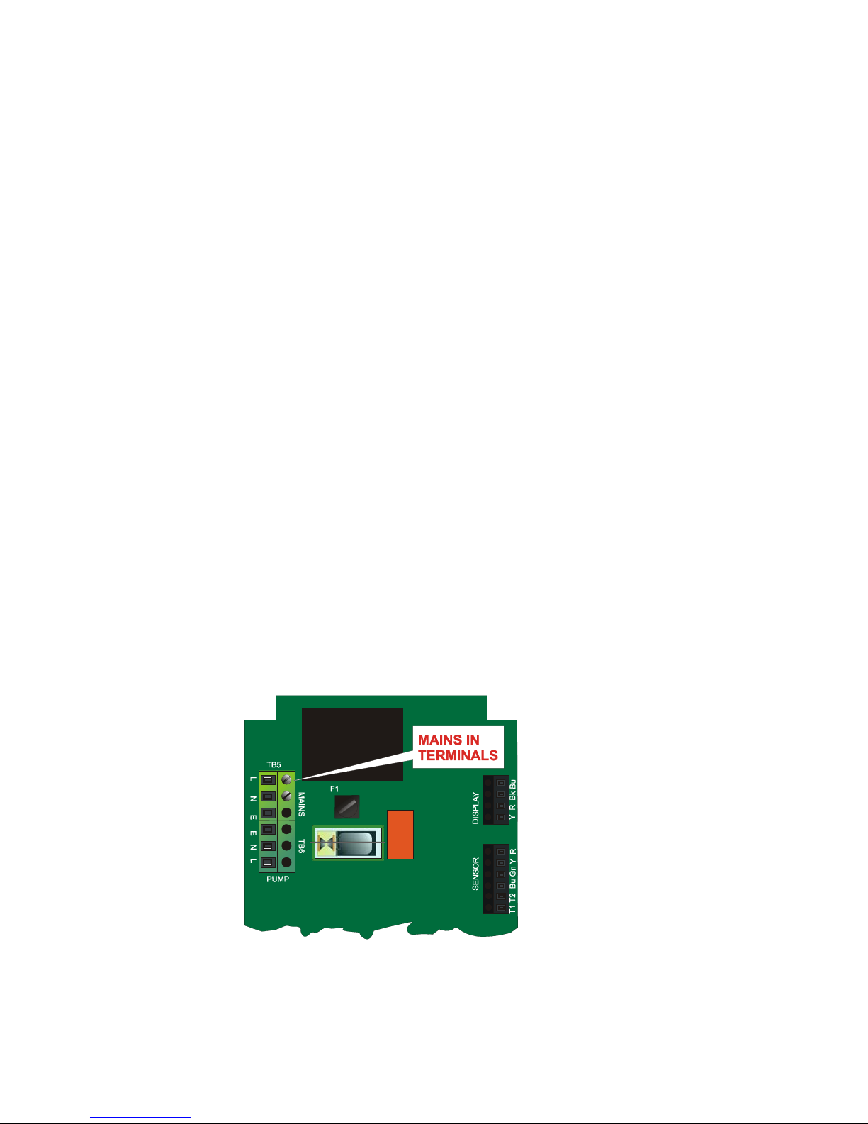
11) Refer to the Guide Sheet DIAGRAM C. The main electrical supply should come from either the
Distribution Board, fused or with MCB Type C rated 16 amps, thence via a separate Residual Current
Detector (RCD), or from a local switched fused spur with integral RCD. Remove the control unit lid and
identify the terminals within. The mains supply terminal block is marked L, N and E and is top left (facing) on
the control unit Printed Circuit Board.
Page 9
 Loading...