

Page 1
KLANG WERK
BLACET RESEARCH MODEL 2010
BALANCED MODULATOR
Users Manual
Blacet Research 15210 Orchard Rd Guerneville CA 95446
blacet@blacet.com http://www.blacet.com 707-869-9164
Contents Copyright.
Reproduction by any means including the Internet prohibited without permission.
This document contains proprietary and trade secret information of Blacet Research and is provided
as a service to the module owner. Any unauthorized duplication or transferral may violate trade secret laws.
Contents subject to change without notice.

Page 2
Introduction
Klang Werk is a high quality balanced (or “ring”) modulator with a number of built in features making it more
versatile than the usual synth module. It’s more like an effect box, although it is right at home in any modular
system. Klang Werk includes a voltage controlled sine to complex waveform carrier generator, a signal preamp, a
signal envelope follower, and an output mix control.
A balanced modulator takes two signals (“signal” and “carrier”) and multiplies them together, producing their sum
and difference frequencies. The original signals are removed from the output. The result is often used to produce bell
like clang tones. The world of the equally tempered scale seems to vanish, to be replaced by an alien sonic landscape
filled with moments of unearthly beauty and savage cacophony.
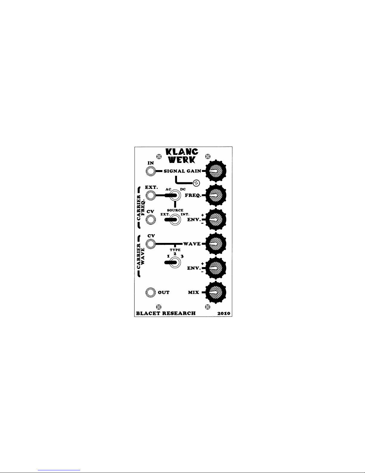
Front Panel Controls
Audio Input
0.5 to 10V
Carrier Input
Audio or voltage up to 10V
Source switch = EXT.
Signal Gain
0 to 10X
Internal Carrier Frequency
Control Voltage Input
0 to 10V
AC/DC Coupling
AC for Audio
DC for VCA use
External/Internal Carrier
Ext. for external carrier
Int. for internal carrier
Signal Level LED
Internal Carrier Frequency
0 to 1.6 KHz
+/- Signal Envelope Amount
Changes internal carrier
frequency
Internal Carrier Wave Morph
Sine wave to complex wave
Wave Morph Type
Sine wave to complex wave
+/- Signal Envelope Amount
Changes internal carrier
waveform
Mix
Blends original signal and
balanced modulator effect
Internal Carrier Wave Morph
Control Voltage Input
0 to 10V
Audio Output
Determined by Mix control
Page 3
Controls and Operation
Audio Input jack and Signal Gain control: At the heart of Klang Werk is a balanced modulator IC that will handle
+/-10V signals. For optimum signal to noise ratio with reasonable headroom, it is advisable to use a signal in the 510V range. The Signal Gain control can provide up to 10 times amplification for signals from keyboards, etc.
Signal Level LED: This will get brighter as the signal level increases. There is no overrange indication.
Carrier Input jack, AC/DC coupling switch, Int./Ext. Source switch: The carrier signal can be from the internal
source or be furnished externally and is selected by the Source switch. The external signal should be in the 0-10V
range. For audio signals, the AC/DC switch should be in AC. To use the Klang Werk as a VCA with the carrier
input being a control voltage, place the switch in the DC position.
Carrier Frequency CV jack, Freq. control, Env. +/- control: The internal carrier source is a sine wave VCO which can
be controlled by the Freq. knob, the voltage present at the CV jack and the amount of the signal envelope selected by
the Env. control. Note that with a - Env. setting it is possible to stop the VCO completely, depending on the setting
of the Freq. control.
Carrier Wave CV jack, Wave control, Type 1 2 3 switch, Env. +/- control: The sine wave from the internal VCO is
processed by a variable amount in this section. The amount of the effect from the pure sine wave is controlled by the
voltage at the CV jack, setting of the Wave control and the amount of the signal envelope selected by the Env. +/control. The Type switch changes the geometry of the internal processor to produce more pronounced wave changes
as the setting progresses from 1 to 3. Position 1 is a full wave rectifier circuit that gradually doubles the frequency of
the sine wave. Positions 2 and 3 provide non-linear waveform morphing with subtle filter and phasing effects.
External carrier signals are also processed through this section, with the exception of signals used with the AC/DC
switch in the DC position.
Audio Output jack, Mix control: The processed audio along with the original signal input is available at this jack.
The Mix control selects the amount of each signal present. Note that trimpot RT1 on the PCB can provide additional
output gain up to 3 times the basic level.
The output level is determined by the amplified input signal level times the carrier signal level, divided by ten and
multiplied by the setting of RT1 (1 to 3). The output cannot exceed 13.5V due to op amp restrictions.
For example, with a 1V signal input and 10x maximum gain=10V.
The internal carrier is typically 5V.
10 x 5 = 50
50/10 = 5
This is with RT1 at minimum. The signal can be boosted easily to 10V with RT1 at mid position.
Power Input jack J6: A source of regulated +/-15Vdc power must be supplied to this PCB jack to run Klang Werk.
Connections to this jack should be made only when the power supply is OFF and the connector must be positioned
correctly on the pins. An option is provided for using +/-18Vdc unregulated power ONLY when U2 and U3 are
present. As using the wrong supply can cause damage to the unit, please contact us if you have any questions!
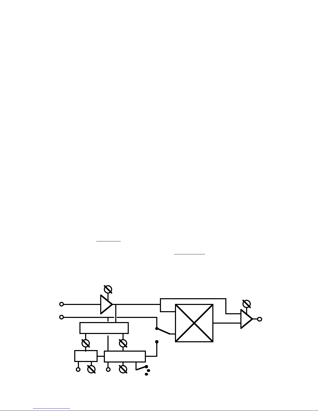
Block Diagram
OUT
VCO
WAVE MORPH
ENV. FOLLOWER
TYPE
SIGNAL
CARRIER
EXT/
INT
CV
CV
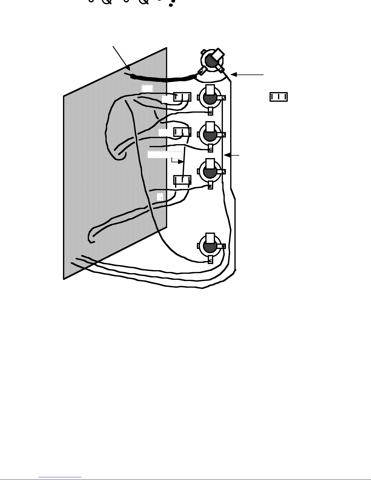
Page 4
J1J2J3J4J5
S1S2S312
3
Switch Pins
8.0”
8.5” strip 1.6
2.5”
3.5”
4.5”
3.3”
shielded*
3.8”
3.4 strip 1.8”
2.9”5”2.9”5”5”
6.7”
strip 0.5”
2.3”
*shield not connected this end
Calibration
The four on-board trim pots need to be adjusted for optimum performance. All these adjustments should be done
with the MIX control FCW.
RT1 affects the output gain and may be adjusted from unity gain (FCCW) to 3X gain (FCW). This feature allows
you to match signal levels to other equipment.
RT2 sets the minimum frequency frequency of the VCO. Set the FREQ. control FCCW and the freq. ENV control to
mid position. Turn RT2 CW until the VCO is running at about 5 Hz. The output signal will sound as if it has a fast
vibrato at this frequency. This is not a critical adjustment.
RT3 nulls the signal feedthru. With the SOURCE switch in the EXT. position (and no EXT. input or ENV amount),
insert a signal from a keyboard or other source into the IN jack. Turn up your amp and listen for this signal. Rotate
RT3 for minimum level.
RT4 nulls the carrier feedthru. This is probably the most important adjustment on the module. Since the carrier
signal is always present, an effective null is important to avoid hearing the carrier in the output, when the input
TYPE
CV
CV

Page 5
signal is not present. The optimum setting for the trimmer is affected a bit by the SIGNAL GAIN and MIX controls,
so you should find their most typical settings , based upon your system levels, before you set the trimmer.
To set RT4, turn the FREQ control FCW and turn up your amp. As you adjust RT4, you will hear the carrier signal
faintly. Adjust RT4 for the minimum level of this signal.
Repair
If you encounter problems that you can’t solve, contact us, preferably via e-mail with a description of the problem.
We can then help you get your module working.
Warranty
The parts contained in this unit have been carefully selected and tested. They are guaranteed for 90 days from the
date of purchase. If you believe that you have a defective part (or if you have a part missing), contact us so we can
provide you with a replacement or repair.
 Loading...