

Page 1

Global SVQQPSU SFSWJDFT (GSS) Knowledge Services
KLA-Tencor Confidential—Restricted Distribution
KT Automation User Guide
9022549‐000
AB
Page 2

KT Automation User Guide
Page Intentionally Blank
9022549-000 / AB
KLA-Tencor Confidential - Restricted Distribution
Page 3

KT Automation User Guide
is preliminary document is not complete. This document contains significant
omissions and inaccuracies. GSS Technical Publications distributes this
preliminary draft for review purposes only. Customers and KLA- Customer
Service Engineers should not use this document while installing, servicing, or
using the KT Automation System. Any input regarding the accuracy of the
content of this document is welcome and appreciated.
KLA-Tencor Corporation
One Technology Drive,
Milpitas, CA. 95035
KLA-Tencor Technical Publications
KLA-Tencor Confidential - Restricted Distribution
Page 4

Copyright
Copyright © 2016-2017 by KLA-Tencor. All rights reserved worldwide. No part of this publication may be
reproduced, modified, transmitted, transcribed, stored in retrieval systems, or translated into any human or computer
language, in any form or by any means, electronic, mechanical, magnetic, chemical, manual, or otherwise, without the
express written permission of KLA-Tencor, One Technology Drive, Milpitas, California 95035. KLA-Tencor may
revise this document at any time without notice.
Trademarks
KT Automation™ System, SensArray® Temperature Wafers, and Automation Metrology™ Wafers are trademarks of
KLA-Tencor Corporation. KLA-Tencor
Corporation. All other brand and product names may be trademarks of their respective companies.
®
and the KLA-Tencor logo are registered trademarks of the KLA-Tencor
Reprint Acknowledgements
This document contains excerpts from the following SEMI® Standards and/or Safety Guidelines: SEMI S1-0708E,
“Safety Guidelines for Equipment Safety Labels,” and SEMI S2-0709, “Environmental Health, and Safety Guidelines
for Semiconductor Manufacturing Equipment,” Copyright © Semiconductor Equipment and Materials International
2009. All Rights Reserved. Used by Permission. SEMI is a registered trademark of Semiconductor Equipment and
Materials International. www.semi.org
Original Instructions.
Send any comments to:
GSS.ECMSAdmin@kla-tencor.com
9022549-000 / AB Printed in Milpitas
KLA-Tencor Confidential - Restricted Distribution
Page 5

Preface
. 1.Introduction
1.1 KT Automation System Overview . . . . . . . . . . . . . . . . . . . . . . . . . . . . . . . . . . . . . . . . . . . . . 1-1
1.2 KT Automation System Operation. . . . . . . . . . . . . . . . . . . . . . . . . . . . . . . . . . . . . . . . . . . . . 1-2
1.3 KT Automation Missions . . . . . . . . . . . . . . . . . . . . . . . . . . . . . . . . . . . . . . . . . . . . . . . . . . . . 1-3
1.4 Regulatory Compliance Statements . . . . . . . . . . . . . . . . . . . . . . . . . . . . . . . . . . . . . . . . . . . . 1-4
Table of Contents
Preface . . . . . . . . . . . . . . . . . . . . . . . . . . . . . . . . . . . . . . . . . . . . . . . . . . . . . . . . . . 1
1.4.1 Prohibitions on Modifications. . . . . . . . . . . . . . . . . . . . . . . . . . . . . . . . . . 1-4
1.4.2 Class A Digital Device . . . . . . . . . . . . . . . . . . . . . . . . . . . . . . . . . . . . . . . 1-4
1.4.3 Special Accessory Installation: Manual Use Laptop/FOUP cable . . . . . . 1-4
. 2.KT Automation System Hardware Components
2.1 KT Automation Station . . . . . . . . . . . . . . . . . . . . . . . . . . . . . . . . . . . . . . . . . . . . . . . . . . . . . 2-5
2.1.1 KT Automation Station Function . . . . . . . . . . . . . . . . . . . . . . . . . . . . . . . 2-5
2.1.2 KT Automation Station Indicator Panel LEDs . . . . . . . . . . . . . . . . . . . . . 2-6
2.1.3 KT Automation Station Indicator Panel Manual/Auto Button . . . . . . . . . 2-7
2.2 KT Automation FOUP . . . . . . . . . . . . . . . . . . . . . . . . . . . . . . . . . . . . . . . . . . . . . . . . . . . . . . 2-7
2.2.1 KT Automation FOUP Function. . . . . . . . . . . . . . . . . . . . . . . . . . . . . . . . 2-7
2.2.2 KT Automation FOUP Indicators and Controls . . . . . . . . . . . . . . . . . . . . 2-8
2.2.3 KT Automation FOUP Data Storage and Transfer . . . . . . . . . . . . . . . . . . 2-9
2.2.4 KT Automation FOUP Battery . . . . . . . . . . . . . . . . . . . . . . . . . . . . . . . . . 2-9
2.2.5 Option: Emulating Occupied KT Automation FOUP Slots . . . . . . . . . . 2-10
9022549-000/AB KLA-Tencor Confidential - Restricted Distribution v
Page 6

TABLE OF CONTENTS
. 3.KT Automation Web UI
3.1 Logging In . . . . . . . . . . . . . . . . . . . . . . . . . . . . . . . . . . . . . . . . . . . . . . . . . . . . . . . . . . . . . . .3-11
3.2 Logging Out. . . . . . . . . . . . . . . . . . . . . . . . . . . . . . . . . . . . . . . . . . . . . . . . . . . . . . . . . . . . . .3-11
3.3 KT Automation Home Page . . . . . . . . . . . . . . . . . . . . . . . . . . . . . . . . . . . . . . . . . . . . . . . . .3-12
3.3.1 Equipment Coverage and Usage . . . . . . . . . . . . . . . . . . . . . . . . . . . . . . .3-13
3.3.2 Tool Mission Alarms . . . . . . . . . . . . . . . . . . . . . . . . . . . . . . . . . . . . . . . .3-14
3.3.3 Connected FOUPs . . . . . . . . . . . . . . . . . . . . . . . . . . . . . . . . . . . . . . . . . .3-15
3.4 Tools Page . . . . . . . . . . . . . . . . . . . . . . . . . . . . . . . . . . . . . . . . . . . . . . . . . . . . . . . . . . . . . . .3-16
3.5 Setup Page . . . . . . . . . . . . . . . . . . . . . . . . . . . . . . . . . . . . . . . . . . . . . . . . . . . . . . . . . . . . . . .3-17
3.5.1 Edit or Add Tool. . . . . . . . . . . . . . . . . . . . . . . . . . . . . . . . . . . . . . . . . . . .3-17
3.5.2 Edit or Add Tool Type . . . . . . . . . . . . . . . . . . . . . . . . . . . . . . . . . . . . . . .3-18
3.5.3 Edit or Add Handler Type . . . . . . . . . . . . . . . . . . . . . . . . . . . . . . . . . . . .3-23
3.5.4 Edit or Add Wafer Sequence . . . . . . . . . . . . . . . . . . . . . . . . . . . . . . . . . .3-24
3.6 History Page . . . . . . . . . . . . . . . . . . . . . . . . . . . . . . . . . . . . . . . . . . . . . . . . . . . . . . . . . . . . .3-25
3.7 Administration Page . . . . . . . . . . . . . . . . . . . . . . . . . . . . . . . . . . . . . . . . . . . . . . . . . . . . . . .3-25
PRELIMINARY
3.8 Automation Metrology Wafer Functions. . . . . . . . . . . . . . . . . . . . . . . . . . . . . . . . . . . . . . . .3-26
3.8.1 Edit or Add an Automation Metrology Wafer Mission Recipe . . . . . . . .3-26
3.8.2 Define and Execute an Automation Metrology Wafer User Mission. . . .3-29
Glossary
Revision History
vi KLA-Tencor Confidential - Restricted Distribution KT Automation User Guide
Page 7

Manual Purpose
This User Guide describes:
• Hardware components of the KT Automation
instrumented test wafers
• Setting up the system for automatic missions
• Managing inventory
• Controlling the KT Automation System
• Launching user missions using SensArray® Temperature Wafers and
Automation Metrology™ Wafers
Preface
™
System for KLA-Tencor
Manual Structure
This manual consists of this preface, 4 sections, and a glossary. Each section is
briefly described below:
Preface
Introduces the manual.
Section 1: Introduction
This section provides an introduction to the KT Automation System.
Section 2: KT Automation System Hardware Components
This section describes the functions and controls of the KT Automation System
hardware components.
Section 3: KT Automation System Web UI
This section describes how to use the Web UI of the KT Automation System.
Glossary
Defines abbreviations and terms used in the manual.
9022549-000/AB KLA-Tencor Confidential - Restricted Distribution 1
Page 8
Preface
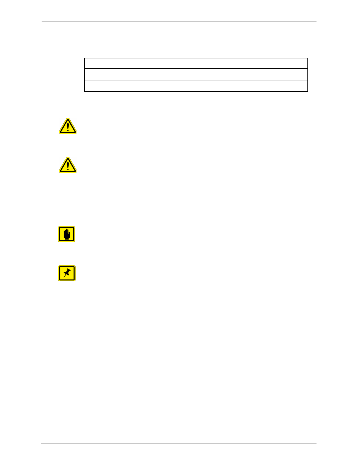
WARNING
CAUTION
IMPORTANT
NOTE
Reference Documentation
The following table specifies documents referenced in this manual.
Document Number Title
9022547-000 CPG KT Automation System Safety Manual
9022552-000 KT Automation System GEM/SECS Reference Manual
Conventions Used in this Manual
Indicates danger to personnel.
Includes instructions needed to prevent any damage.
Indicates danger to Equipment.
Includes instructions needed to prevent any damage.
When either of the above symbols appear in this manual, follow the advice
given. Failure to do so may endanger yourself or others, and can result in
damage to the Equipment.
Indicates there is possibility for a failure.
Includes the instruction needed to prevent the failure.
Indicates there is additional information connected with the current subject.
Includes that information.
Special terms
Special terms (dialog box names, button names and any other unique term)
are in bold, as demonstrated in the example below:
File menu, Start button.
Hyperlinks
Hyperlinks to references in this document appear in blue (on screen).
Hyperlinks to web sites, or external documentation, are blue and underlined.
2 KLA-Tencor Confidential - Restricted Distribution KT Automation User Guide
Page 9

1.
1.1 KT Automation System Overview
The KT Automation System provided by KLA-Tencor automates the use of
instrumented wafers in a semiconductor wafer fab. The KT Automation System
is used with SensArray temperature wafers and Automation Metrology motion
analysis wafers to enable real-time measurement and monitoring of
parameters that are critical to fab yield and productivity.
The KT Automation hardware consists of the following components:
• Battery-powered, instrumented wafers that perform the actual
measurements and reside in Automation FOUPs; examples are SensArray
Temperature Wafers and Automation Metrology Wafers (to measure motion
and humidity)
Introduction
• Battery-powered Automation FOUPs to transport and store instrumented
wafers, and to provide wafer charging and data communications (see
Section 2.2 for information about KT Automation FOUPs)
• KT Automation Stations that charge Automation FOUPs and provide the
communication between the FOUP and the fab host (see Section 2.1 for
information about KT Automation Stations)
• KT Automation Controller to control the system
9022549-000/AB KLA-Tencor Confidential - Restricted Distribution 1
Page 10
1. Introduction KT Automation System Operation
1.2 KT Automation System Operation
The KT Automation System provided by KLA-Tencor is used to deploy and
manage instrumented wafers
measurement and monitoring of parameters that are critical to fab yield and
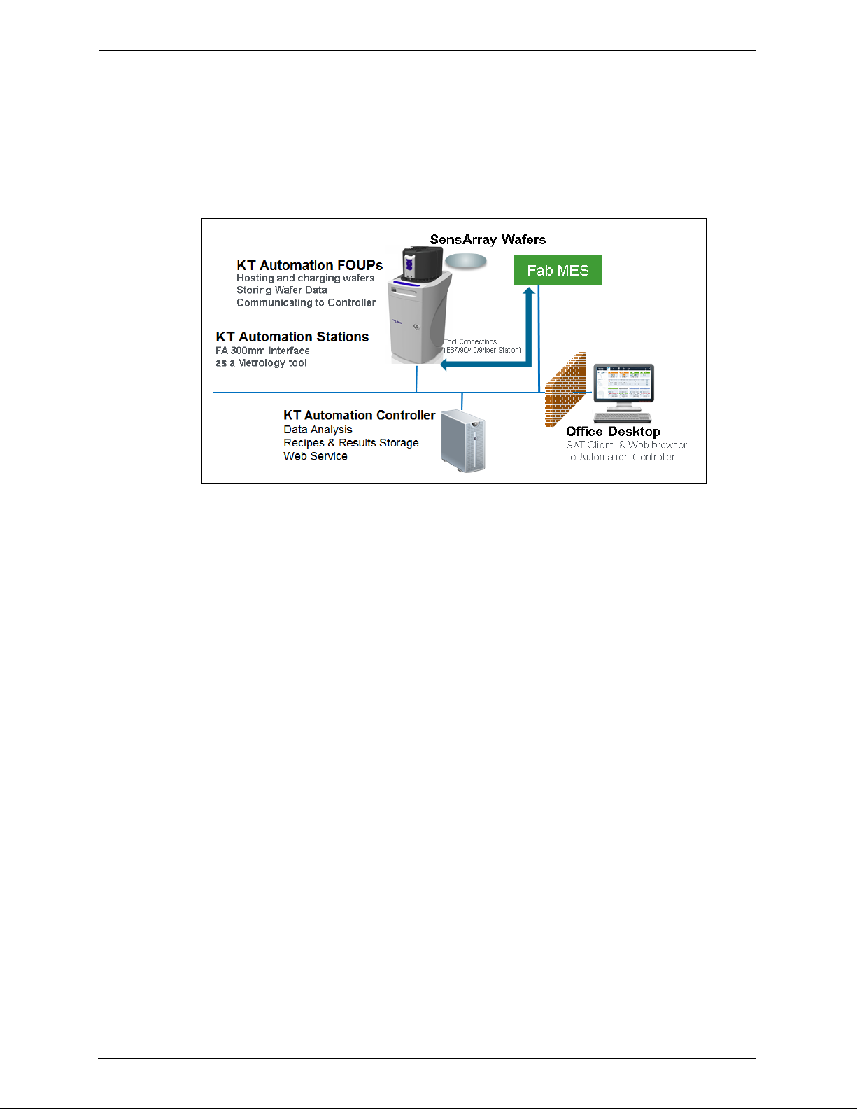
productivity. Operation is completely automated (see Figure 1-1).
Figure 1-1: KT Automation System Topology
in a
semiconductor wafer fab to enable real-time
Measurement “missions” are executed automatically under control of the fab
manufacturing execution system (MES). The instrumented wafers are
transported by the fab OHT and automated material handling system (AMHS)
to and from the tool under test. Tests are executed on process tools without
removing them from full automated mode. Mission results are communicated
directly to the MES, plus results can be automatically available to engineers
inside and outside the fab through a web-based GUI and desktop analysis
software system.
Measurements are easy to accomplish without removing the process tools from
production use and without manual handling or recipe execution in the fab.
This enables KT metrology wafers to be used for in-line monitoring of process
and mechanical system parameters, preventing excursions that can cause yield
loss, and improving tool matching performance.
Examples of instrumented metrology wafers from KT that are supported by this
system are: the SensArray EtchTemp Wafer for monitoring etch temperature;
and the KT Automation Metrology Wafer for monitoring AMHS FOUP and
equipment front end wafer handling.
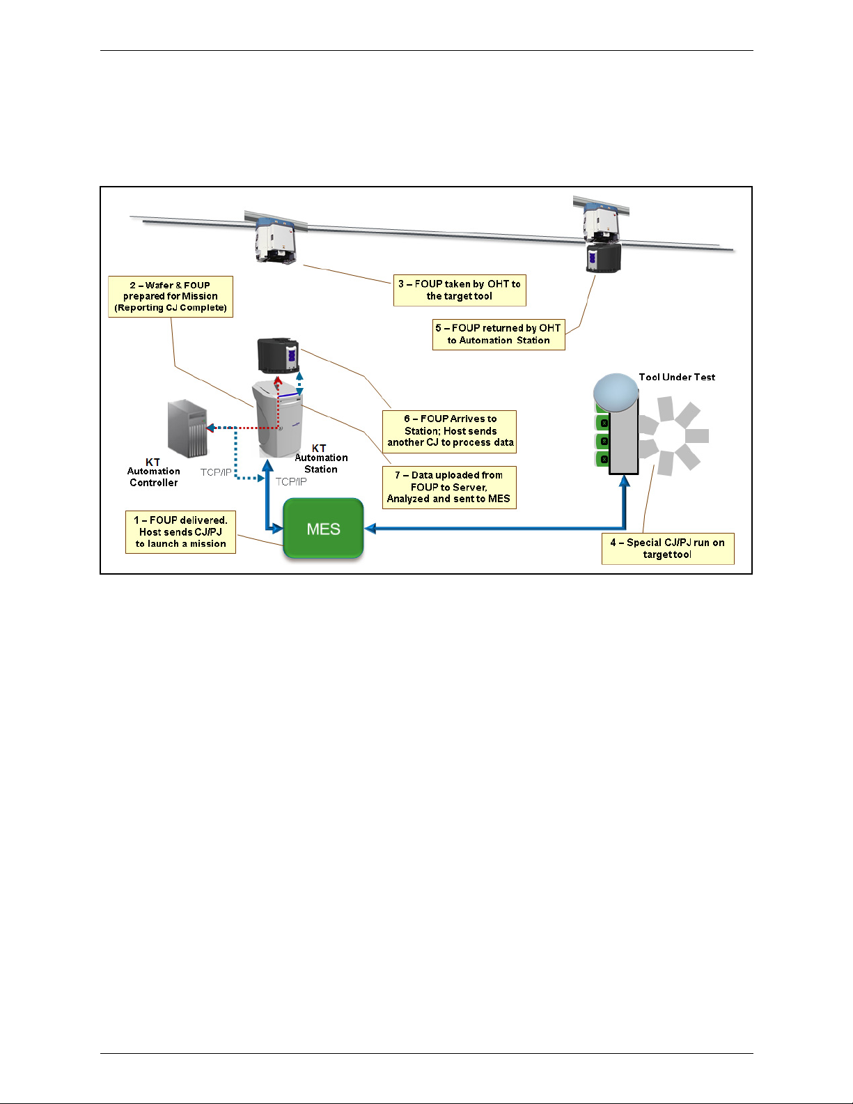
To create and launch a new mission (see Figure 1-2), the MES system sends
the instrumented wafer(s) in a KT Automation FOUP to the KT Automation
Station (1). The MES communicates with the KT Automation Station to initiate
the mission with a Control Job/Process Job (CJ/PC). If the correct wafers for
the mission are present in the FOUP with sufficient charge, the CJ/PJ is
completed (2). The FOUP is transported to the target tool under test by the
standard fab AMHS (3). The MES host system initiates the correct test recipe
on the target tool in full auto mode. When the test is complete, the Automation
FOUP is returned to the Automation Station (5). When the Automation FOUP
2 KLA-Tencor Confidential - Restricted Distribution KT Automation User Guide
Page 11
1. Introduction KT Automation Missions
arrives at the Automation Station, the host executes another CJ/PJ to process
the data (6). The mission results are uploaded to the KT Automation Controller
and the Go/No Go results are reported to the host from the Station, per the
metrology recipe in effect (7).
Figure 1-2: KT Automation System Mission Sequence
1.3 KT Automation Missions
There are 3 ways to launch and control KT Automation missions:
1. Automatic missions: controlled by fab MES via Factory Automation (as
described above); results are reported back to the MES (see
9022552-000, KT Automation System GEM/SECS Reference
Manual)
2. User missions: initiated by an operator via the KT Automation Web UI;
the Automation FOUP is carried manually to the target tool and back to the
station
3. Manual missions: initiated through the SA Tools software installed on a
laptop that is directly connected to the Automation FOUP and provides all
the required parameters for starting a mission; the Automation FOUP is
carried manually to the target tool and the mission is manually executed
on that tool
9022549-000/AB KLA-Tencor Confidential - Restricted Distribution 3
Page 12

1. Introduction Regulatory Compliance Statements
1.4 Regulatory Compliance Statements
1.4.1 Prohibitions on Modifications
Changes or modifications not expressly approved by KLA Tencor could void the
user's authority to operate the equipment.
1.4.2 Class A Digital Device
Note: This equipment has been tested and found to comply with the limits for
a Class A digital device, pursuant to part 15 of the FCC Rules. These limits are
designed to provide reasonable protection against harmful interference when
the equipment is operated in a commercial environment. This equipment
generates, uses, and can radiate radio frequency energy and, if not installed
and used in accordance with the instruction manual, may cause harmful
interference to radio communications. Operation of this equipment in a
residential area is likely to cause harmful interference in which case the user
will be required to correct the interference at his own expense.
1.4.3 Special Accessory Installation: Manual Use Laptop/FOUP cable
1. Verify SensArray Tools software is installed before connecting cable to
ensure appropriate communication settings.
2. Connect power supply to barrel connector in middle of manual use case
cable.
3. Connect manual use case RJ (Ethernet) connector to Ethernet port on
laptop.
4. Connect manual use case cable to FOUP magnetic connector on the back of
the FOUP to the left of the power switch. The factory provided ferrite must
be installed on the magnetic connector side of the manual use case cable.
4 KLA-Tencor Confidential - Restricted Distribution KT Automation User Guide
Page 13

2.
NOTE
KT Automation System Hardware
2.1 KT Automation Station
2.1.1 KT Automation Station Function
The KT Automation Station communicates with the KT Automation FOUP to
start missions and to extract the results after the missions are completed. The
KT Automation Station also recharges the KT Automation FOUP between
missions.
Figure 2-1 shows the KT Automation Station (including the optional signal
tower), with and without a KT Automation FOUP loaded on the station.
Components
Figure 2-1: KT Automation Station
If your system uses the optional signal tower, the signal tower is installed and
configured at the time the rest of the system is installed.
9022549-000/AB KLA-Tencor Confidential - Restricted Distribution 5
Page 14
2. KT Automation System Hardware Components KT Automation Station
2.1.2 KT Automation Station Indicator Panel LEDs
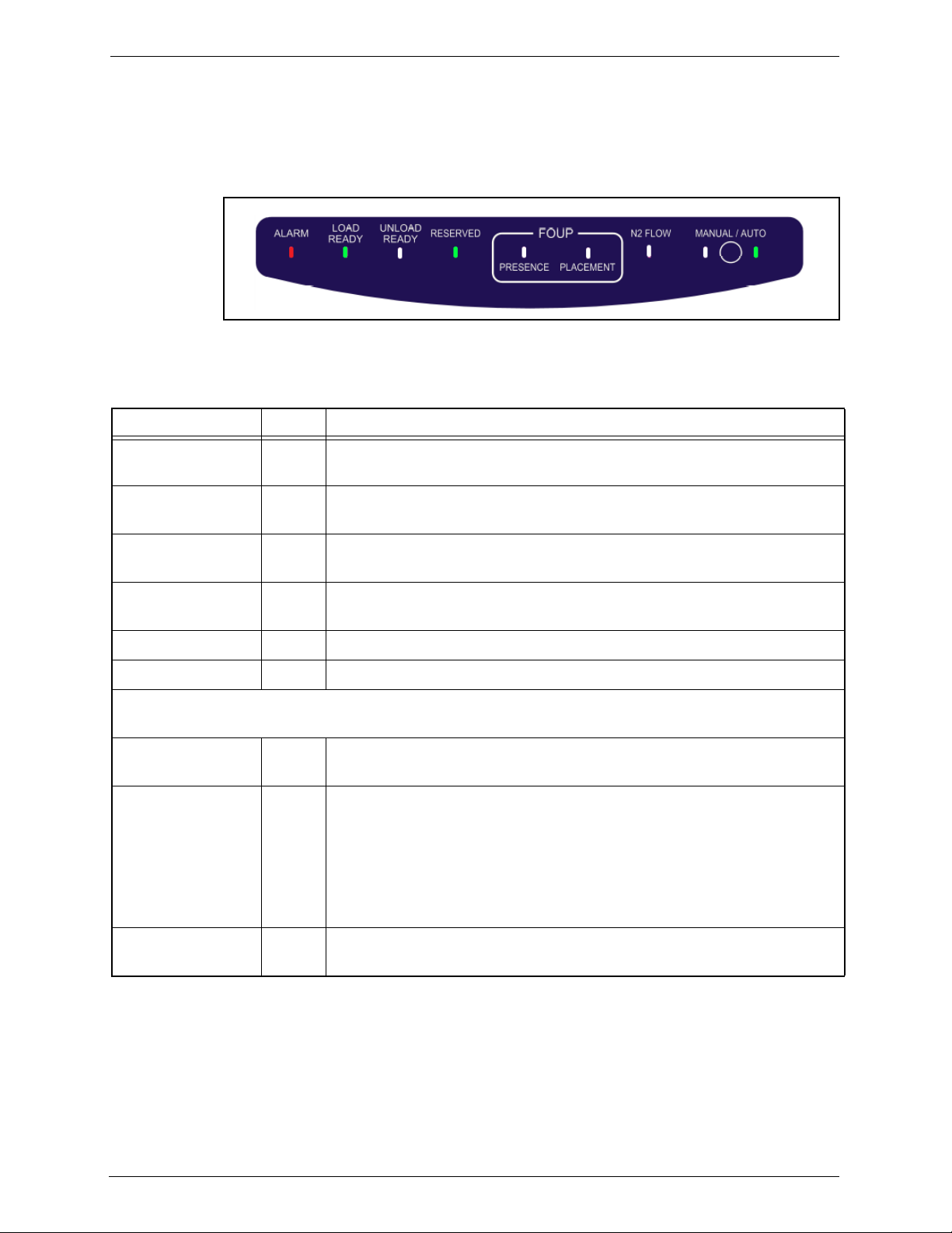
The indicator panel at the front of the top cover (see Figure 2-2) contains all
the Automation Station LEDs, as well as the Manual/Auto control button.
Figure 2-2: KT Automation Station Indicator Panel
Table 2-1: KT Automation Station Indicator Panel LEDs
LED Name Color Description
ALARM Red Indicates a critical error (for example, application has stopped working)
that requires the operator to recover the Automation Station
LOAD READY Green Indicates the Automation Station is ready to receive a FOUP (there is
currently no FOUP on the Automation Station)
UNLOAD READY Green Indicates the FOUP can be unloaded from the Automation Station
(there is currently a FOUP loaded on the Automation Station)
RESERVED Green Indicates the Automation Station is reserved by the fab Host for a
mission
FOUP PRESENCE Green Indicates a FOUP is present on the Automation Station
FOUP PLACEMENT Green Indicates a FOUP is fully placed on the Automation Station
Important:
When a FOUP is seated properly, both the FOUP PRESENCE and the FOUP PLACEMENT LEDs are on.
N2 FLOW Indicates N2 is flowing from the Automation Station to the FOUP (in
systems that include the N2 option)
MANUAL Blinking MANUAL LED
Indicates the Automation Station is in the process of initializing and is
not yet ready for use
Steady MANUAL LED
Indicates the Automation Station is in Manual mode (user can manually
place or remove a FOUP)
AUTO Green Indicates the Automation Station is in Auto mode (controlled by the fab
Host and the OHT delivery system)
6 KLA-Tencor Confidential - Restricted Distribution KT Automation User Guide
Page 15

2. KT Automation System Hardware Components KT Automation FOUP
NOTE
The KT Automation FOUP configuration
must be updated when:
* The CID pill is written or replaced, or
* The network configuration or server
IP address has changed.
2.1.3 KT Automation Station Indicator Panel Manual/Auto Button
The Manual/Auto control button is located between the MANUAL and the AUTO
LEDs on the KT Automation Station Indicator Panel (see Figure 2-2).
The button has two functions:
1. Toggles between Auto mode and Manual mode
Press and hold the Manual/Auto control button for 5 seconds to toggle the
Automation Station between Auto mode and Manual mode, indicated by
the AUTO and MANUAL LEDs.
2. Operates the Automation Station (when the Automation station is in
Manual mode)
• When the FOUP is present on the Automation Station, press and release
the button to unclamp the FOUP and switch it to the UNLOAD READY
state (UNLOAD READY LED is green), which allows you to pick it up
manually.
• When the Automation Station is in the LOAD READY state (LOAD READY
LED is green):
• Manually place the FOUP on the Automation Station.
• Press and release the Manual/Auto control button to lock the FOUP
and connect it to the Automation Station.
2.2 KT Automation FOUP
2.2.1 KT Automation FOUP Function
The KT Automation FOUP transports the instrumented wafer to the equipment
during missions. It also charges the wafer, stores the wafer data, and
communicates the wafer data to the Automation Controller.
Figure 2-3: KT Automation FOUP
9022549-000/AB KLA-Tencor Confidential - Restricted Distribution 7
Page 16

2. KT Automation System Hardware Components KT Automation FOUP
2.2.2 KT Automation FOUP Indicators and Controls
All FOUP indicators and controls are on the rear of the KT Automation FOUP
(see Figure 2-4).
Figure 2-4: KT Automation FOUP Indicators and Controls
Table 2-2: KT Automation FOUP Indicators and Controls
Control or Indicator Color Comments
Wafer Charging LED Green Blinks when the applicable Wafer is charging
Steady when the applicable Wafer is present but not charging
(Wafer is fully charged)
Orange Steady when the applicable Wafer is absent
FOUP Charging LED Green Blinks when the FOUP is charging
Steady when the FOUP is powered On and at the Station but not
charging (FOUP is fully charged)
Orange Steady when the FOUP is powered On but is not at the Station
Reset button n/a To press the Reset button, insert a thin stylus or pen tip into the
hole
Important: Reset the FOUP only if it is an error state.
Manual power/
communication connector
ON/OFF button n/a To power down the FOUP, press and hold the ON/OFF button
n/a Used to connect a laptop to the FOUP in order to perform
manual missions, or provide power to a FOUP that has not been
at the Station for a long time
until the FOUP Charging LED turns off
8 KLA-Tencor Confidential - Restricted Distribution KT Automation User Guide
Page 17

2. KT Automation System Hardware Components KT Automation FOUP
NOTE
NOTE
2.2.3 KT Automation FOUP Data Storage and Transfer
• When the Wafer is back in the Automation FOUP, it automatically transmits
the data it collected during the mission to the Automation FOUP.
• When the Automation FOUP is placed on the Automation Station, the
Automation FOUP automatically transmits the data to the Automation
Controller to be stored in the centralized database.
• An Automation FOUP can store up to 10 hours of data.
2.2.4 KT Automation FOUP Battery
• When an Automation FOUP’s charge level goes down to 35%, an alarm is
sent to the host.
• The Automation FOUP goes into power-save mode:
• When the charge level goes down to 20%
• If it is not on a mission and has not been charged for 30 minutes
• When in power-save mode, the Automation FOUP can maintain its charge
for 6 months.
• To charge an Automation FOUP, place it on the FOUP Station and make sure
it is clamped (not in LOAD READY state), or use the manual
power/communication cable to connect it to a laptop.
If the Automation FOUP was powered off, placing it on the Automation Station
and clamping it will power it on automatically.
• When powered off, the Automation FOUP can maintain its charge for 12
months.
If the Automation FOUP loses its charge completely, please ask your KT service
representative to change the battery.
9022549-000/AB KLA-Tencor Confidential - Restricted Distribution 9
Page 18

2. KT Automation System Hardware Components KT Automation FOUP
2.2.5 Option: Emulating Occupied KT Automation FOUP Slots
An available KT Automation FOUP option is a set of emulation fins for slots that
contain any electronics boxes. The fins cause load port wafer mappers to
identify those slots as occupied.
Figure 2-5: KT Automation System Topology
10 KLA-Tencor Confidential - Restricted Distribution KT Automation User Guide
Page 19

3.
3.1 Logging In
1. At the KT Automation login page, select your role (in this example,
Administrator is selected).
2. Enter your password.
3. Click Start to log in and go to the Home page (see Section 3.3).
KT Automation Web UI
3.2 Logging Out
1. From any page in the KT Automation Web UI, click Logout.
The display returns to the KT Automation login page.
9022549-000/AB KLA-Tencor Confidential - Restricted Distribution 11
Page 20

3. KT Automation Web UI KT Automation Home Page
3.3 KT Automation Home Page
The Home page summarizes the current status of all KT Automation System
components, usage, and recent mission alerts. It is the first page that you see
after you log on.
1. To return to the Home page from any other KT Automation page, click
Home.
12 KLA-Tencor Confidential - Restricted Distribution KT Automation User Guide
Page 21

3. KT Automation Web UI KT Automation Home Page
3.3.1 Equipment Coverage and Usage
The Equipment Coverage & Usage area allows you to view information
about the Tools, KT Automation FOUPs, KT Wafers, and KT Automation
Stations in the system.
The color of the header for each equipment type shows the extent of usage:
• Green:High usage (>80%)
• Orange:Low usage
• Red:Not used
1. To select the time period for which you want to see coverage and usage
information, select the time period from the drop-down list in the top
right-hand corner.
9022549-000/AB KLA-Tencor Confidential - Restricted Distribution 13
Page 22

3. KT Automation Web UI KT Automation Home Page
2. To view the statistics for the equipment type, hover the cursor over the
image.
Equipment Statistics Provided
Tools
KT Automation
FOUPs
KT Automation
Stations
KT Wafers
• How many configured
• How many online (as number)
• How many online (as percentage)
• How many hours purchased
• How many hours used (as number)
• How many hours used (as percentage)
3.3.2 Tool Mission Alarms
The Tool Mission Alarms area lists error messages and alerts received during
recent missions.
14 KLA-Tencor Confidential - Restricted Distribution KT Automation User Guide
Page 23

3. KT Automation Web UI KT Automation Home Page
3.3.3 Connected FOUPs
The Connected FOUPs area displays all KT Automation FOUPs (carriers) in
the system and their statuses.
For each FOUP, the following information is displayed:
1. Carrier ID
2. Carrier status
3. Wafer IDs
4. Battery level of KT Automation FOUP
9022549-000/AB KLA-Tencor Confidential - Restricted Distribution 15
Page 24

3. KT Automation Web UI Tools Page
NOTE
3.4 Tools Page
The Tools page displays information about all the tools that were set up in the
system (as described in Section 3.5.1 through Section 3.5.4).
To v ie w t h e Tools page, click Tools.
• shows that the last mission that ran on this tool was successful
• shows that the last mission that ran on this tool indicated a problem
1. You can group tools by:
•Tool Type
•Tool Location
• Mission Time (mission run date and time)
16 KLA-Tencor Confidential - Restricted Distribution KT Automation User Guide
Page 25

3. KT Automation Web UI Setup Page
IMPORTANT
IMPORTANT
3.5 Setup Page
Use the Setup page to add new or edit existing tools and mission recipes.
Mission recipes are added or edited for Automation Metrology Wafers only. See
Section 3.8.1 for details of adding or editing recipes.
1. To view the Setup page, click Setup.
3.5.1 Edit or Add Tool
Before you can add a new tool, the applicable tool type and handler type must
have been defined in the system (see Section 3.5.2 and Section 3.5.3).
1. In the Setup page, make sure Tools is selected (the default selection
when the Setup page opens).
2. Continue as follows:
• To edit an existing tool, click the Edit icon for the tool.
• To add a new tool, click + New Tool.
In either case, the Edit Tool window opens.
9022549-000/AB KLA-Tencor Confidential - Restricted Distribution 17
Page 26

3. KT Automation Web UI Setup Page
NOTE
3
3. In the Edit Tool window, enter or select a value for every field.
If you are editing an existing tool, enter or select new values only for those
fields that you need to update.
4. Click Save to save the values and close the Edit Tool window.
3.5.2 Edit or Add Tool Type
1. In the Setup page, click Tool Type.
2. Continue as follows:
• To edit an existing tool type, click the Edit icon for the tool type.
• To add a new tool, click + New Tool Type.
In either case, the Tool Type Edit window opens.
18 KLA-Tencor Confidential - Restricted Distribution KT Automation User Guide
Page 27

3. KT Automation Web UI Setup Page
NOTE
IMPORTANT
If you are editing an existing tool type, enter or select new values only for
those fields that you need to update.
3. In the Tool Type Edit window, type a Tool Type Name.
Use an informative name that includes information that will be important for
operators to know about the tool.
4. Select the Tool Type Recipe.
5. Continue as follows:
If you want to... Then continue with...
Create a new Tool Type Sequence
Modify an existing Tool Type Sequence
step 6
step 11
9022549-000/AB KLA-Tencor Confidential - Restricted Distribution 19
Page 28

3. KT Automation Web UI Setup Page
NOTE
6. To create a new Tool Type Sequence from scratch, click +New.
Each location that wafers visit within a tool is called a tool station.
7. From the list of available stations, select the first station in the sequence.
8. Continue clicking +New and selecting stations until you have selected
every station in the sequence.
9. For the last station in the sequence (in this example, FOUP), click Finish
here to select that station and remove the option to select from the other
stations.
10. Click Save to save the new tool type and close the Tool Type Edit
window.
20 KLA-Tencor Confidential - Restricted Distribution KT Automation User Guide
Page 29

3. KT Automation Web UI Setup Page
11. You can modify an existing Tool Type Sequence in any of the following
ways:
• Change the station where the sequence finishes
• Delete a station from the sequence or replace it with a different station
• Add another station to the sequence
12. To change the station where the sequence finishes:
• Click to deselect the station.
Every station in the sequence then displays the option to select it.
•Click Finish here to select the new station where the sequence
finishes.
9022549-000/AB KLA-Tencor Confidential - Restricted Distribution 21
Page 30

3. KT Automation Web UI Setup Page
NOTE
13. To delete a station from the sequence or replace it with a different station:
• Click for that station.
•Click Replace station.
• To delete the station, click Delete station.
• To replace the station, click the station from the list of available station.
The list contains those stations that are set up in the KT Automation System
but are not currently used in this Tool Type Sequence.
14. When you have made all the required changes to the Tool Type
Sequence, click Save to save the changes and close the Tool Type Edit
window.
22 KLA-Tencor Confidential - Restricted Distribution KT Automation User Guide
Page 31

3. KT Automation Web UI Setup Page
NOTE
IMPORTANT
3.5.3 Edit or Add Handler Type
The only parameter that is entered for a Handler Type is the Name.
1. In the Setup page, click Handler Types.
2. Continue as follows:
• To edit an existing handler type, click the Edit icon for the handler type.
• To add a new handler type, click + New.
3. Type the Name for the handler type.
Use an informative name that shows the robot type, the number of load ports,
and any other information that will be important for operators to know about
the handler type.
4. Click to save.
9022549-000/AB KLA-Tencor Confidential - Restricted Distribution 23
Page 32

3. KT Automation Web UI Setup Page
NOTE
IMPORTANT
3.5.4 Edit or Add Wafer Sequence
The only parameter that is entered for a Chamber or Station is the Name.
1. In the Setup page, click Wafer Sequence.
2. Continue as follows:
• To edit an existing chamber or station, click the Edit icon for the
chamber or station.
• To add a new chamber, click + New Chamber.
• To add a new location, click + New Station.
3. Type the Name for the chamber or station.
Use an informative name that includes information that will be important for
operators to know about the chamber or station.
4. Click to save.
24 KLA-Tencor Confidential - Restricted Distribution KT Automation User Guide
Page 33

3. KT Automation Web UI History Page
NOTE
IMPORTANT
3.6 History Page
The History page displays information about missions that have run.
1. To view the History page, click History.
• shows that the mission ran successfully
• shows that the mission did not run successfully
3.7 Administration Page
The Administration page allows those with Administrator-level privileges to
remote-connect to KT Automation Stations to perform troubleshooting.
The Administration page is available only to those who log in with the role of
Administrator.
1. To view the Administration page, click Administration.
9022549-000/AB KLA-Tencor Confidential - Restricted Distribution 25
Page 34

3. KT Automation Web UI Automation Metrology Wafer Functions
3.8 Automation Metrology Wafer Functions
3.8.1 Edit or Add an Automation Metrology Wafer Mission Recipe
1. In the Setup page, click Recipes.
2. Click the folder where the recipe you want to edit or add is located.
3. Continue as follows:
If you want to... Then continue with...
Add a new folder
Edit an existing recipe or add a new recipe
4. To add a new folder:
•Click Folder.
• Type the Folder Name.
step 4
step 5
•Click Save.
26 KLA-Tencor Confidential - Restricted Distribution KT Automation User Guide
Page 35

3. KT Automation Web UI Automation Metrology Wafer Functions
NOTE
5. To edit an existing recipe or add a new recipe:
• Click the Edit icon for the recipe, or
•Click +New Recipe.
If you are editing an existing recipe, enter or select new values only for those
items that you need to update.
6. Type a Recipe Name.
7. Select a Recipe Type.
8. Select the recipe’s Start Trigger (the trigger to start data acquisition).
The following are available start triggers:
Trigger Description
Door Open FOUP door opens
Delay Data acquisition begins after specified delay (in seconds) from
start of mission
Wafer Leaves FOUP Wafer is picked from the FOUP at the start of a tool mission
9022549-000/AB KLA-Tencor Confidential - Restricted Distribution 27
Page 36

3. KT Automation Web UI Automation Metrology Wafer Functions
9. If you selected Delay in the previous step, enter the Delay (seconds).
10. Select the recipe’s Stop Trigger (the trigger to stop data acquisition).
The following are available stop triggers:
Trigger Description
Door Close FOUP door closes
Duration Data acquisition ends after the specified duration (in
seconds) of data acquisition
Wafer Return to FOUP Wafer is returned to the FOUP at the end of a tool mission
11. If you selected Duration in the previous step, enter the Duration
(seconds).
12. When you have entered all the values, click Save.
28 KLA-Tencor Confidential - Restricted Distribution KT Automation User Guide
Page 37

3. KT Automation Web UI Automation Metrology Wafer Functions
IMPORTANT
3.8.2 Define and Execute an Automation Metrology Wafer User Mission
The User Mission page allows you to define and execute an Automation
Metrology Wafer user mission.
Before you can define a mission, the applicable recipes, tools, and carrier IDs
must have been defined in the KT Automation system (see Section 3.5
Section 3.8.1).
1. To view the User Mission page, click User Mission.
and
9022549-000/AB KLA-Tencor Confidential - Restricted Distribution 29
Page 38

3. KT Automation Web UI Automation Metrology Wafer Functions
NOTE
2. Select the following:
• Tool ID of the target tool to be measured by the mission
Tool Type is populated automatically once Tool ID is selected.
• Tool Recipe to be executed by the tool when the FOUP is placed on the
tool
• Carrier ID of the FOUP that will execute the mission
• Wafer ID of the wafer that will execute the mission
• Mission Recipe that defines the mission’s start and stop parameters
• Analysis Recipe that defines the template used to analyze the raw
data and provide the results (SensArray wafers only)
• Chamber in which the recipe will be executed (optional)
30 KLA-Tencor Confidential - Restricted Distribution KT Automation User Guide
Page 39

3. KT Automation Web UI Automation Metrology Wafer Functions
3. If you want the results of the mission to be reported to the FA Host, click
Report to FA Host.
4. Type the Load Port Number of the load port on which the FOUP will be
loaded (if applicable to the selected recipe).
5. When you have set up all the mission parameters and loaded the FOUP on
the load port, click Execute.
Once the mission is completed and the FOUP has been returned to the station,
mission data is automatically uploaded to the Automation Controller and is
visible on the History page (see Section 3.6).
9022549-000/AB KLA-Tencor Confidential - Restricted Distribution 31
Page 40

This page was intentionally left blank
Page 41

Glossary
Term,
acronym,
abbreviation Description
CID Wafer Carrier ID (serial number contained in RF Pill of FOUP;
might also be Lot ID, if written by fab)
FA Factory Automation (software- and communications-based control
of a semiconductor fab)
FOUP Front-Opening Universal Pod (wafer container)
GEM Generic Model for Communications and Control of SEMI Equipment
GSS Global Support Services (KLA-Tencor Support organization).
HWID Hardware ID (serial number of the specified hardware component
such as SensArray Wafer)
KT KLA-Tencor Corporation
KTAF KT Automation FOUP (to charge, transport, and store KT in situ
test wafers)
KTAS KT Automation Station (charging and communication station for
Automation FOUPs)
MES Manufacturing Execution System (the fab Host)
Mission Execution of a single KT Automation job/cycle
OHT Overhead Transport system (fab automation system for FOUP
transportation)
UI User Interface
WID Wafer ID (T7 Mark on the bottom of the wafer)
9022549-000/AB KLA-Tencor Confidential - Restricted Distribution 33
Page 42

This page was intentionally left blank
Page 43

Revision History
Revision
Date
10/2016 AA Initial Issue Avi Zaban Henry Lam
New Rev.
Level Changes Made Reviewer Approver
AB DCR T35533: Add Regulatory Compliance Statements
(Section 1.4); other minor edits
Avi Zaban Henry Lam
PRELIMINARY
9022549-000/AB KLA-Tencor Confidential - Restricted Distribution REV HISTORY-35
Page 44

PRELIMINARY
This page intentionally left blank.
REV HISTORY-36 KLA-Tencor Confidential - Restricted Distribution KT Automation User Guide
 Loading...