

KKT chillers vBoxX 8, vBoxX 6, vBoxX 10, vBoxX 15, vBoxX 12 Instruction Manual
...
Vario-Line
vBoxX 6
vBoxX 8
vBoxX 10
vBoxX 12
vBoxX 15
vBoxX 18
vBoxX 24
vBoxX 28
Instruction Manual
Manufacturer
ait-deutschland GmbH
Industriestraße 3
95359 Kasendorf
Germany
T +49 9228 9977 0
F +49 9228 9977 149
E info@kkt-chillers.com
W www.kkt-chillers.com
Service
ait-deutschland GmbH
Industriestraße 3
95359 Kasendorf
Germany
T +49 9228 9977 7190 *
F +49 9228 9977 7474
E service@kkt-chillers.com
W www.kkt-chillers.com *
Service USA
KKT chillers, Inc.
1280 Landmeier Road
Elk Grove Village
IL 60007
T +1 847 734 1600
F +1 847 734 1601
TF +1 866 517 6867
E support@kkt-chillersusa.com
W www.kkt-chillers.com *
Table 1: Contact details
2 / 82 83000602.Ke

WARNING! A black exclamation mark on a yellow background in a triangle indicates
important information, which you must pay particular attention to and must always note
and follow.
Introduction
This instruction manual (operating instructions) has been prepared by KKT chillers on the basis of the
Machinery Directive 2006/42/EC. It contains all important information required for installation and safe
operation of the chiller. It also contains advice on how to prevent or remedy faults.
Allow yourself sufficient time to read through this manual carefully and to take in all the information it
contains. If you have any further questions you can contact the KKT chillers service team; refer to the contact
details.
If used and maintained correctly and under the correct conditions, the machine ensures sustained, faultfree operation. The methods and procedures described in this manual should help you to identify problems
early a d to take appropriate countermeasures.
By complying with the servicing and maintenance programme described you ensure that the machine's
reliability and safety are maintained. In addition, you keep the operating costs low and at the same time
lengthen the life of the components.
We recommend that you only use original KKT chillers spare parts to ensure that the chiller's efficiency is
not impaired. In this way you ensure the reliability and quality of the machine.
KKT chillers reserves the right to change technical specifications without prior announcement. The figures
in this document are not to scale!
As the Vario-Line units can be adapted to specific project requirements, this document only contains
information that is generally important for all units in the series.
All project-specific data is supplied with the unit in separate quick start documentation.
Machine configuration
Parameter list
PI flow chart
Pump characteristic(s)
Circuit diagram
All other project-specific details
3 / 82 83000602.Ke

Contents
Introduction ............................................................................................................................................. 3
1. Product description.................................................................................................................... 8
1.1. Intended use ...................................................................................................................... 8
1.2. Elements ...........................................................................................................................10
1.3. Explanation of the terms used ........................................................................................11
2. Function and main components .............................................................................................12
2.1. Compressor ......................................................................................................................12
2.2. Evaporator ........................................................................................................................13
2.3. Condenser ........................................................................................................................13
2.4. Expansion valve................................................................................................................13
2.5. Refrigerant ........................................................................................................................13
2.6. Oil ......................................................................................................................................14
2.7. Filter dryer.........................................................................................................................14
2.8. Pressure sensors .............................................................................................................14
2.9. Temperature sensors .......................................................................................................14
2.10. Control unit .......................................................................................................................14
2.11. Display ..............................................................................................................................14
2.12. Control cabinet .................................................................................................................14
2.13. Pump .................................................................................................................................15
2.14. Fan ....................................................................................................................................15
2.15. Cold water circuit .............................................................................................................15
2.16. Materials used in the water circuit .................................................................................17
2.17. Water quality ....................................................................................................................18
2.18. Allowable liquids...............................................................................................................19
3. Options and accessories .........................................................................................................20
3.1. Version without tank, with pump ....................................................................................20
3.2. Version without tank, without pump ...............................................................................20
3.3. Version with water-cooled condenser .............................................................................20
3.4. Control cabinet heating ...................................................................................................21
3.5. Insulation of the cold pipes and pump(s) .......................................................................21
3.6. Tank heating with thermostatic pump start ...................................................................22
3.7. Overflow valve for standby operation .............................................................................22
3.8. Higher pressure pump .....................................................................................................23
3.9. Speed-controlled pump ...................................................................................................23
3.10. Additional evaporator pump ............................................................................................23
3.11. Second load pump ...........................................................................................................23
3.12. Second temperature level ...............................................................................................23
3.13. Second medium ...............................................................................................................23
3.14. Automatic water feed .......................................................................................................24
3.15. Flow control switch ...........................................................................................................24
3.16. Water circuit made free from non-ferrous metals .........................................................24
4 / 82 83000602.Ke

3.17. Conductance monitoring .................................................................................................24
3.18. Conductance control ........................................................................................................24
3.19. Special voltage .................................................................................................................24
3.20. Phase monitoring .............................................................................................................25
3.21. Output control < ±0.5K ....................................................................................................25
3.22. UL version .........................................................................................................................25
3.23. Special paint finish ..........................................................................................................25
3.24. Air filter mat (accessory) ..................................................................................................25
3.25. Vario Foot (accessory) ......................................................................................................25
3.26. Level package (accessory) ..............................................................................................25
3.27. Liquid circuit filter assembly (accessory) ........................................................................26
3.28. Cooling water circuit filter assembly (accessory) ...........................................................26
3.29. Anybus gateway (accessory) ............................................................................................26
3.30. Remote control panel (accessory) ..................................................................................26
3.31. Special languages (accessory) ........................................................................................26
3.32. Wooden crate as packaging (accessory) ........................................................................26
3.33. Sea crate packaging (accessory) ....................................................................................27
4. Safety ........................................................................................................................................27
4.1. General Information .........................................................................................................27
4.2. Hazard Warnings ..............................................................................................................27
4.3. Residual energy ................................................................................................................29
4.4. Safety devices and safeguards .......................................................................................30
4.4.1. High pressure limiter ................................................................................................30
4.4.2. High pressure monitoring ........................................................................................30
4.4.3. Low pressure monitoring .........................................................................................31
4.4.4. Flow monitoring ........................................................................................................31
4.4.5. Oil temperature monitoring .....................................................................................31
4.4.6. Personal protective equipment for operating the machine ...................................31
4.5. Personal protective equipment for service work ...........................................................31
4.6. Airborne sound emission .................................................................................................32
4.7. Notes on reducing noise and vibration ...........................................................................33
4.7.1. Noise .........................................................................................................................33
4.7.2. Vibration ....................................................................................................................33
4.8. Residual risks ...................................................................................................................33
4.8.1. Electrical ...................................................................................................................33
4.8.2. Mechanical ...............................................................................................................33
4.8.3. Chemical ...................................................................................................................33
4.8.4. Others ........................................................................................................................34
4.9. Hazardous substances ....................................................................................................34
4.9.1. Refrigerant R410A ...................................................................................................34
4.9.2. Oil ..............................................................................................................................35
4.10. Reasonably foreseeable misuse .....................................................................................36
4.11. Information for emergencies ...........................................................................................37
5 / 82 83000602.Ke

5. Handling and Storage ..............................................................................................................38
5.1. Dangerous goods .............................................................................................................38
5.2. Transport ..........................................................................................................................38
5.2.1. Fork-lift truck.............................................................................................................38
5.3. Unpacking .........................................................................................................................39
5.4. Storage .............................................................................................................................39
6. Installation................................................................................................................................40
6.1. Overview ...........................................................................................................................40
6.2. Installation site .................................................................................................................40
6.2.1. General Information .................................................................................................40
6.2.2. Minimum volume ......................................................................................................40
6.2.3. Ambient temperature ...............................................................................................41
6.2.4. Effect of surrounding air flow ..................................................................................41
6.2.5. Minimum clearances ................................................................................................41
6.2.6. External installations ................................................................................................42
6.2.7. Process level .............................................................................................................42
6.2.8. Surface and Foundation ..........................................................................................43
6.2.9. Stability .....................................................................................................................43
6.2.10. Levelling ....................................................................................................................43
6.2.11. Vibration isolation.....................................................................................................43
6.2.12. Installation ................................................................................................................44
6.2.13. Hydraulic installation................................................................................................44
6.2.14. Frost protection measures .......................................................................................45
6.2.15. Flushing the cold water circuit .................................................................................45
6.2.16. Filling .........................................................................................................................45
6.2.17. Venting ......................................................................................................................46
6.2.18. Electrical installation ................................................................................................47
7. Initial startup ............................................................................................................................49
7.1. Installation Checklist........................................................................................................49
8. Operation ..................................................................................................................................50
8.1. Switching on .....................................................................................................................50
8.2. Selecting the operating mode .........................................................................................50
8.3. External release ...............................................................................................................50
8.4. Control ..............................................................................................................................50
8.5. Control unit .......................................................................................................................51
8.5.1. Start screen ..............................................................................................................52
8.5.2. Changing the operating mode .................................................................................53
8.5.3. Navigating to the menu levels .................................................................................54
8.6. Parameter .........................................................................................................................55
8.7. Controller description ......................................................................................................55
8.7.1. Electronic level monitoring ......................................................................................55
8.7.2. Switching the chiller on - off ....................................................................................55
8.7.3. Cold water flow temperature control .......................................................................56
6 / 82 83000602.Ke

8.7.4. Compressor control system .....................................................................................57
8.7.5. Fan speed control .....................................................................................................57
8.7.6. Electronic expansion valve control ..........................................................................57
8.7.7. Temperature limit monitoring ..................................................................................57
8.7.8. Group fault message ................................................................................................57
9. Cleaning ....................................................................................................................................58
9.1. Air filter mat ......................................................................................................................58
9.2. Condenser ........................................................................................................................58
9.3. Water filter ........................................................................................................................58
9.4. Complete cleaning of the cold water circuit ...................................................................58
10. Service ......................................................................................................................................59
10.1. Servicing/maintenance ...................................................................................................59
10.2. Fault clearance .................................................................................................................59
10.3. Spare parts .......................................................................................................................60
11. Withdrawal from service ..........................................................................................................61
11.1. Draining ............................................................................................................................61
12. Recycling ..................................................................................................................................62
13. Products, solutions and services ............................................................................................62
14. Lists ..........................................................................................................................................63
14.1. List of figures ....................................................................................................................63
14.2. List of tables .....................................................................................................................64
I. Overview of the menu levels ...................................................................................................65
II. Troubleshooting .......................................................................................................................67
III. Maintenance intervals in accordance with the VDMA ...........................................................78
IV. Product Registration ................................................................................................................81
V. EC Declaration of Conformity ..................................................................................................82
7 / 82 83000602.Ke
Note and follow the instructions for use!
The machine must be safely disconnected from the power supply before it is
opened! Then wait for at least 2 minutes before opening the machine.
Warning! Electric shock! If the machine is only switched off at its main switch,
dangerous electrical voltage is still applied at several terminals in the control
cabinet.
1. Product description
Please read through all the points of this instruction manual before starting up the machine. You should pay
special attention to the sections on safety, starting up and operation. If you have any further questions about
your machine, please contact the KKT chillers service team (see Table 1: Contact details)
1.1. Intended use
The vBoxX is a factory-tested, fully automatic compression chiller. The machine is used solely for cooling
liquids in accordance with EN 378-1. Ensure an adequate supply of cooling air. Only approved liquids may
be used. The vBoxX is suitable for both indoor and outdoor installation (note the optional packages).
The user (owner) is obliged to comply with the conditions specified by the manufacturer with regard to
operation, servicing and maintenance according to this instruction manual.
The user (owner) of the chiller, not the manufacturer, is responsible and liable for all personal injuries and
property damage caused by any use that is not intended (misuse).
Table 2 shows the general safety instructions of the chiller. These are attached to the outside of the machine
in a clearly visible position. A complete description of all hazard warnings is given in Chapter 4.2 Hazard
Warnings.
Table 2: Safety instructions
8 / 82 83000602.Ke

Vario-Line
-
vBoxX 6
vBoxX 8
vBoxX 10
vBoxX 12
vBoxX 15
vBoxX 18
vBoxX 24
vBoxX 28
Refrigerating capacity @ tw2=20°C / tu=32°C
kW
6.2
8.2
10.2
12.4
15.3
18.3
24.5
28.5
Refrigeration circuit hermetically tight
yes
Refrigerant
-
R410A
GWP
2088
Refrigerant capacity
kg
1.6
1.6
1.8
1.8
2.5
3.2
3.4
3.4
CO2 equivalent
t CO2
3,3
3,3
3,8
3,8
5,2
6,7
7,1
7,1
Liquid
-
Water or water / glycol
Ambient temperature range
°C
-25 to +50°C
Liquid flow temperature
°C
-10 to +30°C
Setpoint constancy (basic fitout)
K
+/-0.5
Tank volume
l
100l
160l
Circulating liquid quantity, nominal (dt = 5K)
m³/h
1.1
1.4
1.8
2.1
2.6
3.1
4.2
4.8
Free pump pressure (basic fitout)
bar
3
Water connection nominal diameter
RP
1“
1 ½“
Air flow rate (max.)
m³/h
4,400
4,400
4,400
4,400
8,200
8,200
8,200
8,200
Sound pressure level at distance 5m
dBA
54
54
54
54
59
59
59
59
Operating voltage (basic fitout)
V/Ph/Hz
400/ 3/ 50 or 480 V/3 Ph/60 Hz or 400 V/3 Ph/60 Hz
Protection class
-
IP44
Height
mm
1385
1500
Width
mm
800
800
Length
mm
800
1000
Net weight
kg
265
265
265
265
340
340
340
340
Gross weight
kg
365
365
365
365
500
500
500
500
Table 3: Technical specifications
The data listed here applies to the units with basic fitout. As the units are adapted from project to project to the respective customer specifications, differences can
occur. The precise project-specific data is given in the quick start documentation supplied with the unit.
9 / 82 83000602.Ke
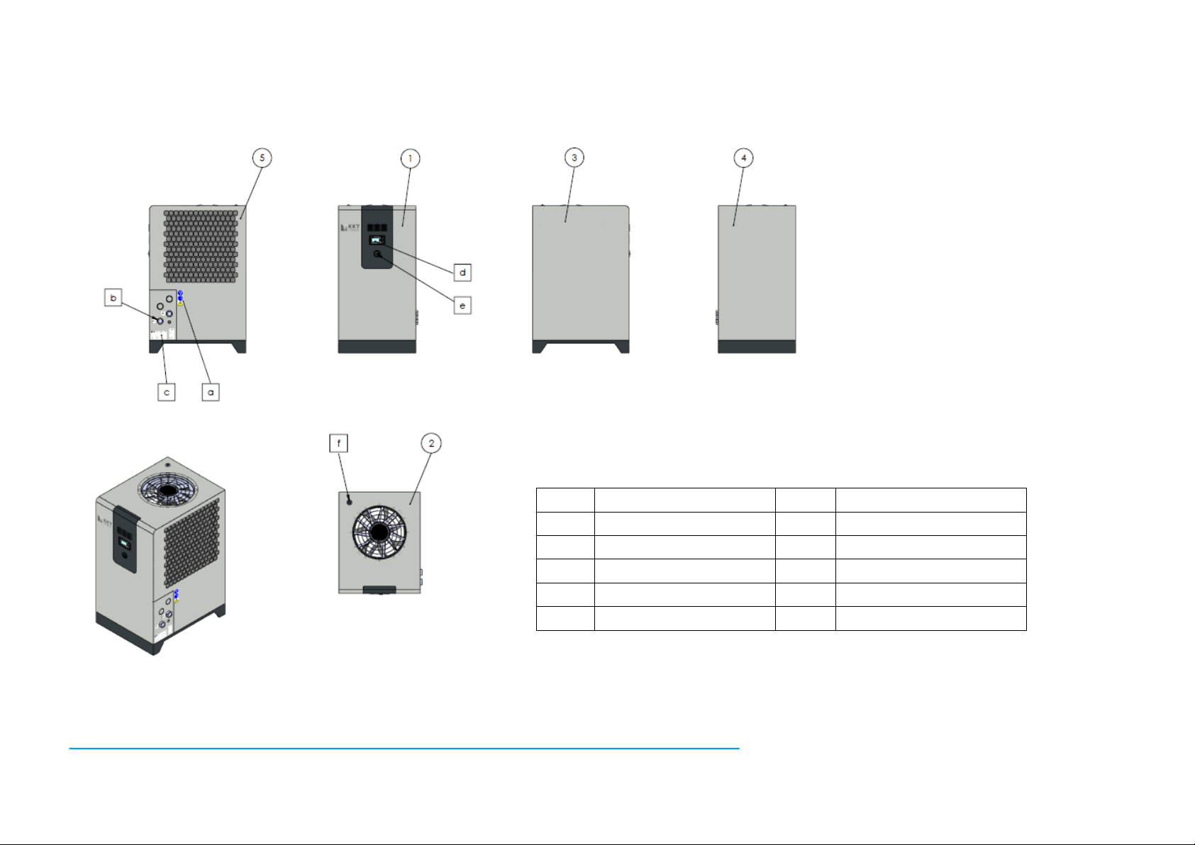
1
Operating side
a
Safety instructions
2
Cover
b
Water connections
3
Service side tank
c
Nameplate
4
Service side compressor
d
Display
5
Condenser safety grille
e
Main switch
f
Tank filling
1.2. Elements
10 / 82 83000602.Ke

Term
Explanation
Application
The heat source connected hydraulically with the chiller.
Process circuit
Application and piping to the chiller.
Cold water circuit
Process circuit and chiller in hydraulic piping.
Cold water
Liquid medium in the cold water circuit.
Cooling air
Ambient air drawn in by the machine, which absorbs the heat.
Net weight
Ready to use machine without cold water.
Gross weight
Ready to use machine including cold water.
1.3. Explanation of the terms used
For improved understanding, several important terms which are used frequently in this document
are briefly explained here.
Table 4: Explanation of the terms used
11 / 82 83000602.Ke
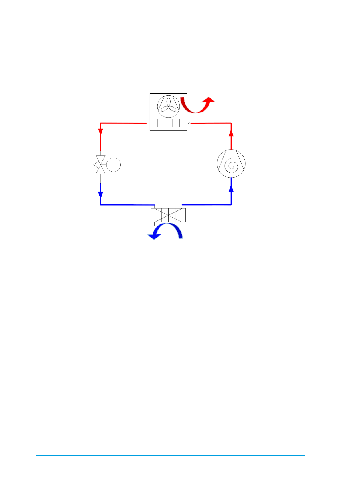
Compressor
Condenser and fan
Evaporator
Expansion
valve
Heat
Cold
2. Function and main components
The chiller consists of the main components: compressor, condenser, expansion valve and
evaporator, which are arranged in a circuit (Figure 1). Refrigerant circulates in this circuit. This
absorbs heat from the cold water and discharges this to the ambient air drawn-in in the condenser.
Figure 1: C6848 Refrigeration diagram
Diverse pressure and temperature sensors, a control unit, a high-pressure switch, one or several
pump(s) and a fan are also installed for control and operation of the chiller.
2.1. Compressor
The compressor generates the pressure difference in the refrigerant circuit, between the heat sink
and heat source, necessary for evaporation and condensing. Vaporous refrigerant from the
evaporator is drawn in and is compressed to condensing pressure in the compressor.
The compressors used in the Vario-Line are speed-controlled and therefore adapt automatically to
the requested load profile – and therefore the chiller always operates with maximum energy
efficiency.
12 / 82 83000602.Ke

2.2. Evaporator
The evaporator is a plate heat exchanger, which transfers heat from the cold water to the
refrigerant. In order for the heat transfer to take place, the refrigerant in the evaporator has a lower
temperature than the cold water and when it absorbs heat its aggregation state changes from liquid
to gaseous. If the cold water is contaminated with dirt, deposits can form on the transfer surfaces
of the evaporator. These worsen heat transfer to the refrigerant and have a negative effect on the
machine's refrigeration capacity. For this reason you must always pay attention to the specified
water quality and must not use any additives other than those specified.
2.3. Condenser
The condenser is a microchannel heat exchanger, which transfers heat from the refrigerant to the
ambient air. In order for the heat transfer to take place, the refrigerant in the condenser has a
higher temperature than the drawn-in ambient air and when it transfers heat its aggregation state
changes from gaseous to liquid.
Contaminated cooling air can cause deposits to form on the condenser's surface over time. This
has a negative effect on heat transfer to the refrigerant. This limits the machine's use limit and also
reduces the machine's refrigeration capacity. How to clean the condenser is described in Chapter
9 Cleaning. If you operate your chiller in an environment contaminated with dust or oil vapour, use
the optionally available air filter mat (see Chapter 3.24 Air filter mat).
If a cooling water system is available and the hot waste air of the chiller is to be avoided, the chiller
can also be designed with a water-cooled condenser (see Chapter 3.3 Version with water-cooled
condenser).
2.4. Expansion valve
The expansion valve controls the liquid refrigerant impinging the evaporator and at the same time
controls the refrigerant load before it enters the evaporator. This flow restriction causes the
refrigerant to cool to the evaporation temperature.
The expansion valve used in your machine is controlled electronically. The electronic control
ensures that the evaporator is always optimally loaded with refrigerant. This improves the COP
(coefficient of performance) and reduces pressure fluctuations in the refrigeration cycle.
2.5. Refrigerant
The refrigerant R410A circulates in the refrigeration circuit. It "transports" heat from the evaporator
to the condenser and in doing so changes its aggregation state continuously.
R410A is a fluorinated greenhouse gas consisting of the zeotropic mixture of 50% R32 and 50%
R125 with virtually negligible glide. R410A has a very high volumetric refrigerating capacity and has
no ozone depletion potential (ODP=0). A corresponding safety data sheet can be requested from
our KKT chillers service team (see Table 1: Contact details).
13 / 82 83000602.Ke

2.6. Oil
The compressor components affected by friction are lubricated with oil, which is added in the
factory by the compressor manufacturer. The polyolestor oil FV50S is used for this. The oil is soluble
in the refrigerant and distributes itself with the refrigerant in the whole refrigerating circuit. A
corresponding safety data sheet can be requested from our KKT chillers service team (see Table
1: Contact details).
2.7. Filter dryer
The task of the filter drier is to absorb any contaminations (dirt) or moisture from the refrigerant
circuit. Both the refrigerant and the oil act hygroscopically. When the refrigeration circuit is installed
the oil can absorb moisture. This moisture can cause corrosion and have a negative effect on the
refrigeration process. The filter dryer binds this moisture and also has a mechanical filter effect. If
work is carried out on the refrigeration circuit, in which it is opened, it is necessary to change the
filter dryer.
2.8. Pressure sensors
The pressure sensors used are compact pressure transmitters with piezoresistive measuring cell.
The sensors record the system pressure continuously in various places in the refrigerant and cold
water circuit. The values are used to control the system and for visualisation at the controller
display.
2.9. Temperature sensors
The temperature sensors used are equipped with a platinum measuring cell. The sensors record
the temperature continuously in various places in the refrigerant and cold water circuit. The values
are used for to control the system.
2.10. Control unit
The control unit is a control system programmed in the factory. All system measured values and
information converges in this control system. The electrical components are also controlled via
algorithms.
2.11. Display
The days is used to visualise information required by the operator and the system processes. It is
also possible to make entries. The display communicates with the control unit. Further information
on operating the chiller is given in Chapter 8.5 Control unit.
2.12. Control cabinet
The control cabinet conforms to the EN 60204 regulations and contains the electrical and
electronic components to control the chiller. To open the control cabinet, undo the screws in the
front panel first (hexagon socket, 4mm). Then tilt the front panel forward slightly and lift it out from
above (see figure below). Now open the control cabinet door with the corresponding control cabinet
key.
14 / 82 83000602.Ke
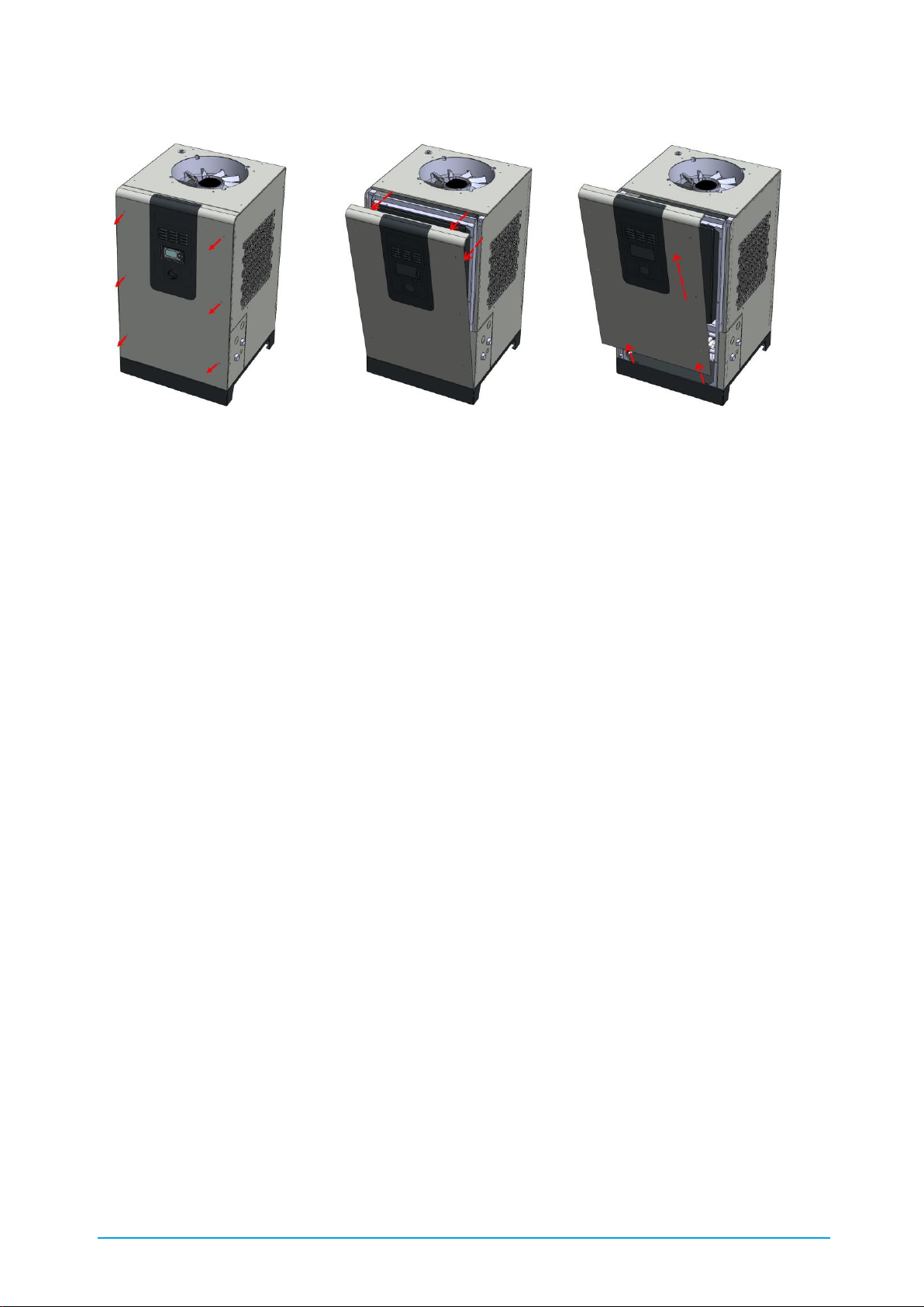
Figure 2: Opening the control cabinet
2.13. Pump
The chiller's pump ensures the necessary circulation of the cold water. This is drawn out of the
chiller's internal tank and is pumped through the process circuit. The units can also be supplied
optionally as continuous flow coolers without tank, with pump or without tank and without pump
(see Chapter 3.1 Version without tank, with pump and Chapter 3.2 Version without tank, without
pump).
2.14. Fan
The fan draws the cooling air from the surroundings through the condenser and blows the heated
air upwards and out of the refrigeration machine (chiller). To prevent injuries the fan is secured
against accidental touch by means of protective grilles on the discharge side. The fan's speed is
variable and is controlled by the main circuit board. The speed of the fan is essentially determined
by the condensation pressure.
2.15. Cold water circuit
The cold water is drawn out of the internal tank of the chiller by the internal pump and is pumped
through the process circuit. The units can also be supplied optionally as continuous flow coolers
without tank, with pump or without tank and without pump (see Chapter 3.1 Version without tank,
with pump and Chapter 3.2 Version without tank, without pump). In the process circuit the cold
water absorbs heat. The circuit closes when the cold water is pumped back into the chiller. It flows
through the evaporator in which it gives off heat. The cold water then returns to the tank. The cycle
begins again.
15 / 82 83000602.Ke

16 / 82 83000602.Ke
Component
Material
Unit connections
V2A 1.4305
Evaporator
V2A 1.4301 and copper (99.9%)
Tank
Tank connection sockets
V2A 1.4301
V4A 1.4305
Pump
Mechanical seal
V2A 1.4301
EPDM
Yellow sealing plugs
Polyamide PA 6
Black sealing plugs
Polyoxymethylene (POM)
Fill and drain tap
Nickel-plated brass
Bends, tees, sockets
Red brass CC499K, brass
Temperature sensor
V2A 1.4401 – AISI316
Pressure sensor
V2A 1.4301
Overflow valve (optional)
Red brass
Tank heater (optional)
Nickel-chrome-iron alloy - Alloy 825
Water circuit
John Guest piping made of polybutylene,
Hose made of synthetic rubber
Pushfit fitting
Acetal copolymer, nitrile (NBR), V2A
Component
Material
Unit connections
V2A 1.4305
Evaporator
V2A 1.4301
Tank
Tank connection sockets
V2A 1.4301
V4A 1.4305
Pump
Mechanical seal
V2A 1.4301
EPDM
Yellow sealing plugs
Polyamide PA 6
Black sealing plugs
Polyoxymethylene (POM)
Fill and drain tap
V2A 1.4301
Bends, tees, sockets
V2A 1.4301
Temperature sensor
V2A 1.4401 – AISI316
Pressure sensor
V2A 1.4301
Overflow valve (optional)
V2A 1.4301 / Plastic
Tank heater (optional)
Nickel-chrome-iron alloy - Alloy 825
Water circuit
John Guest piping made of polybutylene (BGI)
Hose made of synthetic rubber (BGII)
Pushfit fitting
Acetal copolymer, nitrile (NBR), V2A
2.16. Materials used in the water circuit
The basic fitout has the material composition shown in Table 5:
Table 5: Materials used in the basic version
If the units are fitted with the Water circuit made free from non-ferrous metals option the material
composition is as shown in Table 6:
Table 6: Materials used in the non-ferrous metal-free version
17 / 82 83000602.Ke

Property /
component parts
Unit
Value range
Standard version
Value range
Non-ferrous metal-free version
pH value (20°C) - 7-9
6-9
Saturation index
-
-0.2 < 0 < +0.2
-0.2 < 0 < +0.2
Conductivity
µS/cm
80-500
5-500
Water hardness
°dH
<5.6
<5.6
Carbonate
hardness
mol/m³
<0.5
<0.5
Total bacterial
count
K/ml
<10,000
<10,000
Particle size
µm
< 250
< 250
Glycol fraction
(AFN)
% by
vol
20-40
20-40
Oil fraction
% by
vol
0
0
Chloride (Cl-)
mg/l
<50
<50
Sulphate
mg/l
<50
<50
Nitrate
mg/l
<100
<100
Copper
mg/l
<0.1
<0.1
Iron
mg/l
<0.2
<0.2
Free carbon
dioxide
mg/l
<20
<20
Manganese
mg/l
<0.1
<0.1
Ammonia
mg/l
<2
<2
Free chloride
mg/l
<0.5
<0.5
Sulphide
mg/l
<0.03
<0.03
2.17. Water quality
The following limit values must be adhered to, to ensure safe operation of the units:
Table 7: Water quality
The specified limit values must always be complied with in order to avoid blockaging of the plate
heat exchanger.
Furthermore, slime-forming bacteria must be prevented in the cooling water. If this is not possible,
KKT chillers can recommend or provide an appropriate inhibitor to remove the slime forming agents
on the basis of a biological water analysis carried out in advance.
18 / 82 83000602.Ke
WARNING! Do not use mixtures of different anti-freezes. This can cause unwanted
chemical reactions and silting-up.
Setting
Frost free up to
Mix ratio AFN
Mix ratio AFL
Glycol 20 - 25 %
-10°C
20-25 %
25-30 %
Glycol 30 - 35 %
-15°C
30-35 %
32-37 %
Glycol 40 %
-25°C
40 %
42 %
2.18. Allowable liquids
Water and mixtures of water / Antifrogen N (AFN) or water / Antifrogen L (AFL) according to the
details in Chapter 2.17 Water quality. The following table shows the requirements for the mix ration
of water with antifreezes AFN and AFL. These values must be kept to as accurately as possible in
order to maintain your machine's efficiency and prevent damage to components.
Table 8: AFN and AFL (or equivalent) mix ratios
19 / 82 83000602.Ke

3. Options and accessories
The chiller can be equipped in the factory with the options described in the following.
The items marked with "accessory" are enclosed with the unit and can also be ordered later at any
time under the relevant product number. The installer of the machine is responsible for installation
of the accessory. You can also ask our KKT chillers service team to carry out this installation (see
Table 1: Contact details).
Details of your machine fitout are given in the separate quick start documentation.
3.1. Version without tank, with pump
The Vario-Line units are optionally available as continuous flow coolers. The units are delivered
without an internal tank in the unit. The temperature sensor is then located in the cooler's return
line. If a tank open to the atmosphere is integrated on site, ensure that the tank is not installed at
a lower geodetic level than the cooler. Additional pressure losses between the tank provided on
site and the integrated pump are to be avoided (dp
=0.3bar)
max
3.2. Version without tank, without pump
The Vario-Line units are optionally available as continuous flow coolers. The units are delivered
without an internal tank in the unit and without a pump. The temperature sensor is then located in
the cooler's return line. The cold water is then circulated via the evaporator by a pump to be
installed on site. This must at least be designed for the pressure loss of the whole system.
3.3. Version with water-cooled condenser
While the basic variant of the Vario-Line has an air-cooled condenser, it is also possible to purchase
the individual units in this series with water-cooled condensers.
Figure 3: C6848 Refrigeration diagram
The condensers used are plate heat exchangers, whose stainless steel plates are copper soldered.
The 3-way valve is located in the cooling water outlet and is controlled via a servomotor according
to the condensation pressure. By closing the additional bypass valve provided it is possible to switch
from 3-way to 2-way control.
20 / 82 83000602.Ke

The water quality listed under Table 7: Water quality must be complied with – the
manufacturer does not accept any liability whatsoever for damage caused by a
different water specification!
The cooling water temperature is recorded by an additional temperature sensor in the cooling water
inlet and is displayed at the controller display.
The project-specific data and adapted PI flow chart and dimensioned diagram are given in the
enclosed quick-start documentation.
3.4. Control cabinet heating
The control cabinet heating is controlled thermostatically and, at lower ambient temperatures,
prevents moisture from the drawn in ambient air from condensing on and damaging the electrical
and electronic components of the control cabinet.
In order for the control cabinet heating to be active the chiller must not be disconnected from the
power supply (see Chapter 8.2 Selecting the operating mode).
3.5. Insulation of the cold pipes and pump(s)
In order to prevent condensation on cold pipes of the chiller, where high temperature differences
exist between the surroundings and cold water flow and taking into account the relative humidity
the cold pipe insulation option must be specified.
21 / 82 83000602.Ke

vBoxX
Frost-free area
Application
Application
vBoxX
3.6. Tank heating with thermostatic pump start
The tank heating is used to maintain a minimum temperature in the tank. The pump circulates the
cold water while the tank heating controls the temperature in the system. We recommend a
hydraulic installation as shown in Figure 4. Any bypass valves must therefore always be installed
frost-free. In order for the heating to be active the chiller must not be disconnected from the power
supply. Even if the external release is deactivated (Chapter 8.3 External release), the pump remains
active.
Figure 4: C6856 thermostatic pump start with overflow valve (installation recommendation)
3.7. Overflow valve for standby operation
The overflow valve option should be installed if there is a possibility of the application severely
reducing or completely preventing flow of the cold water while the machine is running. The internal
overflow valve ensures the minimum flow rate through the chiller and therefore prevents the pump
from switching off. Figure 5 shows the position of the internal overflow valve.
Figure 5: C6863 overflow valve for standby operation
22 / 82 83000602.Ke

3.8. Higher pressure pump
The standard Vario-Line units are designed with a 3 bar pump, which is designed to the nominal
flow rate of the respective unit. Optionally, the units can also be supplied with higher pressure
pumps within the minimum or maximum flow rate limits. The pump characteristic of the pump(s)
used in your unit is enclosed with the unit.
3.9. Speed-controlled pump
On request the Vario-Line units can also be supplied with a speed-controlled pump. The delivery
head and the delivery rate are adjusted automatically to the system characteristic of the overall
system. This means that the pump output can be adjusted to a minimum and the power
consumption reduced.
3.10. Additional evaporator pump
The evaporator is optimised for the nominal flow rate of cold water. The nominal flow rate is listed
in Table 3: Technical specifications. If the operating flow rate of the cold water is more than 50 %
lower an evaporator pump must be installed. The evaporator pump circulates the cold water
internally and keeps the stored water at flow temperature. A second pump supplies the process
circuit with cold water.
3.11. Second load pump
The standard Vario-Line units are designed with a 3 bar pump, which is designed to the nominal
flow rate of the respective unit. If a second load with the same liquid and same liquid temperature
but different liquid quantity or different flow pressure is to be supplied, the unit can also be
optionally supplied with a second load pump.
3.12. Second temperature level
If several loads with the same liquid but with different temperature levels are to be supplied, a
second setpoint can be specified for the secondary circuit. In this case an additional temperature
sensor records the temperature in the secondary circuit. A control valve adds a partial flow rate of
the primary circuit until the required setpoint is reached in the secondary circuit.
3.13. Second medium
If several loads with different liquids are to be supplied, an optional second tank, which is filled with
a different medium to the primary circuit, can be provided. Both circuits are separated from each
other hydraulically by an additional plate heat exchanger. Similar to the above-named option, a
control valve adds a partial flow rate of the primary circuit until the required setpoint is reached in
the secondary circuit.
23 / 82 83000602.Ke

3.14. Automatic water feed
Any leaks and evaporation during the course of the operation can reduce the required quantity of
cold water available for the chiller function. The Automatic water feed option makes it possible to
top up the cold water circuit automatically. The tank contents are monitored continuously and if
necessary additional water is fed in until it has reached the optimum level once again. The owner
(user) only has to connect the chiller to the building's water system via the feed connection (see
Figure 6). The inlet pressure must lie between 1 bar and 10 bar.
Figure 6: Feed water connection
An initial fill by means of the feed water can only be carried out by activating the corresponding
controller function. Further details are given in Chapter 6.2.15 Flushing the cold water circuit.
If you operate your chiller with a water / glycol mixture and only feed in pure water, you must check
the glycol content of the circuit water regularly and adjust if necessary.
3.15. Flow control switch
Optionally, the Vario-Line units can also be equipped with a flow control switch. The flow control
switch triggers if the flow drops and falls below the switching value. The corresponding signal can
be tapped, floating, at the terminal in the control cabinet.
3.16. Water circuit made free from non-ferrous metals
If you machine is made free from non-ferrous metals, all parts of the chiller's cold water circuit
touched by the media are free from non-ferrous metals. Several components such as the
evaporator and pump have been adjusted. The materials used for the water circuit are given in
Table 6.
3.17. Conductance monitoring
In the conductance monitoring option the conductance is recorded by a measuring probe in the
tank. A warning is output depending on whether the specified conductance setpoint is exceeded or
not reached (see parameter list).
3.18. Conductance control
In the conductance control option the conductance is recorded via a measuring probe in the tank.
If the required conductance is exceeded, a regulating valve opens and allows a partial flow rate of
the liquid to flow via DI cartridge installed in the bypass. The regulating valve closes as soon as the
required conductance has been reached once again.
3.19. Special voltage
If your machine is equipped for a special voltage, electrical components have been adjusted. Your
machine must be operated only under the voltage noted on the nameplate.
24 / 82 83000602.Ke

3.20. Phase monitoring
Optionally, the Vario-Line units can be equipped with so-called phase monitoring. This monitors the
phase sequence, phase failure, undervoltage and asymmetry and covers a voltage range of 200690V. If the respective predefined limits are exceeded the system switches off and protects the
electrical components installed in the unit.
3.21. Output control < ±0.5K
If more precise setpoint constancy than ±0.5 Kelvin is required, the chiller can be equipped with
output control. Here the output of the refrigeration circuit is adjusted to the refrigeration demand
by an electronically controlled valve.
3.22. UL version
The main components of the Vario-Line are already designed to conform to UL in the basic fitout. If
your unit is ordered with the UL version option, the control cabinet is also produced in accordance
with the UL regulations. The corresponding UL certificate must then be issued separately within the
scope of the official UL acceptance – please ask your customer consultant.
3.23. Special paint finish
All façade panels (see Chapter 1.2 Elements) can also be optionally supplied with a special paint
finish.
3.24. Air filter mat (accessory)
If the chiller is operated in an environment contaminated with dust or oil vapour, the condenser
should be protected with the air filter mat. The filter is fixed in place using the Velcro tapes attached
in the condenser safety grille. The filter is removed for cleaning and is washed out with water or a
mild lye (alkaline solution). Highly soiled filters must be replaced by a new filter. Please contact the
KKT chillers service team (Contact details).
3.25. Vario Foot (accessory)
The four levelling feet of the Vario Foot can be used for rolling, vibration isolation and for height
adjustment. To do this, the height of each foot can be individually adjusted up or down using a
special ratchet function. If the unit is out of service, all four feet can be screwed in until the unit
stands on the integrated machine rollers and can be rolled away.
3.26. Level package (accessory)
The level package is used if the application is to be installed more than 500 mm above the chiller
(see also Chapter 6.2.7 Process level). This option is delivered separately with the unit (i.e. is not
installed) and consists of an electrically activated valve and a check valve. The electrically activated
valve is to be installed at the unit inlet, the check valve at the unit outlet. The valve is installed
electrically in the control cabinet as shown in the electric circuit diagram.
25 / 82 83000602.Ke
 Loading...