

KKT chillers nBoxX 1.5, nBoxX 4.5, nBoxX 3.0, nBoxX 6.0 Operating Instruction
Nano
NanoNano
Nano----Line
LineLine
Line
nBoxX 1.5
nBoxX 3.0
nBoxX 4.5
nBoxX 6.0
Operating Instruction

2 / 48 83000902.Ka
Content
ContentContent
Content
1 Notes on documentation ....................................................................................... 4
1.1
Other applicable documents ...................................................................................................................... 4
1.2
CE conformity .............................................................................................................................................. 4
1.3
Storing the documents ............................................................................................................................... 4
1.4
Symbols used .............................................................................................................................................. 4
2 Safety instructions ................................................................................................ 5
2.1
Risks in case of failure to observe the safety instructions ....................................................................... 5
2.2
Safety instructions for the operator ........................................................................................................... 5
2.3
Safety instructions for assembly, inspection and maintenance work ...................................................... 5
2.4
Unauthorised operation .............................................................................................................................. 6
2.5
Health risks due to the refrigerant R134a and the antifreeze ................................................................. 6
2.5.1 First aid measures ......................................................................................................................... 6
2.5.2 Fire-fighting measures .................................................................................................................. 6
2.5.3 Protective measures during repairs .............................................................................................. 6
3 Device description ................................................................................................. 6
3.1
General functional description ................................................................................................................... 9
3.1.1 Controller ..................................................................................................................................... 10
3.1.2 Safety devices ............................................................................................................................. 10
3.2
Proper use ................................................................................................................................................ 10
4 Transportation ..................................................................................................... 11
5 Assembly and connection .................................................................................. 12
5.1
Installation site requirements ................................................................................................................. 12
5.2
Installing the cooling unit ......................................................................................................................... 13
5.3
Making the hydraulic connection ............................................................................................................ 13
5.4
Making electrical connection................................................................................................................... 14
5.4.1 Connecting the power supply ...................................................................................................... 14
5.4.2 Connecting the alarm relay interrogation device ......................................................................... 15
5.4.3 External activation ....................................................................................................................... 15
5.4.4 Connecting the cooling unit to the PLC ....................................................................................... 15
6 Commissioning .................................................................................................... 17
6.1
Antifreeze .................................................................................................................................................. 17
6.2
Filling the cooling system with cooling medium ..................................................................................... 17
6.3
Bleeding the cooling medium pump ....................................................................................................... 18
7 Operation .............................................................................................................. 19
7.1
Controls ..................................................................................................................................................... 19
7.2
Key functions ............................................................................................................................................ 20
7.2.1 Key functions during operation .................................................................................................... 20
7.2.2 Key functions during parameter adjustment ................................................................................ 21

3 / 48 83000902.Ka
7.3
Fixed value control or combined control ................................................................................................. 22
7.4
Meaning of the control parameters ........................................................................................................ 23
7.5
Meaning of the error codes ..................................................................................................................... 27
7.6
Alarm relay contacts ................................................................................................................................ 29
7.7
PLC outputs .............................................................................................................................................. 30
7.8
Setting the digital real-time clock ............................................................................................................ 31
8 Inspection and maintenance .............................................................................. 32
8.1
Maintaining the refrigerant circuit ........................................................................................................... 33
8.2
Water quality ............................................................................................................................................ 33
8.3
Cleaning the condenser ........................................................................................................................... 36
8.4
Cleaning the filter mat (optional) ............................................................................................................. 37
8.5
Draining the cooling medium tank .......................................................................................................... 37
9 Troubleshooting .................................................................................................. 38
10 Shutting down and disposal ............................................................................... 38
10.1 Shutting down for an extended period .................................................................................................... 38
10.2 Shutting down and disposal .................................................................................................................... 39
11 Manufacturer’s guarantee and customer service ............................................. 40
12 Annex .................................................................................................................... 42
P+ID-diagram
Technical data
Electrical schematic
Parameter list
Spare part list
Declaration of conformity
4 / 48 83000902.Ka
1111 Notes on documentation
Notes on documentationNotes on documentation
Notes on documentation
These instructions are aimed at installers and operators who are familiar with the installation and
the operation of the cooling unit.
Thereby it is imperative that you observe the following:
You must read and observe these operating instructions prior to commissioning. The manufacturer
will not accept any liability for damage or operating problems resulting from failure to observe these
operating instructions.
1.1
1.11.1
1.1 Other applicable documents
Other applicable documentsOther applicable documents
Other applicable documents
In conjunction with these instructions the flow diagram and electrical wiring diagram for the related
model apply.
1.2
1.21.2
1.2 CE conformity
CE conformityCE conformity
CE conformity
The declaration of conformity is included in the appendix of these installation and operating instructions.
1.3
1.31.3
1.3 Storing the documents
Storing the documentsStoring the documents
Storing the documents
These instructions and all associated documents constitute an integral part of the product. They
must be supplied to the operator. The plant operator is responsible for storage of the documents so
they are readily available when needed.
1.4
1.41.4
1.4 Symbols used
Symbols usedSymbols used
Symbols used
Please observe the following safety instructions and other notes in this guide:
Danger!
Danger!Danger!
Danger!
Immediate danger to life and limb!
Immediate danger to life and limb!Immediate danger to life and limb!
Immediate danger to life and limb!
Risk of burns!
Risk of burns!Risk of burns!
Risk of burns!
Risk of injury due to contact with hot fluids!
Risk of injury due to contact with hot fluids!Risk of injury due to contact with hot fluids!
Risk of injury due to contact with hot fluids!
Risk of cuts!
Risk of cuts!Risk of cuts!
Risk of cuts!
Risk of injury on touching the fins on the condenser!
Risk of injury on touching the fins on the condenser!Risk of injury on touching the fins on the condenser!
Risk of injury on touching the fins on the condenser!
Danger!
Danger!Danger!
Danger!
Danger of death due to electric shock!
Danger of death due to electric shock!Danger of death due to electric shock!
Danger of death due to electric shock!
Caution!
Caution!Caution!
Caution!
Possible hazard for the cooling unit.
Possible hazard for the cooling unit. Possible hazard for the cooling unit.
Possible hazard for the cooling unit.

5 / 48 83000902.Ka
Caution!
Caution!Caution!
Caution!
Possible hazard due to discharge of refrigerant.
Possible hazard due to discharge of refrigerant.Possible hazard due to discharge of refrigerant.
Possible hazard due to discharge of refrigerant.
Note!
Note!Note!
Note!
Useful information and special features.
Useful information and special features.Useful information and special features.
Useful information and special features.
Symbol for an instructed action:
Symbol for an instructed action:Symbol for an instructed action:
Symbol for an instructed action:
The bullet point indicates that you should perform an action.
2222 Safety instructions
Safety instructionsSafety instructions
Safety instructions
Please observe the following general safety instructions when operating and installing the cooling
unit: Assembly, installation and maintenance must only be carried out by qualified personnel.
Only use original spare parts and accessories authorised by the manufacturer to ensure the protection and safety of the cooling unit. The usage of other parts will render any liability void. Do make any
changes to the cooling unit that have not been agreed with and approved by the manufacturer.
It is also imperative that you observe the special safety instructions for the individual activities in the
individual chapters.
2.1
2.12.1
2.1 Risks in case of failure to observe the safety instructions
Risks in case of failure to observe the safety instructionsRisks in case of failure to observe the safety instructions
Risks in case of failure to observe the safety instructions
In case of failure to observe the safety instructions, people, the environment and the unit may be
placed at risk. Failure to comply with the safety notes makes all claims for compensation void.
2.2
2.22.2
2.2 Safety instructions for the operator
Safety instructions for the operatorSafety instructions for the operator
Safety instructions for the operator
Any existing contact hazard protection for moving parts must not be removed from units while operational. Hazards due to electrical power, do not remove any switch box cover!
2.3
2.32.3
2.3 Safety instructions for a
Safety instructions for aSafety instructions for a
Safety instructions for assembly, inspection and maintenance work
ssembly, inspection and maintenance workssembly, inspection and maintenance work
ssembly, inspection and maintenance work
Cleaning and maintenance work on the unit must only be performed with the unit shut down. For this
purpose, it is vital to ensure that the unit is disconnected from the power supply and is secured
against switching back on.
It is imperative that you observe the procedure for shutting down the cooling unit described in the
operating instructions. All safety devices and protective equipment must be reattached or put in a
functional condition immediately after the work is complete.
Modifications or changes to the cooling unit are not allowed. Only appropriately qualified personnel
as defined by BGR500 chap. 2.35 / EN 378 are allowed to work on the refrigerant circuit.
6 / 48 83000902.Ka
Caution!
Caution!Caution!
Caution!
Possible hazard for the cooling unit.
Possible hazard for the cooling unit. Possible hazard for the cooling unit.
Possible hazard for the cooling unit.
Do not install the unit without protection outside of covered areas, or in an explosive or aggressive
environment. Do not install the unit on an unstable surface or a surface that is not designed for the
weight of the cooling unit. Do not bypass any electrical safety devices to make it possible to operate
the cooling unit.
2.4
2.42.4
2.4 Unauthorised operation
Unauthorised operationUnauthorised operation
Unauthorised operation
The safety of the cooling unit supplied is only ensured if it is used properly, see chapter 3.2. Under
no circumstances should the limit values specified in the technical specifications be exceeded.
The unit must not be used for the direct cooling of liquids that are used for foodstuffs (e.g. drinking
water).
Exp
ExpExp
Explosion hazard!
losion hazard!losion hazard!
losion hazard!
The use of the
The use of the The use of the
The use of the cooling system for cooling inflammable or pyrophoric substances is pr
cooling system for cooling inflammable or pyrophoric substances is prcooling system for cooling inflammable or pyrophoric substances is pr
cooling system for cooling inflammable or pyrophoric substances is pro-
o-o-
o-
hibited.
hibited. hibited.
hibited.
2.5
2.52.5
2.5 Health risks due to the refrigerant R134a and the antifreeze
Health risks due to the refrigerant R134a and the antifreezeHealth risks due to the refrigerant R134a and the antifreeze
Health risks due to the refrigerant R134a and the antifreeze
The refrigerant is a liquefied gas under pressure. The enclosed R134a safety data sheet must be
observed. The antifreeze is a liquid fluid. The enclosed Antifrogen N safety data sheet is to be observed.
2.5.1
2.5.12.5.1
2.5.1 First aid measures
First aid measuresFirst aid measures
First aid measures
(see safety data sheets R134a and Antifrogen N)
2.5.2
2.5.22.5.2
2.5.2 Fire
FireFire
Fire----fighting measures
fighting measuresfighting measures
fighting measures
All known extinguishing agents can be used.
2.5.3
2.5.32.5.3
2.5.3 Protective measures
Protective measuresProtective measures
Protective measures during repairs
during repairsduring repairs
during repairs
Protective measures
Protective measuresProtective measures
Protective measures::::
• Ensure adequate ventilation.
Personal protection equipment
Personal protection equipmentPersonal protection equipment
Personal protection equipment::::
• Hand protection: Protective gloves
• Eye protection: Safety glasses
• Body protection: Wear safety shoes when handling pressurised gas bottles.
3333 Device
Device Device
Device description
descriptiondescription
description
The cooling units are used for the central and economical cooling and supply of a cooling medium
(water + glycol, see chapter Water Quality) in the event of physical separation between the place
where cooling is required and the refrigeration. The cooling medium is supplied using a pipe system.
7 / 48 83000902.Ka
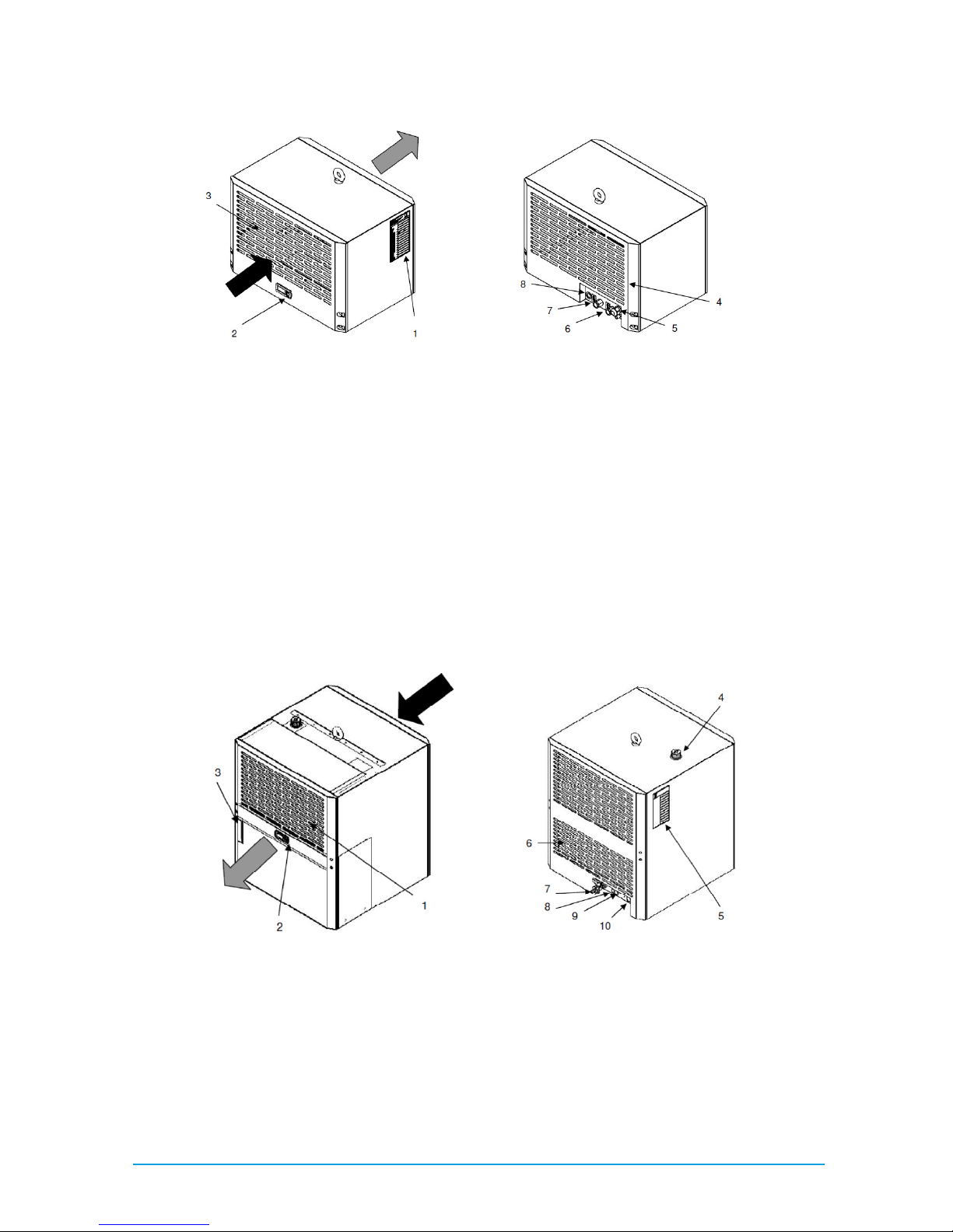
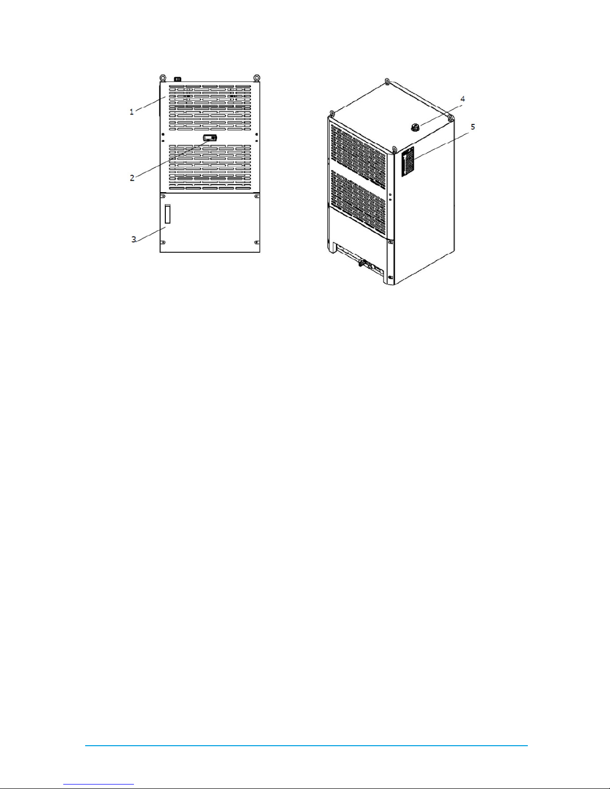
Fig. 1 nBoxX1.5 View from front (left) and rear (right)
Key to figures 1
Key to figures 1 Key to figures 1
Key to figures 1
1 Rating plate
2 Display
3 Louvered grille for air inlet
4 Louvered grille for air outlet
5 Cable entry
6 Cooling medium inlet
7 Tank drain nozzle for maintenance, transportation and disposal of the cooling medium
8 Cooling medium return
Fig. 2 nBoxX3.0 and nBoxX4.5 View from front (left) and from rear (right)
8 / 48 83000902.Ka
Fig. 3 nBoxX6.0 View from front (left) and from rear (right)
Key to figures 2 and 3
Key to figures 2 and 3Key to figures 2 and 3
Key to figures 2 and 3
1 Louvered grille for air outlet (two-part)
2 Display
3 Liquid level display of cooling medium
4 Tank filling nozzle for cooling medium
5 Rating plate
6 Louvered grille for air inlet (two-part)
7 Tank drain nozzle for maintenance, transportation and disposal of the cooling medium
8 Cable entry
9 Cooling medium inlet/outlet
10 Cooling medium return/inlet
For the closed cooling units, we recommend the installation of a pressure manometer, 0 – 6 bar, in
the cooling medium circuit.
9 / 48 83000902.Ka
3.1
3.13.1
3.1 General functional description
General functional descriptionGeneral functional description
General functional description
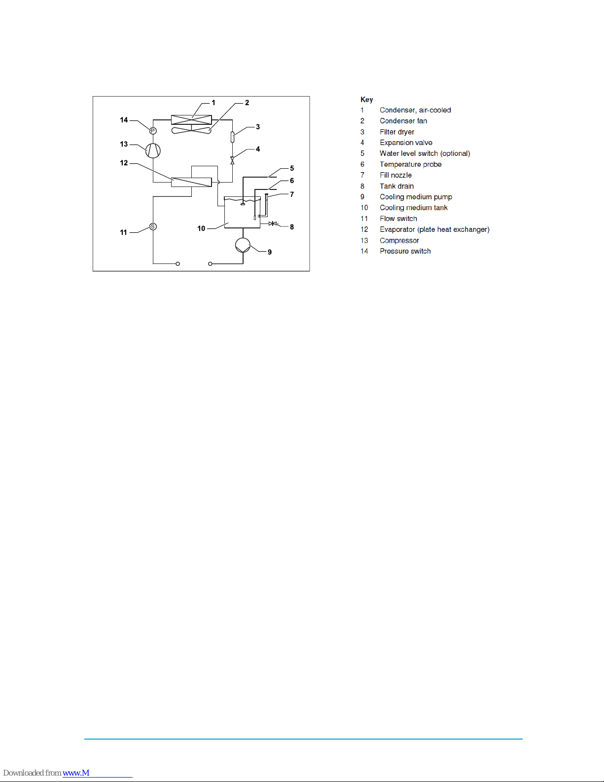
Fig. 4 Refrigerant circuit (schematic diagram: example, units with open refrigerant circuit)
The cooling system comprises the four main components: evaporator (12
1212
12), compressor (13
1313
13), condenser (1111) with fan (2222) as well as the control or expansion valve (4444), which are connected together by
pipes. A pressure switch (14
1414
14) limits the maximum pressure in the refrigerant circuit. The R134a
(CH2FCF3) refrigerant is free from chlorine. Its Ozone Depletion Potential (ODP) is 0.
A filter dryer (3333) which is integrated into the hermetically sealed refrigerant circuit provides effective
protection against moisture, acid, dirt particles, and foreign bodies. A temperature control with temperature probe (6666) ensures that the cooling medium is maintained at a preset set-point temperature.
In the evaporator (12
1212
12), the liquid refrigerant is converted to a gaseous state. The heat necessary for
this purpose is taken from the cooling medium in the plate heat exchanger, which has the effect of
cooling the cooling medium. The refrigerant is heavily compressed in the compressor (13
1313
13). As a result the refrigerant has a higher temperature than the ambient air. This heat is dissipated to the ambient air over the surface of the condenser (1111), resulting in the refrigerant liquefying again.
The refrigerant is injected into the evaporator (12
1212
12) using a thermostatic expansion valve (4444), as a
result it is expanded and is therefore able to absorb the heat from the cooling medium (water, waterglycol mixture).
The cooling medium is pumped to the equipment in a closed circuit using a pump (9999) and cooling
medium tank (10
1010
10). The flow switch (11
1111
11) ensures the evaporator (12
1212
12) is protected against freezing if
the flow rate is too low. The level switch (5,
5, 5,
5, optional) protects the pump (9999) against dry running. The
cooling medium (water or water-glycol mixture) feed temperature is regulated using the temperature
probe (6666) in the tank.
P
S
11
3
1
2
5
6
7
8
9
10
4
12
13
14
10 / 48 83000902.Ka
3.1.1
3.1.13.1.1
3.1.1 Controller
ControllerController
Controller
The cooling units are fitted with a controller for setting the functions of the cooling unit. Operating
states are displayed using a display unit and parameters can be set using buttons.
3.1.2
3.1.23.1.2
3.1.2 Safety devices
Safety devicesSafety devices
Safety devices
The cooling unit has a pressure switch in accordance with EN 12263, tested at component level, in
the refrigerant circuit; this device is set to the maximum permissible pressure (PS). An automatic
reset device ensures that the system continues to work after the pressure drops (auto-reset).
Temperature monitoring prevents the evaporator coil from icing over. If there is a risk of icing, the
compressor switches itself off and automatically switches itself back on again at higher temperatures.
The refrigerant compressor motor and the fan motors are equipped with thermal winding protection
switches against excess current and excess temperatures.
To ensure that the compressor runs reliably and without problems (for example after reaching the
set-point temperature or after a fault), the compressor automatically switches back on after a delay
of 180 seconds.
The cooling unit has two integrated floating fault signal contacts (see circuit diagram of the relevant
unit type, sections 13.4 and 13.5). Individual fault messages can be interrogated via an integrated
Sub-D socket using an external PLC controller.
3.2
3.23.2
3.2 Proper us
Proper usProper us
Proper useeee
The Nano-Line has been developed and designed in accordance with the state of the art and the
recognised rules governing safety. Nevertheless, if used improperly, they may pose a threat to life
and limb or cause damage to property. The Nano-Line units described in these instructions must only
be used for cooling water or a water-glycol mixture. If using other fluids (e.g. de-ionised water),
please refer to the technical specifications contained in the appendix, or contact the manufacturer.
Under no circumstances should the limit values specified in the technical specifications be exceeded.
Explosion hazard!
Explosion hazard!Explosion hazard!
Explosion hazard!
The use of the cooling unit for cooling inflammable or explosive substances is prohibited.
The use of the cooling unit for cooling inflammable or explosive substances is prohibited.The use of the cooling unit for cooling inflammable or explosive substances is prohibited.
The use of the cooling unit for cooling inflammable or explosive substances is prohibited.
11 / 48 83000902.Ka
4444 Transportation
TransportationTransportation
Transportation
If the cooling system is stored or transported at temperatures below freezing, you must completely
drain the cooling medium circuit and flush it with a water-glycol mixture to prevent frost damage. This
instruction also applies to the external condenser circuit for a water-cooled condenser (option).
Only transport the cooling unit in its original packaging material before commissioning for the first
time. In case of damage, inform the manufacturer without delay. When transporting the cooling unit,
the weight specified on the rating plate must be taken into consideration. Use lifting gear with an
appropriate minimum load capacity. To prevent transport damage to the unit, proceed as follows:
Only transport the unit in an upright position.
•
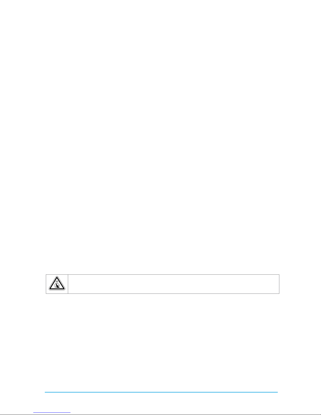
Fig. 5 Eyebolt for transportation (nBoxX 1.5 shown here as an example)
Only transport the unit on the pallet supplied with the unit or with the eyebolt provided (1).
Prevent excessive vibration. If it is necessary to move the unit in the factory, you must disconnect all
connections on the unit. Before transporting, empty the water circuit and tank (if applicable)
1
12 / 48 83000902.Ka
5555 Assembly and connection
Assembly and connectionAssembly and connection
Assembly and connection
5.1
5.15.1
5.1 IIIInstallation site requirements
nstallation site requirementsnstallation site requirements
nstallation site requirements
The site must be free from excessive dirt and moisture. The ambient temperature must not exceed
43°C. Install the cooling unit close to the equipment being cooled to avoid long distances and related performance losses. Performance losses arise in particular due to:
Pressure drops in the refrigerant piping system caused by resistance in the pipes and individual
components such as shut-off valves and pipe bends. Heat transfer in not insulated pipes.
Select the installation site such that: Easy access is possible at any time. This situation will ease
maintenance and repair. The condenser fan does not operate in a "short-circuit", whereby the warm
exhaust air from the condenser is drawn in again by the condenser's fan.
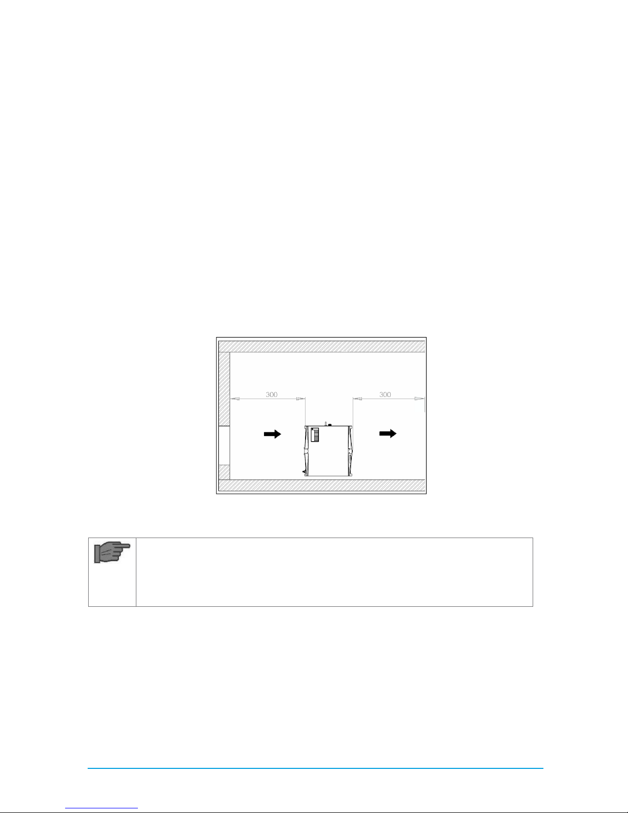
An "air short-circuit" will result in a loss of performance of the cooling unit. Maintain the following
minimum distances (in mm) from the wall:
Fig. 6 Space requirements
Note!
Note!Note!
Note!
For units of the type nBoxX1.5, the airflow passes through the unit from front to back.
For units of the type nBoxX1.5, the airflow passes through the unit from front to back.For units of the type nBoxX1.5, the airflow passes through the unit from front to back.
For units of the type nBoxX1.5, the airflow passes through the unit from front to back.
With unit of the types nBoxX3.0, nBoxX4.5 and nBoxX
With unit of the types nBoxX3.0, nBoxX4.5 and nBoxXWith unit of the types nBoxX3.0, nBoxX4.5 and nBoxX
With unit of the types nBoxX3.0, nBoxX4.5 and nBoxX 6.0 the airflow passes through
6.0 the airflow passes through 6.0 the airflow passes through
6.0 the airflow passes through
the unit from back to front.
the unit from back to front.the unit from back to front.
the unit from back to front.
Ensure the room is adequately ventilated by installing the cooling unit such that the heat dissipated
by the unit does not heat the room excessively.
The ambient temperature will increase due to the heat dissipated. This temperature increase may
cause a loss of performance of the cooling unit.
In case of installation in a "small" room, it is imperative that you provide forced ventilation, as otherwise the heat dissipated will build up.

13 / 48 83000902.Ka
The connection of ducts for fresh and exhaust air to our devices is not suitable, as these units are
equipped with axial fans and these cannot build up the necessary additional air pressure.
To prevent performance losses, do not install the cooling unit near any form of heating.
Outdoor siting: Cooling units must be installed such that they cannot become damaged by internal
traffic and transport operations.
5.2
5.25.2
5.2 Installing the cooling unit
Installing the cooling unitInstalling the cooling unit
Installing the cooling unit
Install the cooling unit on an even, firm surface. The maximum permissible deviation from the vertical is 2°. Avoid the production of noise due to vibration (vibration dampers, sheets of foam rubber)
5.3
5.35.3
5.3 Making the hydraulic connection
Making the hydraulic connectionMaking the hydraulic connection
Making the hydraulic connection
Caution!
Caution! Caution!
Caution!
Risk of damage to the circulation pump due to soiling in the cool
Risk of damage to the circulation pump due to soiling in the coolRisk of damage to the circulation pump due to soiling in the cool
Risk of damage to the circulation pump due to soiling in the cooling medium circuit!
ing medium circuit! ing medium circuit!
ing medium circuit!
Flush the cooling medium circuit prior to connecting to the cooling unit.
Flush the cooling medium circuit prior to connecting to the cooling unit.Flush the cooling medium circuit prior to connecting to the cooling unit.
Flush the cooling medium circuit prior to connecting to the cooling unit.
The cooling medium outlet on the cooling unit (must be connected to the cooling medium inlet on
the equipment to be cooled. The cooling medium inlet on the cooling unit must be connected to the
cooling medium outlet on the equipment to be cooled.
Use only insulated pipes and/or hoses to connect the equipment to the cooling unit.
The nominal size of the piping must be at least the same as the nominal size of the medium connections on the unit, and on pressure-sealed units must be approved for the maximum pressure expected, see chapter 11.
Note!
Note!Note!
Note!
The use of steel pipes or galvanised steel pipes is inadmissible.
The use of steel pipes or galvanised steel pipes is inadmissible.The use of steel pipes or galvanised steel pipes is inadmissible.
The use of steel pipes or galvanised steel pipes is inadmissible.
For pressure-sealed units (nBoxX1.5)
Install a pressure manometer, 0 to 6 bar, in the cooling medium circuit.
Prior to commissioning, it is imperative that the cooling medium pump is filled with cooling medium
and bled, see chapter 6.
Caution!
Caution! Caution!
Caution!
Risk of damage for the unit!
Risk of damage for the unit!Risk of damage for the unit!
Risk of damage for the unit!
Insufficient pressure (on pressure
Insufficient pressure (on pressureInsufficient pressure (on pressure
Insufficient pressure (on pressure----sealed units) and an excessively low flow rate will
sealed units) and an excessively low flow rate will sealed units) and an excessively low flow rate will
sealed units) and an excessively low flow rate will
trigger the safety devices in the unit.
trigger the safety devices in the unit. trigger the safety devices in the unit.
trigger the safety devices in the unit. Pay attention to the required minimum pressure
Pay attention to the required minimum pressure Pay attention to the required minimum pressure
Pay attention to the required minimum pressure
and the minimum flow rate, see chapter 11.
and the minimum flow rate, see chapter 11.and the minimum flow rate, see chapter 11.
and the minimum flow rate, see chapter 11.
If the cooler on the equipment to be cooled is higher than the cooling unit, we recommend installing
a non-return valve in the feed as well as a solenoid valve in the cooling medium circuit return to prevent the tank from overflowing.

14 / 48 83000902.Ka
Caution!
Caution! Caution!
Caution!
Risk of damage for the cooling medium pump due to dry running! If it is possible to
Risk of damage for the cooling medium pump due to dry running! If it is possible to Risk of damage for the cooling medium pump due to dry running! If it is possible to
Risk of damage for the cooling medium pump due to dry running! If it is possible to
shut off the circuit to the equipment to be cooled, you must inst
shut off the circuit to the equipment to be cooled, you must instshut off the circuit to the equipment to be cooled, you must inst
shut off the circuit to the equipment to be cooled, you must install a bypass valve (can
all a bypass valve (can all a bypass valve (can
all a bypass valve (can
be ordered as an option) between the feed and return to protect the cooling medium
be ordered as an option) between the feed and return to protect the cooling medium be ordered as an option) between the feed and return to protect the cooling medium
be ordered as an option) between the feed and return to protect the cooling medium
pump.
pump.pump.
pump.
5.4
5.45.4
5.4 Making electrical connection
Making electrical connectionMaking electrical connection
Making electrical connection
It is imperative that you follow the instructions given below:
It is imperative that you follow the instructions given below:It is imperative that you follow the instructions given below:
It is imperative that you follow the instructions given below:
When carrying out the electrical installation, observe all applicable national and regional regulations
as well as the regulations from the responsible utility company. Electrical installation must only be
carried out by a qualified electrician who is responsible for compliance with the existing standards
and regulations. The voltage and frequency of the connection must correspond to the values stated
on the rating plate.
The cooling unit must be connected to the mains via an all-pole isolating device. No additional temperature control is allowed to be connected upstream of the cooling system on the supply side. Install the pre-fuse cited on the rating plate (miniature circuit-breaker "K" characteristic or slow fuse) to
protect the cable and equipment from short-circuits. The mains connection must ensure low-noise
potential equalisation. Cooling units must always be integrated into the building's equi potential
bonding system. The conductor cross-sections of the power cable must be selected according to the
rated current (see rating plate).
The cooling unit does not have its own overvoltage protection. Measures must be taken by the operator at the supply end to ensure effective lightning and overvoltage protection. The mains voltage
must not exceed the tolerance of +6/-10 %. On three-phase units: The connection must be made
with the field rotating clockwise. The direction of rotation of the field can be measured at the connection terminals L1, L2 and L3. Connection with a clockwise rotating field ensures that all three-phase
motors rotate in the correct direction. In case of an integrated transformer (optional): Ensure correct
voltage connection on the primary side.
If you want to evaluate the fault codes for fault signals from the cooling unit using the alarm relay,
you must also connect an appropriate low-voltage cable to terminals 3 – 8, see circuit diagram for
the relevant unit type. If the cooling system requires remote switching, terminals 1 and 2 can be
used for this purpose (see the circuit diagram for the relevant unit type) together with the appropriate programming (parameter 18)
5.4.1
5.4.15.4.1
5.4.1 Connecting the power supply
Connecting the power supplyConnecting the power supply
Connecting the power supply
The units are prewired ready for connection in the factory and equipped with a twelve-wire connection cable (length 2,5 m).
Make the electrical connection as per the electrical circuit diagram (see circuit diagram for the relevant unit type).
15 / 48 83000902.Ka
5.4.2
5.4.25.4.2
5.4.2 Connecting the alarm relay interrogation device
Connecting the alarm relay interrogation deviceConnecting the alarm relay interrogation device
Connecting the alarm relay interrogation device
You can also query fault messages with two floating contacts on a separate connection clamp of the
cooling unit. The necessary wires are already present in the connection cable and are connected in
the device. Connect the correspondingly labelled wires of the connection cable to the controller as
shown in the electrical circuit diagram (see circuit diagram for the relevant unit type).
5.4.3
5.4.35.4.3
5.4.3 External activati
External activatiExternal activati
External activation
onon
on
The unit has been prepared with the option for control via an external signal. To implement this, the
customer must connect 24 V DC to contacts 1 and 2 (note polarity; see circuit diagram according to
unit type) and set parameter 18 to 1 (see description of the controller).
5.4.4
5.4.45.4.4
5.4.4 Connecting the cooling unit to the PLC
Connecting the cooling unit to the PLCConnecting the cooling unit to the PLC
Connecting the cooling unit to the PLC
To evaluate individual fault messages, the unit can be connected to a programmable logic controller
(PLC). The connection is made with a 15-pole Sub-D socket. Use a suitable line to connect the PLC to
the 15-pole Sub-D socket
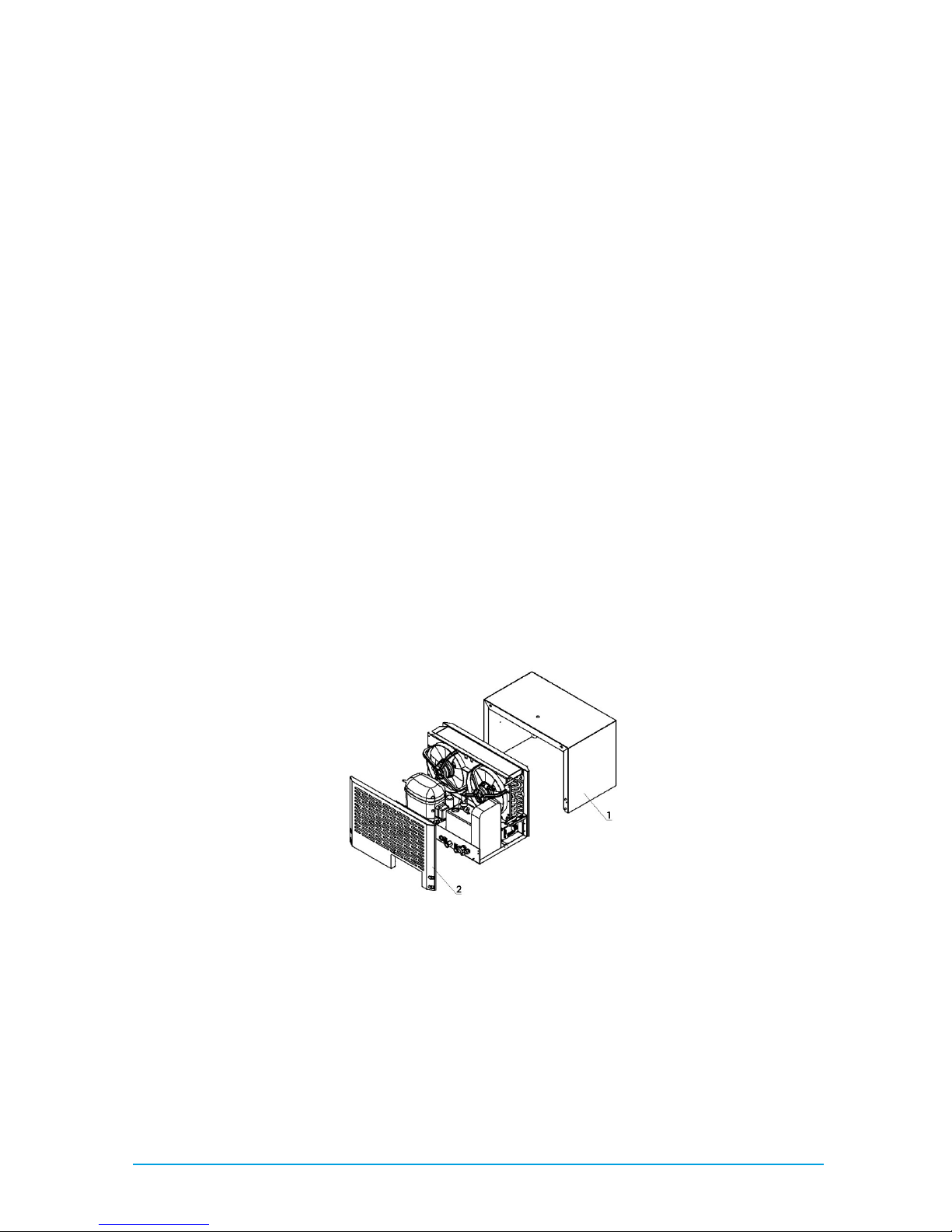
For type nBoxX1.5:
For type nBoxX1.5: For type nBoxX1.5:
For type nBoxX1.5:
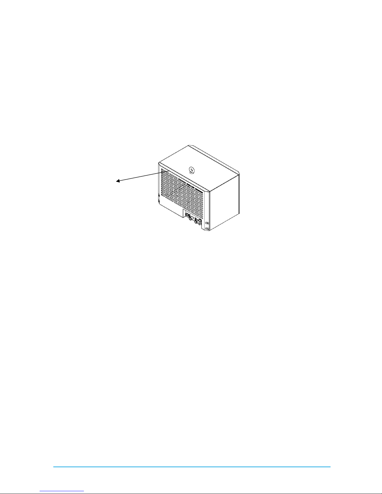
Fig. 7 PLC connection for nBoxX1.5
• Remove the louvered grille (2222) on the rear of the cooling unit.
• Remove the housing (1111).
• Guide a suitable connection cable into the unit via the additional cable gland provided
• Connect the cable to the 15-pole Sub-D socket
 Loading...