

KKT chillers cBoxX 100 Circuit Diagrams
Stromlaufplan / Circuit diagram
Aderkennzeichnung / core identification
Projekt / project
Modell / model:
max. Einschaltstrom / inrush amps:
Betriebsspannung / Line:
Steuerspannung / Control voltage:
Anschlußleistung / Connected load:
max. Stromaufnahme / Max. current:
Schutzart / Prot.class:
Vorsicherung / Main fuse:
Schutzvermerk nach DIN ISO 16016 beachten !
Zur Beachtung !
Der Schaltplan ist Bestandteil des Schaltschrankes gleicher Baunummer und
sollte nicht daraus entfernt werden, damit er im Notfall sofort verfügbar ist.
Bei unbefugten Eingriffen in die Verdrahtung erlischt unsere Gewährleistung !
Vor Inbetriebnahme - alle Schrauben an Schützen,
Klemmen , Relais und Reglern
SCCR:
909100-00468 ab 91001234
cBoxX 100 P 6856
: 155 A
: 460 V / 60Hz
: 24 V DC
: ca. 46,0 kW/ ca. 52,6 kVA
: ca. 66,0 A
: IP 54
: 80 A
: 20 kA
note !
The circuit diagram is an integral part of the switch cabinet, with matching build number.
should not be removed and should always be available on short notice in case of emergency.
Unauthorized changes to the wiring will void the Warranty!
Tighten all screws on contactors,
clamps, relays and controls prior to commissioning.nachziehen.
Drahtfarben / colors of wiring :
Hauptstromkreise / main power : schwarz / black
Schutzleiter / protective conductor : grün-gelb / green-yellow
Steuerspannung / control voltage 24VDC : dunkelblau-darkblue
Steuerspannung / control voltage 24VDC : dunkelblau weiß / darkblue-white
Steuerspannung / control voltage 230 VAC : rot / red
Steuerspannung / control voltage 230VAC (V) : rot-weiß / red-white
Fühlerleitung / sensor conductor: weiß / white
Pot.-freie Verdrahtung / wiring without potential : orange / orange
UL Verdrahtung / UL wiring
Erstellt mit ELCAD/AUCOPLAN (R) 7.11.0
date
editor
change date
R. replacement for: origin:replayement by: KKT
check
normname
28.09.2017
C. Laaber
KKT chillers - a brand of
ait-deutschland GmbH
3 4 5 6 7
cBoxX
cBoxX 100
Art. Nr. 61525501
Deckblatt / cover
sheet
1
sh.
23

1 2 3 4 5 6 7 8
1
DECKBLATT / COVER
2
INHALTSVERZEICHNIS / CONTENS
3
ANSICHT / VIEW
4
AUFB. / VIEW MOUNTING PLATE
5
ANSICHT PLATINE / VIEW PCB
6
EINSPEISUNG / POWER SUPPLY
7
POT. VERTEILER / POWER UNIT
8
DIG. EINGÄNGE / PCB DIG. INPUT
9
DIG. EINGÄNGE / PCB DIG. INPUT
10
DIG. EINGÄNGE / PCB DIG. INPUT
11
DIG. EINGÄNGE / PCB DIG. INPUT
12
DIG. AUSGÄNGE / PCB DIG. OUTPUT
13
DIG. AUSGÄNGE / PCB DIG. OUTPUT
14
DIG. AUSGÄNGE / PCB DIG. OUTPUT
15
ANA. AUSGÄNGE / PCB ANA. INPUT
16
ANA. AUSGÄNGE / PCB ANA. INPUT
17
ANA. AUSGÄNGE / PCB ANA. OUTPUT
18
PLATINE / PCB RESERVE
19
ANA. EINGÄNGE/ PCB ANA. INPUT
20
PUMPE / PUMP
21
KOMPRESSOR / COMPRESSOR
22
LÜFTER / CONDENSER FAN
23
MOTORKLAPPE / MOTOR FLAP
24
SCHNITTSTELLE / INTERFACE
25
Inhaltsverzeichnis /contens
DECKBLATT / COVER C. Laaber
INHALTSVERZEICHNIS / CONTENS C. Laaber
ANSICHT / VIEW C. Laaber
AUFB. PLATTE / VIEW MOUNTING PLATE C. Laaber
ANSICHT PLATINE / VIEW PCB C. Laaber
EINSPEISUNG / POWER SUPPLY C. Laaber
POT. VERTEILER / POWER UNIT C. Laaber
DIG. EINGÄNGE / PCB DIG. INPUT C. Laaber
DIG. EINGÄNGE / PCB DIG. INPUT C. Laaber
DIG. EINGÄNGE / PCB DIG. INPUT C. Laaber
DIG. EINGÄNGE / PCB DIG. INPUT C. Laaber
DIG. AUSGÄNGE / PCB DIG. OUTPUT C. Laaber
DIG. AUSGÄNGE / PCB DIG. OUTPUT C. Laaber
DIG. AUSGÄNGE / PCB DIG. OUTPUT C. Laaber
ANA. AUSGÄNGE / PCB ANA. INPUT C. Laaber
ANA. AUSGÄNGE / PCB ANA. INPUT C. Laaber
MODUL FREE SMC5500/C/S C. Laaber
PLATINE / PCB RESERVE C. Laaber
ANA. EINGÄNGE/ PCB ANA. INPUT C. Laaber
PUMPE / PUMP C. Laaber
KOMPRESSOR / COMPRESSOR C. Laaber
LÜFTER / CONDENSER FAN C. Laaber
MOTORKLAPPE / MOTOR FLAP C. Laaber
SCHNITTSTELLE / INTERFACE
C. Laaber
C. Laaber
Revision
Bemerkung:
drawn with ELCAD (R)
c
b
a
change date
date
editor
check
normname
28.09.2017
C. Laaber
KKT chillers - a brand of
ait - deutschland GmbH
replacement for:replacement by:
origin:
KKT
circuit diagram 909100-00468 ab 91001234
cBoxX
-
Alle Leitungen ohne Querschnittsangabe sind 19 AWG
All lines without cross-sectional specification are 19 AWG
Inhaltsverzeichnis / contens
sheet
sh.
2
23
1 2 3 4 5 6 7 8
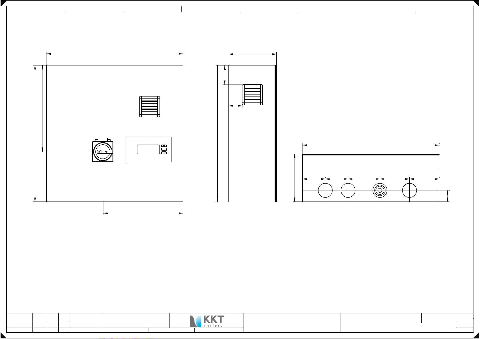
600
210
100
59
415
600
600
600
OK
kkt-chillers.com
210
100 100 140 130 130
50
260
M63 M63 M63 M63
KEL-DPZ 63/13
KEL-DPF 63/23-55
KEL-DPZ 63/13
KEL-DPZ 63/13
drawn with ELCAD (R)
c
b
a
change date
date
editor
check
normname
28.09.2017
C. Laaber
Ansicht Frontseite
view front
KKT chillers - a brand of
ait - deutschland GmbH
Ansicht links
view left
Ansicht unten
view down
Skalierung Maßstab: 1:75
Maßeinheit: mm
Alle Leitungen ohne Querschnittsangabe sind 19 AWG
All lines without cross-sectional specification are 19 AWG
circuit diagram 909100-00468 ab 91001234
cBoxX
replacement for:replacement by:
origin:
KKT
-
Ansicht / view
sheet
sh.
3
23
1 2 3 4 5 6 7 8
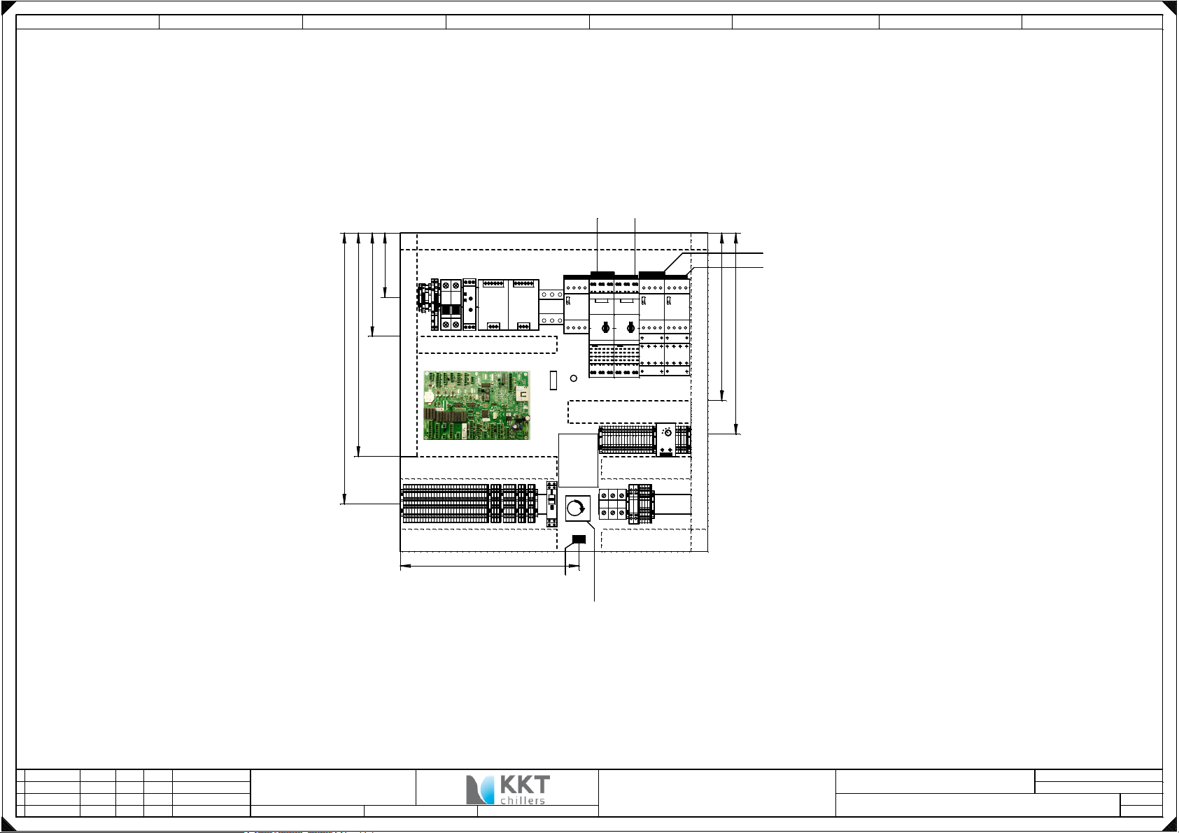
3RV2925-5EB
30x80x490
115
185
400
485
L-
6F2
6F3
7U1
12K1
PE
6A1
6U1
6U2
30x80x250
8A1
30x80x370
Type E
6F1
22F1
PE
Achse 90mm
6Q1
X2
X3 X4
40x80x280 40x80x160
X5 X6
7S1
M !
3RV1915-1BB
20F1 20F2
40x80x220
X1.1
X1.2
PE
PE N
Type E
21F1
12Q1
7B1
21F2
12Q2
XPV+
XPV-
3RV2925-5EB
3RV1915-1AB
Anforderung: Alle Kennzeichen müssen gesondert
unterhalb des Betriebsmittels
angebracht sein!
Requirement : All signs must be mounted
separately below the component
280
360
30x80x500
40x80x280 40x80x160
320
Zugentlastung mit Kabelbinder
strain relief with cable ties
Aufkleber Motor Rechtsdrehfeld
sticker motor right rotary field
drawn with ELCAD (R)
c
b
a
change date
date
editor
check
normname
28.09.2017
C. Laaber
KKT chillers - a brand of
ait - deutschland GmbH
replacement for:replacement by:
origin:
KKT
circuit diagram 909100-00468 ab 91001234
cBoxX
-
Skalierung Maßstab: 1:75
Maßeinheit: mm
Alle Leitungen ohne Querschnittsangabe sind 19 AWG
All lines without cross-sectional specification are 19 AWG
Aufb. Montageplatte / view mounting plate
sheet
sh.
4
23

1 2 3 4 5 6 7 8
600
200
Schaltplantasche
diagram bag
Filter
filter
drawn with ELCAD (R)
c
b
a
change date
date
editor
check
normname
28.09.2017
C. Laaber
600
KKT chillers - a brand of
ait - deutschland GmbH
replacement for:replacement by:
20
250
RJ45 485.3 RJ45 485.2
PE
7N1
Ringkanal L=400 d20
Ansicht Tür innen
view inside of the door
KKT
origin:
d5,5
7E1
245
210
circuit diagram 909100-00468 ab 91001234
cBoxX
-
Skalierung Maßstab: 1:75
Alle Leitungen ohne Querschnittsangabe sind 19 AWG
All lines without cross-sectional specification are 19 AWG
Ansicht Platine / view PCB
Maßeinheit: mm
sheet
sh.
5
23

-6Q1
HLT
125A
Hauptschalter
main switch
Sontheimer
1 2 3 4 5 6 7 8
Kurzschlussfest
short circuit protection
BK
BK
BK
AWG 6
3NW7533-0HG
3NW1020-0HG
-6F1
2 A
12345
phase monitoring relay 6A1 / 21
6
AWG 16
BK
BK
BK
AWG 6
BK
L1.1
L2.1
L3.1
/21.1
/21.1
/21.1
-12Q1
/12.3
-6U1 -6U2
21
-12Q2
22
/12.4
21
22
L1 L2
460 AC
24V-
- +
Netzteil
power supply
Phoenix
Iout / 3,75A
UNO
L1 L2
460 AC
24V-
- +
Netzteil
power supply
Phoenix
Iout / 3,75A
UNO
BK
BK
L1T1
L2
L3
T2
T3
-6A1
L1 L2 L3
Phasenwächter
phase monitoring relay
Siemens 3UG4513-1BR20
141112 242122
-6F2 -6F3
1
C 3A
5SY6103-7
2
C 4A
5SY6104-7
1
2
BL
phase monitoring relay 6A1 / 24
Montageplatte (AWG 6)PE
Tür rechts (AWG 10), Gehäuse (AWG 6)
ST 2,5
-X1
1
ST 2,5
3PE
-X1
4
6PE
BL
La +24V
L+ 24V
L- 24V
L1
/20.1
L2
/20.1
L3
/20.1
/8.6
/7.5
/7.1
/8.6
/7.1
Einspeisung
main power
drawn with ELCAD (R)
c
b
a
change date
date
editor
check
normname
PE
N
USLKG 35N
28.09.2017
C. Laaber
UK 35 BU
122
GN/YE
6W1
152
GN/YE
6W2
USLKG 5
-XN
L-
PE
GN/YE
-6E1
Gehäuseheizung 1
crank case heater 1
KKT chillers - a brand of
ait - deutschland GmbH
-6E2
80W
Gehäuseheizung 2
crank case heater 2
replacement for:replacement by:
80W
Alle Leitungen ohne Querschnittsangabe sind 19 AWG
All lines without cross-sectional specification are 19 AWG
circuit diagram 909100-00468 ab 91001234
origin:
KKT
cBoxX
-
Einspeisung / power supply
sheet
sh.
6
23
/6.8
/6.8
drawn with ELCAD (R)
c
b
a
change date
1 2 3 4 5 6 7 8
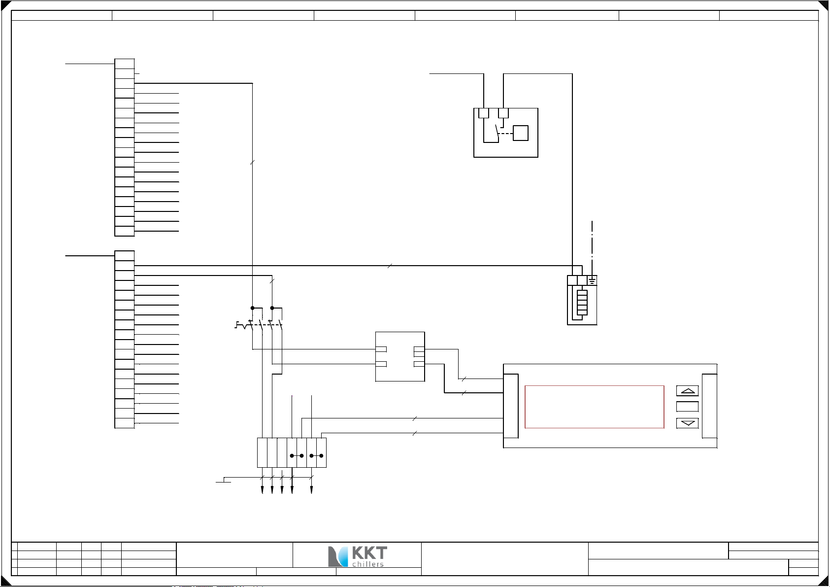
-XPV
PV Verteiler
PV Verteiler
+24V DC
STTB 2,5-TWIN-PV
potential distribution
-24V DC
STTB 2,5-TWIN-PV
potential distribution
date
editor
check
normname
1L+
2L+
3L+
4L+
5L+
6L+
7L+
8L+
9L+
10L+
11L+
12L+
13L+
14L+
15L+
16L+
17L+
18L+
1L2L3L4L5L6L7L8L-
9L10L11L12L13L14L15L16L17L18L-
28.09.2017
C. Laaber
4L+
5L+
6L+
7L+
8L+
9L+
10L+
11L+
12L+
13L+
14L+
15L+
16L+
17L+
18L+
4L5L6L7L8L-
9L10L11L12L13L14L15L16L17L18L-
/8.1
/12.1
/13.1
/13.3
/14.1
/14.3
/14.3
/14.4
/17.3
/18.5
/23.3
/23.3
/8.1
/12.3
/12.3
/14.1
-7S1
/17.3
Umschaltung
/18.5
Fernbedien-
tableau
in / out
/20.3
/20.5
/23.2
STTB 2,5
Ölflex classic 110 CY
5G1
KKT chillers - a brand of
ait - deutschland GmbH
BU
BU/WH
21543
7
1
-X4
223PE
1
EXTERN
Fernbedientableau
Remote control panel
replacement for:replacement by:
EATON S/2WM
IN (I)
OFF (0)
OUT (II)
Platine
RS485-3
/8.34
2 BU
PE
4
La +24V
/6.8
-7B1
1 2
+-
T
Schaltschrankthermostat
Heizen
case-thermostate
heating
/20.6
X1.18
BU/WH
-7E1
-7U1
IN OUT
24V
COM
24VDC/12VDC0,5A
/8.36
3 WH
Wago
859-805
12V
12V
COM
2 = BU
-7N1
+ OG/WH
- GN/WH
RJ45 485.3
L N
Schaltschrankheizung
control box heater
RJ45 485.2
OK
3 = WH
5
7
Betrieb nur mit EINEM Bedienteil möglich
5
operating only with a use in part possible
Intern oder Extern
kkt-chillers.com
Bedientableau
control panel
internal or external
Alle Leitungen ohne Querschnittsangabe sind 19 AWG
All lines without cross-sectional specification are 19 AWG
circuit diagram 909100-00468 ab 91001234
cBoxX
origin:
KKT
-
Pot. Verteiler / power unit 24 V DC
L+ 24V
L- 24V
sheet
sh.
7
23
 Loading...