

Page 1

Installing Instruction
Installing Instruction
Installing InstructionInstalling Instruction
Healthcare chiller of the KSC Series
Healthcare chiller of the KSC Series
Healthcare chiller of the KSC SeriesHealthcare chiller of the KSC Series
Version „Revision 0
Version „Revision 05555”
Version „Revision 0Version „Revision 0
”
” ”
Manufacturer
Manufacturer
ManufacturerManufacturer
ait-deutschland GmbH T +49 9228 9977 0
Industriestraße 3 F +49 9228 9977 149
95359 Kasendorf E info@kkt-chillers.com
Germany W www.kkt-chillers.com
Representative in the US and Service Center
Representative in the US and Service Center
Representative in the US and Service CenterRepresentative in the US and Service Center
KKT chillers, Inc. T 847 734 1600
1280 Landmeier Road F 847 734 1601
Elk Grove TF 866 517 6867
IL 60007 E support@kkt-chillersusa.com
YOUR LOCAL S
YOUR LOCAL SERVICE CONTRACTOR IS:
YOUR LOCAL SYOUR LOCAL S
COMPANY NAME:
PHONE NUMBER: FAX NUMBER:
Type KSC 215
Type KSC 215----LLLL----U/S
Type KSC 215Type KSC 215
ERVICE CONTRACTOR IS:
ERVICE CONTRACTOR IS:ERVICE CONTRACTOR IS:
U/S
U/SU/S
page
page 1111von
page page
von39
39
vonvon
3939
U:\KSC 215 L\03_Dokumente\Installationsanleitung\KKT_chillers_Installing_Instruction_engl_Vers05.doc
Page 2

Installing Instruction
Installing Instruction
Installing InstructionInstalling Instruction
Healthcare chiller of the KSC Series
Healthcare chiller of the KSC Series
Healthcare chiller of the KSC SeriesHealthcare chiller of the KSC Series
Version „Revision 0
Version „Revision 05555”
Version „Revision 0Version „Revision 0
”
” ”
Type KSC 215
Type KSC 215----LLLL----U/S
Type KSC 215Type KSC 215
U/S
U/SU/S
Contents
Contents
ContentsContents
I Technical Data ..................................................................................................................... 4
I. Basics .................................................................................................................................. 5
II. Installation site .................................................................................................................. 7
a) Ambient temperatures ................................................................................................. 7
b) Clearance ...................................................................................................................... 7
c) Servicing and repair access ......................................................................................... 7
d) Air flow .......................................................................................................................... 7
e) Load capacity of the base............................................................................................ 7
III. Transport route/transport ............................................................................................. 10
a) Transport measurements ......................................................................................... 10
b) Transport weight ....................................................................................................... 10
c) Transport safety locks ............................................................................................... 10
d) Crane transport ......................................................................................................... 10
e) Dimensions in inch .................................................................................................... 12
f) Dimensions in mm ..................................................................................................... 13
g) Weights ...................................................................................................................... 14
IV. Power supply/electrical connection ............................................................................ 14
a) Follow local regulations ............................................................................................ 14
b) Voltage, frequency, tolerances ................................................................................. 14
c) Type of cable .............................................................................................................. 14
d) Length and cable width ............................................................................................ 14
e) Strain relief ................................................................................................................ 14
f) Clamps ........................................................................................................................ 15
g) Fuse ............................................................................................................................ 16
h) Phase sequence ........................................................................................................ 16
i) EMC Compatibility and Grounding ............................................................................ 17
j) Data cable ................................................................................................................... 18
V. Interface filter panel (IFP) .............................................................................................. 20
Scope of IFP supply: ...................................................................................................... 21
Installation of IFP ........................................................................................................... 21
VI. Water connection .......................................................................................................... 22
a) Pipe material ............................................................................................................. 22
b) Relation of pipe diameter to distance between chiller and IFP ............................. 22
c) Dimensions of the connections ................................................................................ 22
d) Inflow and outflow ..................................................................................................... 22
e) Water quality ............................................................................................................. 22
f) Glycol........................................................................................................................... 23
g) Filling .......................................................................................................................... 23
h) Vents and air chambers............................................................................................ 23
VII. Initial start-up ............................................................................................................... 27
VIII. SPS Settings ............................................................................................................... 28
IX. Control ............................................................................................................................ 31
a) Pump .......................................................................................................................... 31
page
page 2222von
page page
von39
vonvon
39
3939
U:\KSC 215 L\03_Dokumente\Installationsanleitung\KKT_chillers_Installing_Instruction_engl_Vers05.doc
Page 3

Installing Instruction
Installing Instruction
Installing InstructionInstalling Instruction
Healthcare chiller of the KSC Series
Healthcare chiller of the KSC Series
Healthcare chiller of the KSC SeriesHealthcare chiller of the KSC Series
Version „Revision 0
Version „Revision 05555”
Version „Revision 0Version „Revision 0
”
” ”
Type KSC 215
Type KSC 215----LLLL----U/S
Type KSC 215Type KSC 215
U/S
U/SU/S
b) Water pressures ........................................................................................................ 31
c) Compressor ................................................................................................................ 31
d) Vents .......................................................................................................................... 31
e) Refrigerant pressures ............................................................................................... 31
f) Temperatures ............................................................................................................. 31
X Overview water chiller and IFP ....................................................................................... 32
XI Trouble Shooting ............................................................................................................ 33
XII. Maintenance ................................................................................................................ 38
XIII. Warranty ...................................................................................................................... 38
XIV. Safety Warnings ......................................................................................................... 38
page
page 3333von
page page
von39
vonvon
39
3939
U:\KSC 215 L\03_Dokumente\Installationsanleitung\KKT_chillers_Installing_Instruction_engl_Vers05.doc
Page 4

Installing Instruction
Installing Instruction
Installing InstructionInstalling Instruction
Healthcare chiller of the KSC Series
Healthcare chiller of the KSC Series
Healthcare chiller of the KSC SeriesHealthcare chiller of the KSC Series
Version „Revision 0
Version „Revision 05555”
Version „Revision 0Version „Revision 0
”
” ”
I
I Technical Data
Technical Data
I I
Technical DataTechnical Data
Model Outdoor
Dimensions Depth 940 mm
Width 3040 mm
Height 1850 mm
Weight without refrigerant load ca. 1066 kg
Weight with load ca. 1090 kg
Shipping weight ca. 1600 kg
Weight total refrigerant load 24.0 kg
Quantity of air 2x 18000 m³/h
Number of fans 4
Refrigerant R134a
Required quantity of refrigerant 2x12kg
High-pressure switch 19 bar
Water connection inlet internal 2“ G" female thread
Water connection outlet internal 2“ G" femalethread
Cold water temperature outlet min. 19-22 °C ±0.5 K
Cold water temperature inlet max. 30 °C
Primary water pump type 60Hz CR 10 - 05
Primary water pump type 50Hz CR 10 - 07
Rated water capacity min. 7.8 m³/h
Rated water pressure 6.5 bar
Ambient temperature min.-20 °C
max.+48 °C
Cooling capacity 60.0 kW
Rated cold water outlet temperature 20 °C
Temperature of surroundings 48 °C
Main supply 380-480 V / 3Ph / 50-60 Hz
Control voltage 24 VDc
Fluctuations in main voltage max. -14+10 %
Fluctuations in frequency max. ±1 Hz
Power input max. 29 kW
Noise level at 5 m max.68 db(A)
at max cooling capacity and max. ambient temperature
Type KSC 215
Type KSC 215----LLLL----U/S
Type KSC 215Type KSC 215
U/S
U/SU/S
page
page 4444von
page page
von39
39
vonvon
3939
U:\KSC 215 L\03_Dokumente\Installationsanleitung\KKT_chillers_Installing_Instruction_engl_Vers05.doc
Page 5

Installing Instruction
Installing Instruction
Installing InstructionInstalling Instruction
Healthcare chiller of the KSC Series
Healthcare chiller of the KSC Series
Healthcare chiller of the KSC SeriesHealthcare chiller of the KSC Series
Version „Revision 0
Version „Revision 05555”
Version „Revision 0Version „Revision 0
”
” ”
Type KSC 215
Type KSC 215----LLLL----U/S
Type KSC 215Type KSC 215
U/S
U/SU/S
page
page 5555von
page page
I. Basics
I. Basics
I. BasicsI. Basics
Scope of Chiller supply:
-KSC215-L-…
-Installing Instruction inside the switch cabinet
-Manual inside the switch cabinet
-Data transfere cable 50m (164feet) in a box near the pump
-Short data transfere cable in a box near the pump
-Grounding in a box near the pump
-Overvoltage protection in a box near the pump
-Spare parts in a box near the pump
-Brass fittings for the connection Chiller inlet/outlet and piping (on the pump)
-Stainless steel fittings for the connetion piping and IFP (on the pump)
Carefully read the operating instructions located in the control cabinet before beginning
installation.
Check the equipment for damage on arrival and report any defects immediately.
Claims submitted later cannot be honored.
Please observe the following notes and warnings.
1. Removing the operating instructions from the cooling block voids the warranty!
von39
39
vonvon
3939
2. The volume of the water circulation system of the cooling block is approx. 17 liters
(~4.5 gal) Please consider this by filling the water system with water ethylene
glycol mixture.
3. Always operate the water circulation system at a volume of 35-38% ethylene
glycol.
This is regardless of the ambient temperature.
Non-compliance voids the warranty.
Use of automobile anti-freeze and propylene glycol is prohibited.
Fill with clean water (potable water quality) with Ethylene-glycol at the rate of min.
35% to max. 38%.
Use ethylene-glycol of only one manufacturer.
(e.g.: DOWTHERM SR1-Dow Chemical, Safeflow EG-Clariant)
Do not mix two ore more different manufacturer for one water-ethylene-glycol
circuit.
Open front panel and fill to a pressure of min.1,5 bar via the feed cock when the
pump is off.
U:\KSC 215 L\03_Dokumente\Installationsanleitung\KKT_chillers_Installing_Instruction_engl_Vers05.doc
Page 6

Installing Instruction
Installing Instruction
Installing InstructionInstalling Instruction
Healthcare chiller of the KSC Series
Healthcare chiller of the KSC Series
Healthcare chiller of the KSC SeriesHealthcare chiller of the KSC Series
Version „Revision 0
Version „Revision 05555”
Version „Revision 0Version „Revision 0
”
” ”
Type KSC 215
Type KSC 215----LLLL----U/S
Type KSC 215Type KSC 215
U/S
U/SU/S
After filling, check all connections for leakage.
4. With the pump turned off, fill the system to a static water pressure of 1.5 bar
(21.75 psi) by Avanto an Chiller at the same level. (Also see Table 1 page24)
(Also see Table 1 page24)
(Also see Table 1 page24) (Also see Table 1 page24)
5. The cooling block operates completely independently of the MR system.
6. Voltage is still present in the KSC control cabinet when the MR system is turned
off. Risk of death!
Risk of death!
Risk of death!Risk of death!
7. Even with the cooling block turned off, high surface temperatures can cause
burns. Risk of death!
Risk of death!
Risk of death!Risk of death!
Only trained and qualified personnel are permitted to install, start up, and repair the
cooling block.
page
page 6666von
page page
von39
vonvon
39
3939
U:\KSC 215 L\03_Dokumente\Installationsanleitung\KKT_chillers_Installing_Instruction_engl_Vers05.doc
Page 7

Installing Instruction
Installing Instruction
Installing InstructionInstalling Instruction
Healthcare chiller of the KSC Series
Healthcare chiller of the KSC Series
Healthcare chiller of the KSC SeriesHealthcare chiller of the KSC Series
Version „Revision 0
Version „Revision 05555”
Version „Revision 0Version „Revision 0
II. Installation site
II. Installation site
II. Installation siteII. Installation site
a) Ambient temperatures
a) Ambient temperatures
a) Ambient temperaturesa) Ambient temperatures
The chiller is designed to operate at ambient temperatures between –20°C (-4°F)
minimum and +48°C (+118.4°F) maximum.
Malfunctions can occur outside these specifications.
If the chiller is used at high ambient temperatures (higher than 40°C = 104°F) the the
If the chiller is used at high ambient temperatures (higher than 40°C = 104°F) the the
If the chiller is used at high ambient temperatures (higher than 40°C = 104°F) the the If the chiller is used at high ambient temperatures (higher than 40°C = 104°F) the the
chiller should be installed that the
chiller should be installed that the switch cabinet is not fully exposed to the sun
chiller should be installed that the chiller should be installed that the
radiation when the maximum ambient temperature is prevent. If th
radiation when the maximum ambient temperature is prevent. If this is not possible
radiation when the maximum ambient temperature is prevent. If thradiation when the maximum ambient temperature is prevent. If th
please install a sun protection!!
please install a sun protection!!
please install a sun protection!! please install a sun protection!!
Support from KKT
Support from KKT chillers
Support from KKTSupport from KKT
”
” ”
chillers could be requested.
chillerschillers
Type KSC 215
Type KSC 215----LLLL----U/S
Type KSC 215Type KSC 215
could be requested.
could be requested.could be requested.
U/S
U/SU/S
switch cabinet is not fully exposed to the sun
switch cabinet is not fully exposed to the sun switch cabinet is not fully exposed to the sun
is is not possible
is is not possible is is not possible
page
page 7777von
page page
von39
vonvon
39
3939
b) Clearance
b) Clearance
b) Clearanceb) Clearance
Maintain at least 100 cm (39.4 in.) around all four sides of the chiller for air intake and
servicing/repair.
Under no circumstances install a roof above the chiller.
c) Servicing and repair access
c) Servicing and repair access
c) Servicing and repair accessc) Servicing and repair access
See Clearance
d) Air flow
d) Air flow
d) Air flowd) Air flow
Never obstruct the air intake to the condensers on the upper third of the chiller.
The diameter of the tubes may not be smaller than the size specified.
e) Load capacity
e) Load capacity of the base
e) Load capacitye) Load capacity
Verify that the installation surface has sufficient load capacity.
A concrete foundation or sectional steel construction is recommended.
A concrete foundation needs to be 200 mm (7.8 in.) wider and 200 mm (7.8 in.) longer
than the cooling block. Final dimensions: approx. 3,200 mm (10.5 feet) long by 1,100
mm (3.6 ft) wide.
The operating weight of the chiller is approx. 1,100 kg (2,425 lbs.).
The operating weight of the chiller is approx. 1,100 kg (2,425 lbs.).
The operating weight of the chiller is approx. 1,100 kg (2,425 lbs.).The operating weight of the chiller is approx. 1,100 kg (2,425 lbs.).
It is important that the cooling block be installed on a level surface.
of the base
of the baseof the base
U:\KSC 215 L\03_Dokumente\Installationsanleitung\KKT_chillers_Installing_Instruction_engl_Vers05.doc
Page 8

Installing Instruction
Installing Instruction
Installing InstructionInstalling Instruction
Healthcare chiller of the KSC Series
Healthcare chiller of the KSC Series
Healthcare chiller of the KSC SeriesHealthcare chiller of the KSC Series
Version „Revision 0
Version „Revision 05555”
Version „Revision 0Version „Revision 0
”
” ”
Type KSC 215
Type KSC 215----LLLL----U/S
Type KSC 215Type KSC 215
U/S
U/SU/S
page
page 8888von
page page
von39
39
vonvon
3939
U:\KSC 215 L\03_Dokumente\Installationsanleitung\KKT_chillers_Installing_Instruction_engl_Vers05.doc
Page 9

Installing Instruction
Installing Instruction
Installing InstructionInstalling Instruction
Healthcare chiller of the KSC Series
Healthcare chiller of the KSC Series
Healthcare chiller of the KSC SeriesHealthcare chiller of the KSC Series
Version „Revision 0
Version „Revision 05555”
Version „Revision 0Version „Revision 0
”
” ”
Type KSC 215
Type KSC 215----LLLL----U/S
Type KSC 215Type KSC 215
U/S
U/SU/S
page
page 9999von
page page
von39
39
vonvon
3939
U:\KSC 215 L\03_Dokumente\Installationsanleitung\KKT_chillers_Installing_Instruction_engl_Vers05.doc
Page 10

Installing Instruction
Installing Instruction
Installing InstructionInstalling Instruction
Healthcare chiller of the KSC Series
Healthcare chiller of the KSC Series
Healthcare chiller of the KSC SeriesHealthcare chiller of the KSC Series
Version „Revision 0
Version „Revision 05555”
Version „Revision 0Version „Revision 0
III. Transport r
III. Transport route/transport
III. Transport rIII. Transport r
a) Transport measurements
a) Transport measurements
a) Transport measurementsa) Transport measurements
Length: approx. 3,200 mm (126 inches)
Width: approx. 1,100mm (43.3 inches)
Height: approx. 2,150mm (approx. 84.65 inches)
You also need to add the height of the transport equipment, such as pallets, lift truck,
transport rollers, etc.
”
” ”
oute/transport
oute/transportoute/transport
Type KSC 215
Type KSC 215----LLLL----U/S
Type KSC 215Type KSC 215
U/S
U/SU/S
page
page 10
10von
page page
1010
von39
39
vonvon
3939
b) Transport weight
b) Transport weight
b) Transport weightb) Transport weight
Weight: approx. 1,600 kg (approx. 3,528 lbs.)
c) Transport safety locks
c) Transport safety locks
c) Transport safety locksc) Transport safety locks
There are no transport safety locks to remove.
d) Crane transport
d) Crane transport
d) Crane transportd) Crane transport
If a crane will be used to transport the chiller, note the following:
Lift the chiller only from its base. Insert two steel rods through the holes in the base.
The rods must be specifically designed for this purpose and able to support the weight
(1,100 kg./2,425 lbs.).
Secure the rods with locking pins to prevent shifting.
Use only straps or rope for lifting from the rods.
The straps or ropes must be held in place with a frame to keep them from pressing into
the side walls, gutters, and condenser body. (Refer to the following graphic).
U:\KSC 215 L\03_Dokumente\Installationsanleitung\KKT_chillers_Installing_Instruction_engl_Vers05.doc
Page 11

Installing Instruction
Installing Instruction
Installing InstructionInstalling Instruction
Healthcare chiller of the KSC Series
Healthcare chiller of the KSC Series
Healthcare chiller of the KSC SeriesHealthcare chiller of the KSC Series
Version „Revision 0
Version „Revision 05555”
Version „Revision 0Version „Revision 0
”
” ”
Type KSC 215
Type KSC 215----LLLL----U/S
Type KSC 215Type KSC 215
U/S
U/SU/S
page
page 11
page page
11von
von39
1111
vonvon
39
3939
U:\KSC 215 L\03_Dokumente\Installationsanleitung\KKT_chillers_Installing_Instruction_engl_Vers05.doc
Page 12

Installing Instruction
Installing Instruction
Installing InstructionInstalling Instruction
Healthcare chiller of the KSC Series
Healthcare chiller of the KSC Series
Healthcare chiller of the KSC SeriesHealthcare chiller of the KSC Series
Version „Revision 0
Version „Revision 05555”
Version „Revision 0Version „Revision 0
”
” ”
e)
e) Dimensions in inch
Dimensions in inch
e) e)
Dimensions in inchDimensions in inch
Type KSC 215
Type KSC 215----LLLL----U/S
Type KSC 215Type KSC 215
U/S
U/SU/S
page
page 12
page page
12von
von39
1212
vonvon
39
3939
U:\KSC 215 L\03_Dokumente\Installationsanleitung\KKT_chillers_Installing_Instruction_engl_Vers05.doc
Page 13

Installing Instruction
Installing Instruction
Installing InstructionInstalling Instruction
Healthcare chiller of the KSC Series
Healthcare chiller of the KSC Series
Healthcare chiller of the KSC SeriesHealthcare chiller of the KSC Series
Version „Revision 0
Version „Revision 05555”
Version „Revision 0Version „Revision 0
”
” ”
f)
f) Dimensions in mm
Dimensions in mm
f) f)
Dimensions in mmDimensions in mm
Type KSC 215
Type KSC 215----LLLL----U/S
Type KSC 215Type KSC 215
U/S
U/SU/S
page
page 13
page page
13von
von39
1313
vonvon
39
3939
U:\KSC 215 L\03_Dokumente\Installationsanleitung\KKT_chillers_Installing_Instruction_engl_Vers05.doc
Page 14

Installing Instruction
Installing Instruction
Installing InstructionInstalling Instruction
Healthcare chiller of the KSC Series
Healthcare chiller of the KSC Series
Healthcare chiller of the KSC SeriesHealthcare chiller of the KSC Series
Version „Revision 0
Version „Revision 05555”
Version „Revision 0Version „Revision 0
g) Weights
g) Weights
g) Weightsg) Weights
Net weight: 1,060 kg. (2,337 lbs.)
Operating weight: approx. 1,100 kg. (2,425 lbs.)
Transport weight: approx. 1,600 kg (3,527.4 lbs.)
Refrigerant: approx. 2 X 12 kg. (26.45 lbs.) R 134a
”
” ”
Type KSC 215
Type KSC 215----LLLL----U/S
Type KSC 215Type KSC 215
U/S
U/SU/S
page
page 14
page page
14von
von39
1414
vonvon
39
3939
IV. Power supply/ele
IV. Power supply/electrical connection
IV. Power supply/eleIV. Power supply/ele
a) Follow local regulations
a) Follow local regulations
a) Follow local regulationsa) Follow local regulations
Strictly adhere to the regulations of the local power company and authorities. Only
trained, authorized persons are permitted to connect the power.
b) Voltage, frequency, tolerances
b) Voltage, frequency, tolerances
b) Voltage, frequency, tolerancesb) Voltage, frequency, tolerances
Voltage range: 380 - 480 Volt –14%+10%
Frequency range: 50 – 60Hz +/-1Hz
c) Type of cable
c) Type of cable
c) Type of cablec) Type of cable
Make sure to use appropriately designed and approved cables when routing.
d) Length and cable width
d) Length and cable width
d) Length and cable widthd) Length and cable width
A cable width of at least 16mm² per phase is required for cables up to 50 meters (164
ft.) in length.
Therefore, a 5 x 16mm² cable is required.
ctrical connection
ctrical connectionctrical connection
e) Strain relief
e) Strain relief
e) Strain reliefe) Strain relief
The input cable must be fitted on both sides with a strain relief.
U:\KSC 215 L\03_Dokumente\Installationsanleitung\KKT_chillers_Installing_Instruction_engl_Vers05.doc
Page 15

Installing Instruction
Installing Instruction
Installing InstructionInstalling Instruction
Healthcare chiller of the KSC Series
Healthcare chiller of the KSC Series
Healthcare chiller of the KSC SeriesHealthcare chiller of the KSC Series
Version „Revision 0
Version „Revision 05555”
Version „Revision 0Version „Revision 0
”
” ”
Type KSC 215
Type KSC 215----LLLL----U/S
Type KSC 215Type KSC 215
U/S
U/SU/S
page
page 15
page page
f) Clamps
f) Clamps
f) Clampsf) Clamps
Insert the input cable through the cable feed-through (see photograph) next to the
water connections. Route it into the control cabinet through the cable channel installed
on the back of the control cabinet.
15von
von39
1515
vonvon
39
3939
Use the clamps to secure the routed cable (see photograph).
Attention!!
Do not pass the power supply line across the switch cabinet!!
Use cable opening in the lower right hand side of cabinet!!
Drilling holes into and running cables into the cabinet can cause interferences with the
regulation electronics!!
U:\KSC 215 L\03_Dokumente\Installationsanleitung\KKT_chillers_Installing_Instruction_engl_Vers05.doc
Page 16

Installing Instruction
Installing Instruction
Installing InstructionInstalling Instruction
Healthcare chiller of the KSC Series
Healthcare chiller of the KSC Series
Healthcare chiller of the KSC SeriesHealthcare chiller of the KSC Series
Version „Revision 0
Version „Revision 05555”
Version „Revision 0Version „Revision 0
”
” ”
Type KSC 215
Type KSC 215----LLLL----U/S
Type KSC 215Type KSC 215
U/S
U/SU/S
page
page 16
page page
g) Fuse
g) Fuse
g) Fuseg) Fuse
Maximum 60 A slow-blowing fuse for pre-fusing.
Maximum overcurrent of 200 A for 50 msec.
h) Phase sequence
h) Phase sequence
h) Phase sequenceh) Phase sequence
Observe the correct phase sequence when routing the wires, otherwise the cooling
block will not start. A phase sequence relay (5A1) is installed for this purpose.
The monitoring relay has ist own power supply, measured voltage = supply voltage.
The relay monitors the phase sequence an the phase failureof one of the three phases
in a 3-phase network. No settings are necessary.
When the line voltage is switched on, the green LED lights up. IF the correct phase
sequence is applied to the terminals L1-L2-L3, the output relay picks up.
If the wrong phase sequence is applied, the red LED blinks an the output relay does not
pick up. If a phase failure occurs, the red LED lights up an the output relay drops out.
Attention: The red LED is an error diagnosis indicator an does not show the current
state of the relay.
16von
von39
1616
vonvon
39
3939
U:\KSC 215 L\03_Dokumente\Installationsanleitung\KKT_chillers_Installing_Instruction_engl_Vers05.doc
Page 17

Installing Instruction
Installing Instruction
Installing InstructionInstalling Instruction
Healthcare chiller of the KSC Series
Healthcare chiller of the KSC Series
Healthcare chiller of the KSC SeriesHealthcare chiller of the KSC Series
Version „Revision 0
Version „Revision 05555”
Version „Revision 0Version „Revision 0
”
” ”
Type KSC 215
Type KSC 215----LLLL----U/S
Type KSC 215Type KSC 215
U/S
U/SU/S
page
page 17
page page
i) EMC Compatibility and Grounding
i) EMC Compatibility and Grounding
i) EMC Compatibility and Groundingi) EMC Compatibility and Grounding
This comments are compiled to help the field electrician to install the grounding of the
power supply and to get a EMC Compatibility.
All electrical equipment produces radio and line-borne interference at various
frequencies. The cables pass this on to the environment like an aerial.
The basic countermeasures are isolation of the wiring of control and power components,
proper grounding and shielding of cables.
A large contact area is necessary for low-impedance grounding of HF interference. The
use of grounding straps instead of cables is therefore definitely advisable.
Moreover, cable shields must be
connected with purpose-made ground
clips.
The grounding surface must be highly
conductive bare metal. Remove any
coats of varnish and paint.
The width of the grounding wire must be min. 16mm² (AWG 6) or of the same width of the
power supply.
The grounding must be an isolated ground and must connected on the ground terminal
(X1) in the switch cabinet. The ground resistance must be less than 10 Ohm.
Metal cable conduits are not allowed for grounding.
The piping of the chiller (supply and return) have to be grounded too.
Do not share the ground wire with other devices.
Always use a ground wire that complies with technical standards on electrical equipment
and minimize the length of the ground wire.
When using more than one Inverter, be careful not to loop the ground wire.
(e.g. a CT-Chiller KPC108-L-U/S stands near an Avanto-Chiller KSC215-L-U/S)
17von
von39
1717
vonvon
39
3939
U:\KSC 215 L\03_Dokumente\Installationsanleitung\KKT_chillers_Installing_Instruction_engl_Vers05.doc
Page 18

Installing Instruction
Installing Instruction
Installing InstructionInstalling Instruction
Healthcare chiller of the KSC Series
Healthcare chiller of the KSC Series
Healthcare chiller of the KSC SeriesHealthcare chiller of the KSC Series
Version „Revision 0
Version „Revision 05555”
Version „Revision 0Version „Revision 0
”
” ”
Type KSC 215
Type KSC 215----LLLL----U/S
Type KSC 215Type KSC 215
U/S
U/SU/S
j) Data cable
j) Data cable
j) Data cablej) Data cable
Attach the “X8 Chiller” end of the 16-pin data cable (included) to the green connector
(see photograph) at the top right of the control cabinet.
page
page 18
18von
page page
1818
von39
39
vonvon
3939
Power plug
A separate feed-through for the power plug is located on the right wall of the control
cabinet (see photograph).
U:\KSC 215 L\03_Dokumente\Installationsanleitung\KKT_chillers_Installing_Instruction_engl_Vers05.doc
Page 19

Installing Instruction
Installing Instruction
Installing InstructionInstalling Instruction
Healthcare chiller of the KSC Series
Healthcare chiller of the KSC Series
Healthcare chiller of the KSC SeriesHealthcare chiller of the KSC Series
Version „Revision 0
Version „Revision 05555”
Version „Revision 0Version „Revision 0
”
” ”
Type KSC 215
Type KSC 215----LLLL----U/S
Type KSC 215Type KSC 215
U/S
U/SU/S
Feed-through
• Run the cable from the chiller to the MR electronic cabinets.
• Connect the lightning arrester with the 164 ft / 50 m data cable.
• Connect the short data cable with the lightning arrester.
• Attach the other end of the short data cable on the electronics cabinet ACC X81 of
the MR system.
• Connect the grounding wire.
page
page 19
19von
page page
1919
von39
39
vonvon
3939
U:\KSC 215 L\03_Dokumente\Installationsanleitung\KKT_chillers_Installing_Instruction_engl_Vers05.doc
Page 20

Installing Instruction
Installing Instruction
Installing InstructionInstalling Instruction
Healthcare chiller of the KSC Series
Healthcare chiller of the KSC Series
Healthcare chiller of the KSC SeriesHealthcare chiller of the KSC Series
Version „Revision 0
Version „Revision 05555”
Version „Revision 0Version „Revision 0
”
” ”
Type KSC 215
Type KSC 215----LLLL----U/S
Type KSC 215Type KSC 215
U/S
U/SU/S
page
page 20
page page
20von
von39
2020
vonvon
39
3939
U:\KSC 215 L\03_Dokumente\Installationsanleitung\KKT_chillers_Installing_Instruction_engl_Vers05.doc
.
Page 21

Installing Instruction
Installing Instruction
Installing InstructionInstalling Instruction
Healthcare chiller of the KSC Series
Healthcare chiller of the KSC Series
Healthcare chiller of the KSC SeriesHealthcare chiller of the KSC Series
Version „Revision 0
Version „Revision 05555”
Version „Revision 0Version „Revision 0
”
” ”
Interface filter panel (IFP)
Scope of IFP supply:
Scope of IFP supply:
Scope of IFP supply:Scope of IFP supply:
Data transfer cable (164 ft / 50 m)
Lightning arrester
Short data cable
Grounding wire
Power cable (IFP – compressor)
Water hoses (IFP – compressor)
Dummy plugs
Installation of IFP
Installation of IFP
Installation of IFPInstallation of IFP
To Chiller
Type KSC 215
Type KSC 215----LLLL----U/S
Type KSC 215Type KSC 215
U/S
U/SU/S
Air bleeder
page
page 21
page page
21von
von39
2121
vonvon
39
3939
From Chiller
Attach the IFP to the wall. Contact the project manager for the location provided.
The outflow port of IFP to the MR electronic cabinet and the inflow port from the MR
electronic cabinet can be closed with dummy plugs.
The dummy plugs allows filling the chiller and the IFP with water/ethylene glycol mixture
without MR electronic cabinets connected to IFP.
Water hoses from IFP to the MR electronic cabinets are delivered with the MR system.
U:\KSC 215 L\03_Dokumente\Installationsanleitung\KKT_chillers_Installing_Instruction_engl_Vers05.doc
Page 22

Installing Instruction
Installing Instruction
Installing InstructionInstalling Instruction
Healthcare chiller of the KSC Series
Healthcare chiller of the KSC Series
Healthcare chiller of the KSC SeriesHealthcare chiller of the KSC Series
Version „Revision 0
Version „Revision 05555”
Version „Revision 0Version „Revision 0
VI. Water connection
VI. Water connection
VI. Water connectionVI. Water connection
a) Pipe material
a) Pipe material
a) Pipe materiala) Pipe material
Use only the following materials for the pipes:
1. Copper is recommended
2. Stainless steel
3. PE or PVC – ensure that the appropriate steps are taken to protect the pipe along its
length.
The proper way to seal the European fittings can be done with any of following steps.
1. Pipe sealing cord. There are a number of brands available, however we use Loctite
55
2. Teflon Tape and a Anaerobic sealant.
3. Teflon Tape an Nylog sealant.
As with any sealant, the application instruction must be followed for proper use.
”
” ”
Type KSC 215
Type KSC 215----LLLL----U/S
Type KSC 215Type KSC 215
U/S
U/SU/S
page
page 22
page page
22von
von39
2222
vonvon
39
3939
b) Relation of pipe diameter to distance between chiller and IFP
b) Relation of pipe diameter to distance between chiller and IFP
b) Relation of pipe diameter to distance between chiller and IFPb) Relation of pipe diameter to distance between chiller and IFP
Use 2” (R2, DN 50 or 54-mm copper) for up to 25 meters (82 ft.) of straight pipe.
Use 2 ½” (R21/2, DN 65 or 64-mm copper) for up to 45 meters (147.6 ft.) of straight
pipe.
For distances exceeding 45 meters (147.6 ft.) of straight pipe, e-mail the
actual pipe length, the difference in height, and the required pipe elbows to
KKT: info@kkt-chillers.com
)
c) Dimensions of the connections
c) Dimensions of the connections
c) Dimensions of the connectionsc) Dimensions of the connections
Both the coolant return (water/ethylene glycol mix) from the IFP and the coolant supply
(water/ethylene glycol) to the IFP need to have a 2” internal thread.
To connect them, use a crossover with a 2” external screw thread or preferably a fitting
with a 2” external screw thread (two crossovers are attached to the pump).
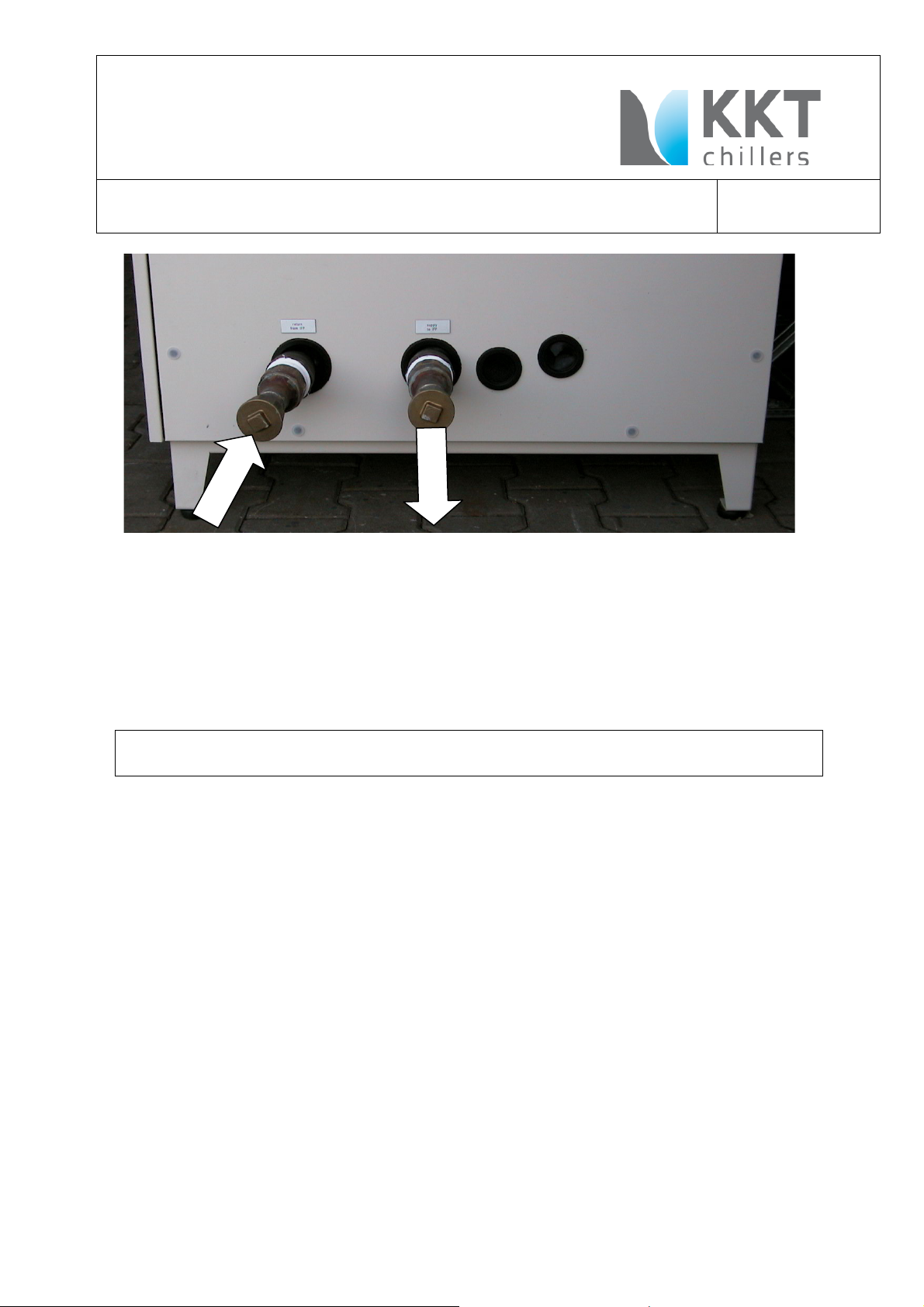
d) Inflow and outflow
d) Inflow and outflow
d) Inflow and outflowd) Inflow and outflow
Verify that the inflow and outflow pipes are attached correctly (do not confuse).
The inflow is FROM the IFP.
The outflow is TO the IFP.
The connections are labeled (see photograph).
On the Chiller inflow and outflow use the brass-fittings.
On the IFP use the stainless steel fittings.
e) Water quality
e) Water quality
e) Water qualitye) Water quality
Use only distilled water to fill the system
U:\KSC 215 L\03_Dokumente\Installationsanleitung\KKT_chillers_Installing_Instruction_engl_Vers05.doc
Page 23
Installing Instruction
Installing Instruction
Installing InstructionInstalling Instruction
Healthcare chiller of the KSC Series
Healthcare chiller of the KSC Series
Healthcare chiller of the KSC SeriesHealthcare chiller of the KSC Series
Version „Revision 0
Version „Revision 05555”
Version „Revision 0Version „Revision 0
”
” ”
Type KSC 215
Type KSC 215----LLLL----U/S
Type KSC 215Type KSC 215
U/S
U/SU/S
page
page 23
page page
23von
von39
2323
vonvon
39
3939
f) Glycol
f) Glycol
f) Glycolf) Glycol
For transport the chiller is empty. The volume which is to consider for the water
ethyleneglycol mixture is approx. 17 liters (~4.5 gal.).
35-38% of the whole volume of watercircuit must be filled with ethylene glycol..
Never use automobile anti-freeze or propylene glycol.
The contractor who fills the water circuit has to supply 30 liters (7.9 gal.) of
The contractor who fills the water circuit has to supply 30 liters (7.9 gal.) of distilled
The contractor who fills the water circuit has to supply 30 liters (7.9 gal.) of The contractor who fills the water circuit has to supply 30 liters (7.9 gal.) of
water
water----ethylene glycol mixture (
waterwater
ethylene glycol mixture (35
ethylene glycol mixture (ethylene glycol mixture (
35----38
3535
38% ethylene glycol) for service.
% ethylene glycol) for service.
3838
% ethylene glycol) for service. % ethylene glycol) for service.
distilled
distilled distilled
Fill with clean water (distilled water quality) with Ethylene-glycol at the rate of min. 35%
to max. 38%.
Use ethylene-glycol of only one manufacturer.
(e.g.: DOWTHERM SR1-Dow Chemical, Safeflow EG-Clariant)
Do not mix two ore more different manufacturer for one water-ethylene-glycol circuit.
Open front panel and fill to a pressure of min.1,5 bar via the feed cock when the pump
is off.
After filling, check all connections for leakage.
g) Filling
g) Filling
g) Fillingg) Filling
For filling, use the fill and drain valve near the pump.
It is best to fill the circulation system completely for the air to escape most easily (refer
to the following item).
open the valves on the IFP
h) Vents and air chambers
h) Vents and air chambers
h) Vents and air chambersh) Vents and air chambers
Be sure to avoid air pockets when routing the pipes.
Air chambers or automatic vents must be attached at the highe
Air chambers or automatic vents must be attached at the highest point to ensure the
Air chambers or automatic vents must be attached at the higheAir chambers or automatic vents must be attached at the highe
most simple and reliable venting procedure
most simple and reliable venting procedure.
most simple and reliable venting proceduremost simple and reliable venting procedure
U:\KSC 215 L\03_Dokumente\Installationsanleitung\KKT_chillers_Installing_Instruction_engl_Vers05.doc
st point to ensure the
st point to ensure the st point to ensure the
Page 24

Installing Instruction
Installing Instruction
Installing InstructionInstalling Instruction
Healthcare chiller of the KSC Series
Healthcare chiller of the KSC Series
Healthcare chiller of the KSC SeriesHealthcare chiller of the KSC Series
Version „Revision 0
Version „Revision 05555”
Version „Revision 0Version „Revision 0
”
” ”
Type KSC 215
Type KSC 215----LLLL----U/S
Type KSC 215Type KSC 215
U/S
U/SU/S
Perform and repeat the following steps until all the air has been bled from the system.
This steps have to be done during the first start up and after
This steps have to be done during the first start up and after each
This steps have to be done during the first start up and afterThis steps have to be done during the first start up and after
components with
components with water inside also Siemens components.
components with components with
water inside also Siemens components.
water inside also Siemens components.water inside also Siemens components.
each replacement of
replacement of
eacheach
replacement of replacement of
page
page 24
24von
page page
2424
von39
39
vonvon
3939
U:\KSC 215 L\03_Dokumente\Installationsanleitung\KKT_chillers_Installing_Instruction_engl_Vers05.doc
Page 25
Installing Instruction
Installing Instruction
Installing InstructionInstalling Instruction
Healthcare chiller of the KSC Series
Healthcare chiller of the KSC Series
Healthcare chiller of the KSC SeriesHealthcare chiller of the KSC Series
Version „Revision 0
Version „Revision 05555”
Version „Revision 0Version „Revision 0
”
” ”
Type KSC 215
Type KSC 215----LLLL----U/S
Type KSC 215Type KSC 215
U/S
U/SU/S
1. From the lowest point possible, fill the pipe with water/ethylene glycol mixture until
no more air escapes from the vent (at the highest point).
Fill the centrifugal pump with the water/ethylene glycol mixture and vent. Close the
vent.
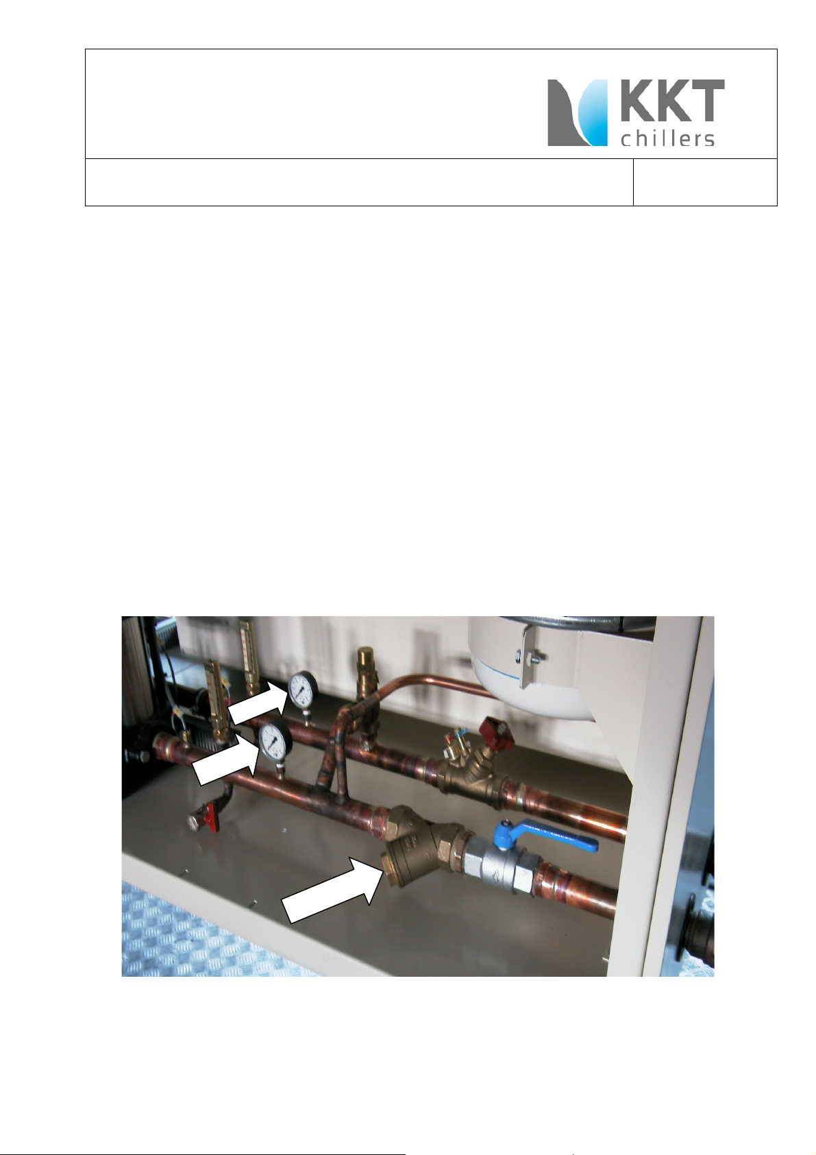
2. Continue filling until the pressure on the water circulation manometers display 1.5
bar (21.75 PSI) with the pump OFF
OFF.
OFFOFF
3. Turn on the pump for 15 seconds and turn it off again.
4. Open the vents on the air chambers and the pump and vent off the remaining air.
The pressure on the manometers drops.
5. Fill again until the pressure on the manometers with the pump OFF
OFF reaches 1.5 bar
OFF OFF
(21.75 PSI).
6. Repeat starting with step 3 until no more air escapes from the vents and the static
pressure with the pump off does not drop below 1.5 bar (21.75 PSI).
7. Clean the filter during the next-to-the-last pass.
8. If the pressure remains constant for 60 – 90 minutes of operation, the coolant
circulation system is full and no air remains.
page
page 25
25von
page page
2525
von39
39
vonvon
3939
Figure
Figure 1111
Figure Figure
U:\KSC 215 L\03_Dokumente\Installationsanleitung\KKT_chillers_Installing_Instruction_engl_Vers05.doc
Page 26

Installing Instruction
System configuration
System configurationSystem configuration
System configuration
Fill pressure
Fill pressure Fill pressure
Fill pressure
Warnung level setting:
Warnung level setting: Warnung level setting:
Warnung level setting:
MR_system & Chiller are at the same
MR_system & Chiller are at the same MR_system & Chiller are at the same
MR_system & Chiller are at the same
0.1 -
0.5 bar
Warning level =0.1 bar
Example:
Example: Example:
Example:
0.5 bar (overpressure)
Warning level =
Example:
Example: Example:
Example:
0.5 bar (overpressure)
Warning level =
MR_system & Chiller &
MR_system & Chiller & MR_system & Chiller &
MR_system & Chiller &
0.1 -
0.5 bar
0.4 bar
MR_system is higher than Chiller
MR_system is higher than Chiller MR_system is higher than Chiller
MR_system is higher than Chiller
0.1 -
0.5 bar
0.4 bar
Example.
Example.Example.
Example.
0.5 bar (overpressure)
0.4 bar
Installing Instruction
Installing InstructionInstalling Instruction
Healthcare chiller of the KSC Series
Healthcare chiller of the KSC Series
Healthcare chiller of the KSC SeriesHealthcare chiller of the KSC Series
Version „Revision 0
Version „Revision 05555”
Version „Revision 0Version „Revision 0
”
” ”
level and
level and
level andlevel and
Pipe routing is highe
Pipe routing is higher than the
Pipe routing is highePipe routing is highe
MR_system
MR_system
MR_systemMR_system
or
or
oror
Chiller above MR_system
Chiller above MR_system
Chiller above MR_system Chiller above MR_system
Chiller or pipe routing
Chiller or pipe routing is 10m above
Chiller or pipe routing Chiller or pipe routing
MR_system
MR_system
MR_systemMR_system
Length of piping 20m
Length of piping 20m
Length of piping 20mLength of piping 20m
r than the
r than the r than the
is 10m above
is 10m above is 10m above
Type KSC 215
Type KSC 215----LLLL----U/S
Type KSC 215Type KSC 215
at Chiller manometer
at Chiller manometer
at Chiller manometerat Chiller manometer
Chiller is off
Chiller is off
Chiller is offChiller is off
(overpressure)
+ 0.1 bar / m (difference
in level)
+ 10m * 0.1 bar/m
(difference in level)
= 1.5 bar (fill pressure)
U/S
U/SU/S
page
page 26
26von
page page
2626
SeSo/Magnet & Cooling/
SeSo/Magnet & Cooling/
SeSo/Magnet & Cooling/ SeSo/Magnet & Cooling/
ACS/Water Pressure Return
ACS/Water Pressure Return
ACS/Water Pressure ReturnACS/Water Pressure Return
(overpressure)
+ 0.01 bar/ m (flow resistance)
+ 0.1 bar/m (difference in level)
0.1 bar + 0.01 bar/m * 20m +
0.1 bar/m *10m
= 1.3 bar
von39
39
vonvon
3939
Chiller and MR_system are on the same
Chiller and MR_system are on the same
Chiller and MR_system are on the same Chiller and MR_system are on the same
llllevel.
evel.
evel.evel.
Pipe routing is 5m above the MR_system
Pipe routing is 5m above the MR_system
Pipe routing is 5m above the MR_systemPipe routing is 5m above the MR_system
Pipe length is 20m
Pipe length is 20m
Pipe length is 20mPipe length is 20m
Pi
Pipe routing on same level
pe routing on same level
PiPi
pe routing on same levelpe routing on same level
Chiller is 5 m below MR System
Chiller is 5 m below MR System
Chiller is 5 m below MR SystemChiller is 5 m below MR System
Table
Table 1111
TableTable
+ 5m * 0.1 bar/m
(difference in level)
= 1.0 bar (fill pressure)
(overpressure)
(overpressure)
+ 0.1 bar/m (difference in
level)
+ 5m * 0.1 bar/m
(difference in level)
= 1.0 bar (fill pressure)
0.1 bar + 0.01 bar/m * 20m +
0.1 bar/m *5m
= 0.5 bar
U:\KSC 215 L\03_Dokumente\Installationsanleitung\KKT_chillers_Installing_Instruction_engl_Vers05.doc
Page 27

Installing Instruction
Installing Instruction
Installing InstructionInstalling Instruction
Healthcare chiller of the KSC Series
Healthcare chiller of the KSC Series
Healthcare chiller of the KSC SeriesHealthcare chiller of the KSC Series
Version „Revision 0
Version „Revision 05555”
Version „Revision 0Version „Revision 0
”
” ”
VII. Initial start
VII. Initial start----up
VII. Initial startVII. Initial start
up
upup
1. Turn on main switch 5Q1.
5Q1
Type KSC 215
Type KSC 215----LLLL----U/S
Type KSC 215Type KSC 215
U/S
U/SU/S
page
page 27
page page
27von
von39
2727
vonvon
39
3939
The display needs approx. 15 seconds to activate.
2. The flow meter is bypassed for 15 seconds after the pump starts.
Press reset, if necessary. (Black button on the control cabinet door
button on the SPS display).
button on the SPS display).
button on the SPS display).button on the SPS display).
(Black button on the control cabinet door and
(Black button on the control cabinet door (Black button on the control cabinet door
and ACK
andand
ACK
ACK ACK
3. The compressor begins running when the water temperature reaches 18.5°C after
30 seconds.
4. When the compressor is running the two condenser vents are released. They are
reactivated once the pressure in the condenser reaches approx. 13 bar. The stop
light on the frequency converter stays lit as long as the vents are off.
5. Vents regulate themselves gradually and independently of the SPS in accordance
with the set condenser pressure.
U:\KSC 215 L\03_Dokumente\Installationsanleitung\KKT_chillers_Installing_Instruction_engl_Vers05.doc
Page 28

Installing Instruction
Installing Instruction
Installing InstructionInstalling Instruction
Healthcare chiller of the KSC Series
Healthcare chiller of the KSC Series
Healthcare chiller of the KSC SeriesHealthcare chiller of the KSC Series
Version „Revision 0
Version „Revision 05555”
Version „Revision 0Version „Revision 0
”
” ”
Type KSC 215
Type KSC 215----LLLL----U/S
Type KSC 215Type KSC 215
U/S
U/SU/S
6. Without MR, the IFP is set to Bypass (open magnet valves with no current). In this
operating state, there is only approx. 3 m³/h (13.2 gal/min) of coolant in
circulation.
VIII. SPS Settings
VIII. SPS Settings
VIII. SPS SettingsVIII. SPS Settings
Setting the clock on the operation panel OP73
Remark: The function of the button F1, F2. F3 and F4 will shown above the buttons at
the screen.
The following steps are to be used:
1. Switch on the main switch 5Q1
2. Now the chiller is running in autarc.
3. If the date and time displayed are incorrect, change them using the following
steps.
4. If the display shows any failure please press back till the display looks like figure
2
page
page 28
28von
page page
2828
von39
39
vonvon
3939
Abbildung
Abbildung 2222 figure 2
Abbildung Abbildung
figure 2
figure 2figure 2
5. Than press „F4“.
U:\KSC 215 L\03_Dokumente\Installationsanleitung\KKT_chillers_Installing_Instruction_engl_Vers05.doc
Page 29

Installing Instruction
Installing Instruction
Installing InstructionInstalling Instruction
Healthcare chiller of the KSC Series
Healthcare chiller of the KSC Series
Healthcare chiller of the KSC SeriesHealthcare chiller of the KSC Series
Version „Revision 0
Version „Revision 05555”
Version „Revision 0Version „Revision 0
”
” ”
Type KSC 215
Type KSC 215----LLLL----U/S
Type KSC 215Type KSC 215
U/S
U/SU/S
page
page 29
page page
29von
von39
2929
vonvon
39
3939
6. Than press „F2“
day month
7. Press “Enter” and the “left arrow” and “right arrow” to set the cursor for change
the values with the “up arrow”, “down arrow”. Close with “Enter”.
8. Than change the cursor with up arrow to the date.
With left arrow” and “right arrow” change the possition of the cursor wihtin the
date and with the “up arrow”, “down arrow” change the values. Close with
“Enter”
9. Press F2 for setting.The black sign show that the time will be set in the opertion
panel.
U:\KSC 215 L\03_Dokumente\Installationsanleitung\KKT_chillers_Installing_Instruction_engl_Vers05.doc
Page 30

Installing Instruction
Installing Instruction
Installing InstructionInstalling Instruction
Healthcare chiller of the KSC Series
Healthcare chiller of the KSC Series
Healthcare chiller of the KSC SeriesHealthcare chiller of the KSC Series
Version „Revision 0
Version „Revision 05555”
Version „Revision 0Version „Revision 0
”
” ”
Type KSC 215
Type KSC 215----LLLL----U/S
Type KSC 215Type KSC 215
U/S
U/SU/S
page
page 30
page page
30von
von39
3030
vonvon
39
3939
10.With “Back” you go to System
11.With another “Back” you will go to the first picture.
U:\KSC 215 L\03_Dokumente\Installationsanleitung\KKT_chillers_Installing_Instruction_engl_Vers05.doc
Page 31

Installing Instruction
Installing Instruction
Installing InstructionInstalling Instruction
Healthcare chiller of the KSC Series
Healthcare chiller of the KSC Series
Healthcare chiller of the KSC SeriesHealthcare chiller of the KSC Series
Version „Revision 0
Version „Revision 05555”
Version „Revision 0Version „Revision 0
Do not remove the memory chip in the SPS with voltage present.
The pump begins to run approx. 30 seconds after it is switched on. Press reset, if
necessary.
IX. Control
IX. Control
IX. ControlIX. Control
a) Pump
a) Pump
a) Pumpa) Pump
Check the direction of rotation of the pump.
Check any noises the pump makes while running.
Check the power consumption.
”
” ”
Type KSC 215
Type KSC 215----LLLL----U/S
Type KSC 215Type KSC 215
U/S
U/SU/S
page
page 31
page page
31von
von39
3131
vonvon
39
3939
b) Water pressures
b) Water pressures
b) Water pressuresb) Water pressures
Suction pressure must be between 1.0 bar (14.5 PSI) and 1.5 bar (21.75 PSI).
High pressure must be between 6.5 bar (94.3 PSI) and 7.0 bar (101.5 PSI).
c)
c) Compressor
Compressor
c) c)
CompressorCompressor
Check the power consumption.
d) Vents
d) Vents
d) Ventsd) Vents
Check the power consumption.
e) Refrigerant pressures
e) Refrigerant pressures
e) Refrigerant pressurese) Refrigerant pressures
The low-pressure side must be between 3.0 bar (43.5 PSI) and 5.0 bar (72.5 PSI).
The high-pressure side must be between 8.0 bar (116 PSI) and 15.0 bar (217.5 PSI).
f) Temperatures
f) Temperatures
f) Temperaturesf) Temperatures
Outflow water temperatures should be between 19°C (66.2°F) and 22°C (71.6°F).
Inflow water temperatures should be between ~21°C (69.8°F) and ~27.7°C (81.9°F),
depending on the operating state of the MR system.
U:\KSC 215 L\03_Dokumente\Installationsanleitung\KKT_chillers_Installing_Instruction_engl_Vers05.doc
Page 32

Installing Instruction
Installing Instruction
Installing InstructionInstalling Instruction
Healthcare chiller of the KSC Series
Healthcare chiller of the KSC Series
Healthcare chiller of the KSC SeriesHealthcare chiller of the KSC Series
Version „Revision 0
Version „Revision 05555”
Version „Revision 0Version „Revision 0
”
” ”
Type KSC 215
Type KSC 215----LLLL----U/S
Type KSC 215Type KSC 215
X Overview wate
X Overview water chiller and IFP
X Overview wateX Overview wate
r chiller and IFP
r chiller and IFPr chiller and IFP
U/S
U/SU/S
page
page 32
page page
32von
von39
3232
vonvon
39
3939
U:\KSC 215 L\03_Dokumente\Installationsanleitung\KKT_chillers_Installing_Instruction_engl_Vers05.doc
Page 33

Installing Instruction
KIND OF TROUBLE
KIND OF TROUBLEKIND OF TROUBLE
KIND OF TROUBLE
CAUSE
CAUSECAUSE
CAUSE
ELIMINATION
ELIMINATIONELIMINATION
ELIMINATION
•
malfunction of
1. power failure, phase sequence or
check mains connection and
•
malf
unction of
1. main switch 5Q1 not switched on
switch on main switch 5Q1
•
still malfunction
1. overload trip 17
Q1 of pump
main switch to '0', push in
•
pump makes
1. circuit is not completel
y vented
vent and fill up with
Installing Instruction
Installing InstructionInstalling Instruction
Healthcare chiller of the KSC Series
Healthcare chiller of the KSC Series
Healthcare chiller of the KSC SeriesHealthcare chiller of the KSC Series
Version „Revision 0
Version „Revision 05555”
Version „Revision 0Version „Revision 0
”
” ”
XI Trouble Shooting
XI Trouble Shooting
XI Trouble ShootingXI Trouble Shooting
Type KSC 215
Type KSC 215----LLLL----U/S
Type KSC 215Type KSC 215
U/S
U/SU/S
page
page 33
page page
33von
von39
3333
vonvon
39
3939
plant/system
pump 17M1
phase failure
2. temperature sensor defective
3. simatic 8N1, 8A1, 8A2, 8A3 an
8A4 malfunction
4. chiller “not ok”
2. main fuse 5Q1 defective
3. fuse for control current defective
4. pump motor 17M1 defective
5. flow switch responded 10B1
6. shortage of water
-
relay 5A1
-
check sensor 9B1
clamp feeler and measure the
resistance
-
check MMC-Card
check power supply 24VDC
7U1and
fuses 7F1 and 7F2
-
check fuse 24F1
-
data transfere cable
-
check overvoltage protection
-
-
replace fuse 5Q1
-
replace fuse
-
replace motor 17M1
-
check water flow
-
check system pressure, clean
strainer
of pump
gurgling noise
U:\KSC 215 L\03_Dokumente\Installationsanleitung\KKT_chillers_Installing_Instruction_engl_Vers05.doc
protection interrupted control
circuit
-
overload trip
-
water/Ethylene glycol
Page 34

Installing Instruction
KIND OF TROUBLE
KIND OF TROUBLEKIND OF TROUBLE
KIND OF TROUBLE
CAUSE
CAUSECAUSE
CAUSE
ELIMINATION
ELIMINATIONELIMINATION
ELIMINATION
•
compressor
1. Klixon/INT69 tripped 18
A1 and
Check Fuses 18Q1 and 21
Q1
•
malfunction of
1. simatic stopped machine, return
to check function, level down
•
still malfunction
1. low pressure in refrigerant circuit
•
refrigerating
1. not enough fresh air supply for
provide enough fresh air supply
Installing Instruction
Installing InstructionInstalling Instruction
Healthcare chiller of the KSC Series
Healthcare chiller of the KSC Series
Healthcare chiller of the KSC SeriesHealthcare chiller of the KSC Series
Version „Revision 0
Version „Revision 05555”
Version „Revision 0Version „Revision 0
”
” ”
Type KSC 215
Type KSC 215----LLLL----U/S
Type KSC 215Type KSC 215
U/S
U/SU/S
page
page 34
page page
34von
von39
3434
vonvon
39
3939
18M1 and
21M1 stops
refrigerating
machine
of refrigerating
machine
21A1
2. Klixon/INT69 18A1and
21A1defective
temperature too cold
-
plant looses refrigerant
-
dryer in liquid pipe dirty
-
pressure relief valve defective
2. high pressure in refrigerant circuit
-
condenser dirty
-
fan defective
-
outside temperature too high
-
pressure sensor 20B1 and 23B1
for condenser control defective
-
Frequency inverter defective
-
-
wait until compressor cooled
down; perhaps clean condenser
or provide fresh air supply
-
replace Klixon/INT69
-
adjustments, wait until return
temperature rised
-
find leak, seal, refill circuit
-
replace dryer
-
replace pressure relief valve
-
clean condenser
-
put right electric cause;
check fuses 20Q1 and 23Q1
-
spray condenser with water
-
replace pressostat
-
replace frequency inverter
20U1and 23U1
machine starts
and stops shorttermed
U:\KSC 215 L\03_Dokumente\Installationsanleitung\KKT_chillers_Installing_Instruction_engl_Vers05.doc
condenser;
high pressure pressostat tries to
protect refrigerating machine
against overload
2. not enough pressure of
refrigerant circuit;
refrigerant partly escaped;
diminished pressure switch shut
down compressor
-
and fresh air removal;
get rid of short-circuit across
fresh air and exhaust air
-
find leak, seal, refill circuit
Page 35

Installing Instruction
KIND OF TROUBLE
KIND OF TROUBLEKIND OF TROUBLE
KIND OF TROUBLE
CAUSE
CAUSECAUSE
CAUSE
ELIMINATION
ELIMINATIONELIMINATION
ELIMINATION
•
not enough
1. air in water circuit
vent system
Installing Instruction
Installing InstructionInstalling Instruction
Healthcare chiller of the KSC Series
Healthcare chiller of the KSC Series
Healthcare chiller of the KSC SeriesHealthcare chiller of the KSC Series
Version „Revision 0
Version „Revision 05555”
Version „Revision 0Version „Revision 0
”
” ”
Type KSC 215
Type KSC 215----LLLL----U/S
Type KSC 215Type KSC 215
U/S
U/SU/S
page
page 35
page page
35von
von39
3535
vonvon
39
3939
refrigeration
power
2. fallen below minimum water
agitation quantity
3. not enough fresh air supply for
condenser
4. not enough refrigerant in circuit
-
-
design cross-section of water
pipe right;
perhaps open check valve in
water circuit completely,
increase pipe cross-section
-
provide enough fresh air supply
and fresh air removal;
get rid of short-circuit across
fresh air and exhaust air
-
find leak, seal, refill circuit
U:\KSC 215 L\03_Dokumente\Installationsanleitung\KKT_chillers_Installing_Instruction_engl_Vers05.doc
Page 36

Installing Instruction
Installing Instruction
Installing InstructionInstalling Instruction
Healthcare chiller of the KSC Series
Healthcare chiller of the KSC Series
Healthcare chiller of the KSC SeriesHealthcare chiller of the KSC Series
Version „Revision 0
Version „Revision 05555”
Version „Revision 0Version „Revision 0
”
” ”
Type KSC 215
Type KSC 215----LLLL----U/S
Type KSC 215Type KSC 215
U/S
U/SU/S
page
page 36
page page
36von
von39
3636
vonvon
39
3939
U:\KSC 215 L\03_Dokumente\Installationsanleitung\KKT_chillers_Installing_Instruction_engl_Vers05.doc
Page 37

Installing Instruction
Installing Instruction
Installing InstructionInstalling Instruction
Healthcare chiller of the KSC Series
Healthcare chiller of the KSC Series
Healthcare chiller of the KSC SeriesHealthcare chiller of the KSC Series
Version „Revision 0
Version „Revision 05555”
Version „Revision 0Version „Revision 0
”
” ”
Type KSC 215
Type KSC 215----LLLL----U/S
Type KSC 215Type KSC 215
U/S
U/SU/S
page
page 37
page page
37von
von39
3737
vonvon
39
3939
U:\KSC 215 L\03_Dokumente\Installationsanleitung\KKT_chillers_Installing_Instruction_engl_Vers05.doc
Page 38

Installing Instruction
Installing Instruction
Installing InstructionInstalling Instruction
Healthcare chiller of the KSC Series
Healthcare chiller of the KSC Series
Healthcare chiller of the KSC SeriesHealthcare chiller of the KSC Series
Version „Revision 0
Version „Revision 05555”
Version „Revision 0Version „Revision 0
XII. Maintenance
XII. Maintenance
XII. MaintenanceXII. Maintenance
The cooling block must be serviced at least twice a year by a Chiller company. (e.g., KKT
chillers or SBT)
XIII.
XIII. Warranty
XIII. XIII.
The unit is supplied finished, tested and ready to work. The unit warranty will be void if
any modification to the unit is carried out without written agreement of KKT chillers.
For warranty purposes, the following conditions must be satisfied:
Warranty
WarrantyWarranty
Failure to satisfy any of these conditions will automatically void the
Failure to satisfy any of these conditions will automatically void the
Failure to satisfy any of these conditions will automatically void the Failure to satisfy any of these conditions will automatically void the
warranty.
warranty.
warranty.warranty.
”
” ”
• The initial start of the unit must be carried out by trained personnel from an
Authorized KKT chillers Service Partner.
• Maintenance must be carried out by properly trained personnel.
• Only genuine KKT chillers spare parts must be used.
• For KSC215-L-U/S: Ethylene glycol must be added to the rate of 35-38Vol%.
• The manual (this document) must not remove from the chiller.
• All the scheduled maintenance operations detailed in this manual must be
performed at the specified times. Please use a higher amount of services if
the local conditions require it.
Type KSC 215
Type KSC 215----LLLL----U/S
Type KSC 215Type KSC 215
U/S
U/SU/S
page
page 38
page page
38von
von39
3838
vonvon
39
3939
XIV.
XIV. Safety Warnings
XIV. XIV.
-Cooling water circuit is pressurized.
Switch off the chiller and depressurize before servicing the cooling water circuit.
-Drain water from pipes and spare parts before shipment.
-Nominal static filling pressure when Chiller has been switched off: 1,5bar. The pressure
of the expansion tank is without counter pressure from the “water / glycol – side” = 1,0
bar.
-Don`t handle valves while the Chiller is running
-Ethylene glycol must
otherwise warranty void.
-The rate depends not on the local ambient temperature.
-Don’t use automotive antifreeze.
-Voltage continuous to be present at the terminals, even after the medical device has
been switched off.
-Parts in the refrigerant circuit are hot, even the Chiller has been switched off.
U:\KSC 215 L\03_Dokumente\Installationsanleitung\KKT_chillers_Installing_Instruction_engl_Vers05.doc
Safety Warnings
Safety WarningsSafety Warnings
Ethylene glycol must be added at the rate of 35-38% of the volume of water anytime
Ethylene glycol mustEthylene glycol must
Page 39

Installing Instruction
Installing Instruction
Installing InstructionInstalling Instruction
Healthcare chiller of the KSC Series
Healthcare chiller of the KSC Series
Healthcare chiller of the KSC SeriesHealthcare chiller of the KSC Series
Version „Revision 0
Version „Revision 05555”
Version „Revision 0Version „Revision 0
”
” ”
Type KSC 215
Type KSC 215----LLLL----U/S
Type KSC 215Type KSC 215
U/S
U/SU/S
Warranty void if manual removed from chiller.
OBSERVE THE SAFETY RULES
OBSERVE THE SAFETY RULES
OBSERVE THE SAFETY RULESOBSERVE THE SAFETY RULES
Before commencing work on the unit, switch the plant to voltage-free
IN CASES OF EMERGENCY TURN OFF THE AGGREGATE BY THE MASTER SWITCH !
IN CASES OF EMERGENCY TURN OFF THE AGGREGATE BY THE MASTER SWITCH !
IN CASES OF EMERGENCY TURN OFF THE AGGREGATE BY THE MASTER SWITCH !IN CASES OF EMERGENCY TURN OFF THE AGGREGATE BY THE MASTER SWITCH !
Caution!
Caution!
Caution!Caution!
qualified operatives
Work on electric and refrigerant circuits should only be performed by
Observe the safety rules!
page
page 39
page page
39von
von39
3939
vonvon
39
3939
U:\KSC 215 L\03_Dokumente\Installationsanleitung\KKT_chillers_Installing_Instruction_engl_Vers05.doc
 Loading...