

Page 1

83003702.K Operating Instruction
Type KPC 108-L-U/S
page 1
Manufacturer
ait-deutschland GmbH
Industriestraße 3
95359 Kasendorf
Germany
T +49 9228 9977 0
F +49 9228 9977 149
E info@kkt-chillers.com
W www.kkt-chillers.com
Representative in the US and Service Center
KKT chillers, Inc.
1280 Landmeier Road
Elk Grove Village
IL 60007
T +1 847 734 1600
F +1 847 734 1601
TF +1 866 517 6867
YOUR LOCAL SERVICE CONTRACTOR IS:
COMPANY NAME:
PHONE NUMBER: FAX NUMBER:
\\FILER02\ALLGEMEIN\02 - TECHNISCHE UNTERLAGEN KKT\ORIGINALE\830XXX BEDIENUNGSANLEITUNGEN\KPC\83003702.K KPC108- L-US.DOC
Page 2

83003702.K Operating Instruction
Type KPC 108-L-U/S
page 2
Contents
1 General Remarks ................................................................................................................................................... 4
1.1 Warranty .................................................................................................................................................5
1.2 Safety Warnings ......................................................................................................................................5
2 General Description ............................................................................................................................................... 6
2.1 Drawings ...............................................................................................................................................10
2.1.1 KPC 108-L-U/S Outdoor Model .................................................................................................................... 10
3 Brief operating instructions .................................................................................................................................. 11
3.1 Installing, maintenance and repair .........................................................................................................11
3.2 Linking to power supply .........................................................................................................................11
3.3 Filling the unit with cooling medium .......................................................................................................11
3.4 EMC Compatibility and Grounding ..........................................................................................................11
3.5 Draining air from the unit .......................................................................................................................13
3.6 Switch settings of main chiller functions (exfactory settings) ...................................................................13
4 Technical Specifications ...................................................................................................................................... 15
4.1 Data sheet ............................................................................................................................................15
5 Transport ............................................................................................................................................................. 16
6 Installing the industrial cooler .............................................................................................................................. 17
7 Notes on the cooling medium connections ........................................................................................................... 21
8 Power supply ....................................................................................................................................................... 24
9 Operating instructions .......................................................................................................................................... 25
9.1 Switching ON the Industrial Cooler .........................................................................................................25
9.2 High/low pressure control ......................................................................................................................25
9.3 Electronic controls .................................................................................................................................26
9.4 Regulating refrigerating capacity ............................................................................................................26
9.5 Condenser pressure regulation ..............................................................................................................26
9.6 Safety functions to protect components of cooling water circuit ..............................................................26
9.7 Collective alarm .....................................................................................................................................26
9.8 Flow switch ............................................................................................................................................26
9.9 Dirt trap .................................................................................................................................................26
10 Preventiv Maintenance ........................................................................................................................................ 27
11 TROUBLE SHOOTING ............................................................................................................................................ 29
12 Description of the individual parts ....................................................................................................................... 31
12.1 Compressor ...........................................................................................................................................31
12.2 Condenser .............................................................................................................................................59
12.2.1 Built-in Condenser....................................................................................................................................... 60
12.3 Fans ......................................................................................................................................................61
12.4 Evaporator .............................................................................................................................................67
12.5 Electronic temperature controller ...........................................................................................................67
12.6 Frequency Inverter .................................................................................................................................73
12.7 Pressure limiter .....................................................................................................................................78
12.7.1 Low pressure switch.................................................................................................................................... 78
12.7.2 High pressure switch ................................................................................................................................... 78
12.8 Pressure Transmitter .............................................................................................................................81
12.9 Sight glass .............................................................................................................................................85
\\FILER02\ALLGEMEIN\02 - TECHNISCHE UNTERLAGEN KKT\ORIGINALE\830XXX BEDIENUNGSANLEITUNGEN\KPC\83003702.K KPC108- L-US.DOC
Page 3

83003702.K Operating Instruction
Type KPC 108-L-U/S
page 3
12.10 Filter drier ..............................................................................................................................................86
12.11 Thermo-Expansion valve ........................................................................................................................87
12.12 Drier + Core ...........................................................................................................................................88
12.13 Liquid receiver .......................................................................................................................................89
12.14 Water pump ..........................................................................................................................................90
12.15 Flow switch (Type KPC 108-L-U/S) ........................................................................................................101
12.16 Water heater (Type KPC 108-L-U/S) .....................................................................................................106
12.17 Air vent ................................................................................................................................................108
12.18 Membrane safety valve ........................................................................................................................109
12.19 Expansion vessel .................................................................................................................................110
12.20 Flow control valve ................................................................................................................................111
12.21 Dirt trap ...............................................................................................................................................112
12.22 Manometers ........................................................................................................................................112
13 Switch gear ........................................................................................................................................................ 113
13.1 Remote control panel ..........................................................................................................................113
13.1.1 Collective alarm ........................................................................................................................................ 113
14 Safety notes ....................................................................................................................................................... 113
14.1 Notes for refrigerant ..............................................................................................................................113
14.1 Instructions regarding machine oil .......................................................................................................114
15 Wiring diagram ................................................................................................................................................... 115
\\FILER02\ALLGEMEIN\02 - TECHNISCHE UNTERLAGEN KKT\ORIGINALE\830XXX BEDIENUNGSANLEITUNGEN\KPC\83003702.K KPC108- L-US.DOC
Page 4

83003702.K Operating Instruction
Type KPC 108-L-U/S
page 4
1 General Remarks
Industrial coolers Type KPC 108-L-U/S,
Manufacturer: ait-deutschland GmbH
Industriestraße 3
95359 Kasendorf
Germany
T +49 9228 9977 0
F +49 9228 9977 149
E info@kkt-chillers.com
W www.kkt-chillers.com
After-sales: ait-deutschland GmbH
Industriestraße 3
95359 Kasendorf
Germany
T +49 9228 9977 7190
F +49 9228 9977 7474
E service@kkt-chillers.com
W www.kkt-chillers.com
Refrigerant R134a
Total filling weight 7,0 kg outdoor model
Permitted working pressure: 19 bar
Cooling medium 62/38 % water/glycol mixture outdoor model
CAUTION! Ethylene glycol must be added at the rate of 38 % of the cooling medium volume anytime –
otherwise warranty void!
Do not use automotive antifreeze.
Never install automatic water refill system.
After the connect the refrigerant circuit –check the valve of the low pressure manometer.
IN CASES OF EMERGENCY TURN OFF THE AGGREGATE BY THE MASTER SWITCH !
\\FILER02\ALLGEMEIN\02 - TECHNISCHE UNTERLAGEN KKT\ORIGINALE\830XXX BEDIENUNGSANLEITUNGEN\KPC\83003702.K KPC108- L-US.DOC
Page 5

83003702.K Operating Instruction
Type KPC 108-L-U/S
page 5
1.1 Warranty
The unit is supplied finished, tested and ready to work. The unit warranty will be void if any modification to the
unit is carried out without written agreement of KKT.
For warranty purposes, the following conditions must be satisfied:
The initial start of the unit must be carried out by trained personnel from an Authorized KKT Service Partner.
Maintenance must be carried out at least twice a year by properly trained personnel.
Only genuine KKT spare parts must be used.
For KPC108-L-U/S: Ethylene glycol must be added to the rate of 38Vol%.
The manual (this document) must not remove from the chiller.
All the scheduled maintenance operations detailed in this manual must be performed at the specified
times. Please use a higher amount of services if the local conditions require it.
The “Warranty Registration” has to be send return to KKT chillers
Failure to satisfy any of these conditions will automatically void the
warranty.
1.2 Safety Warnings
-Cooling water circuit is pressurized.
Switch off the chiller and depressurize before servicing the cooling water circuit.
-Drain water from pipes and spare parts before shipment.
-Nominal static filling pressure when Chiller has been switched off: 1,5bar. The pressure of the expansion tank is
without counter pressure from the “water / glycol – side” = 1,0 bar.
-Don`t handle valves while the Chiller is running
-Ethylene glycol must be added at the rate of 38% of the volume of water anytime otherwise warranty void.
-The rate depends not on the local ambient temperature.
-Don’t use automotive antifreeze.
-Voltage continuous to be present at the terminals, even after the medical device has been switched off.
-Parts in the refrigerant circuit are hot, even the Chiller has been switched off.
Warranty void if manual removed from chiller.
OBSERVE THE SAFETY RULES
Before commencing work on the unit, switch the plant to voltage-free
IN CASES OF EMERGENCY TURN OFF THE AGGREGATE BY THE MASTER SWITCH !
Caution! Work on electric and refrigerant circuits should only be performed by qualified operatives
Observe the safety rules!
Wear safety gloves and glasses when working on unit to avoid injury.
Wear long sleeve shirt and pants when working on unit.
No loose clothing items allowed to avoid injury.
Please read the manual.
\\FILER02\ALLGEMEIN\02 - TECHNISCHE UNTERLAGEN KKT\ORIGINALE\830XXX BEDIENUNGSANLEITUNGEN\KPC\83003702.K KPC108- L-US.DOC
Page 6

83003702.K Operating Instruction
Type KPC 108-L-U/S
page 6
Cooling block Type KPC 108 - L - U/S 60 Hz
air-cooled design for outdoor use
2 General Description
The industrial coolers of the KPC series are fully assembled, factory inspected and tested, and suitable for fullyautomatic operation.
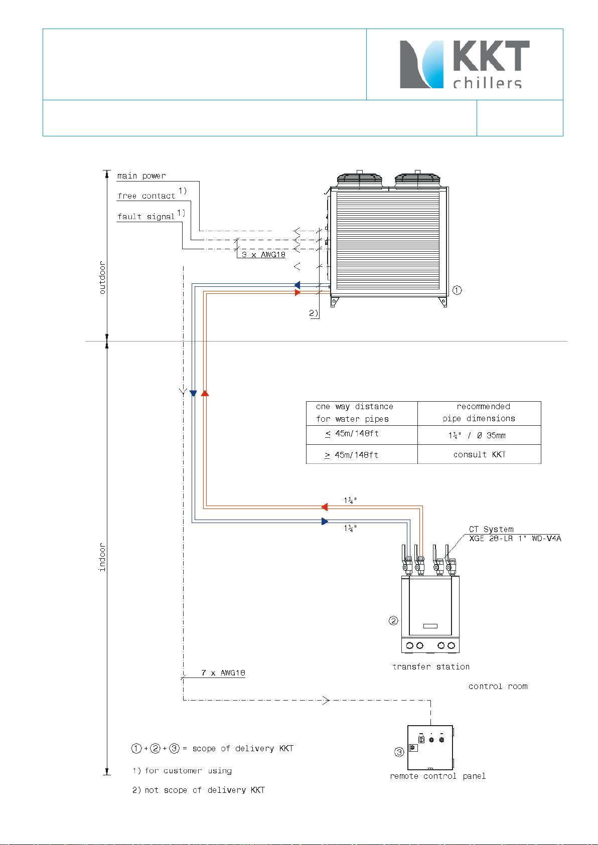
The industrial cooler of the KPC series consists of the refrigerant circuit, the cooling medium circulation, the transfer
station, the switch box and the remote control panel.
The refrigerant circuit includes compressor, primary side of the heat exchanger, air cooled condenser, necessary
equipment for liquid and gaseous refrigerant, safety and control device.
The cooling medium circulation includes secondary side of the heat exchanger with automatic air vent, medium heating
(electrical), circulation pump, expansion receiver, pressure relief valve, necessary equipment for cooling medium,
safety and control device.
The transfer station includes supply and return connections with shut-off valves, necessary equipment for cooling
medium, filling and draining cocks.
The refrigerant circuit and the cooling medium circulation are designed as a cooling block with built in switch box
The control elements are integrated in the front of the switch box. The remote control panel includes control switch,
lamp “run” as a status massage and lamp “fault” as a general fault massage.
The temperature set on the controller is kept automatically.
The cooling medium is constantly circulated by the pump.
The process heat is being transmitted from the cooling medium to the heat exchanger (evaporator of the refrigerant
circuit) and used for refrigerant evaporating (cooling). The compressor raises the gaseous refrigerant to a higher
pressure so that the warmth can be released via the condenser to the surrounding air. Consequently good air supply
and escape are vital for the proper running of the plant.
The cooling medium supply temperature can be changed from +7 °C to +12 °C by the temperature controller in front
of switch box.
Attention! Changes in the settings should only be made by qualified operatives.
The housing with stable welded, galvanized framework-construction, lateral cover-plates with drawer-edges made of
galvanized steel plate with ventilating nozzles worked into the top plate.
Framework-construction and top-plates are powder-coated on the inside and outside. All outer fastening screws rustproof, inspection-caps at the front easily removable for maintenance using casement-fastener caps.
Compressor, refrigerant and cooling medium mountings, additionally sound and rain-proofed using a galvanized coverplate.
Condenser axial-fans, pressure switch controlled condenser pressure dependent. Ventilators equipped with protectivegrating on the delivery side of the pump.
Laterally mounted condenser heat exchanger made of copper-aluminum with covering galvanized framework,
enameled fully in black.
\\FILER02\ALLGEMEIN\02 - TECHNISCHE UNTERLAGEN KKT\ORIGINALE\830XXX BEDIENUNGSANLEITUNGEN\KPC\83003702.K KPC108- L-US.DOC
Page 7

83003702.K Operating Instruction
Type KPC 108-L-U/S
page 7
Compressor-unit, consisting of:
Stable base-frame construction made of steel-profiles, powder-coated. Vibration-absorbing-mounted fully hermetic
SCROLL compressor with motor and suction-gas cooling. Complete special shut-off valves placed at the pressure and
suction side. Refrigerant power-inputs of flexible design. Refrigerant circuit with collector, filter-dryer, inspection glass
and moisture indicator, solenoid valve, service-valves as well as the complete internal copper-pipe work with refrigerant
and special oil filling.
Thermostatic expansion-valve and plumb high-capacity copper-brazed plate heat exchanger – evaporator. The plates
with optimized profile for efficiency heat transfer.
Evaporator and suction-side pipe work with diffusion-seal insulation.
Safety pack, consisting of:
Crankcase heater, high / low pressure switches as well as protective motor relay.
Shut-off ball valve at the cooling medium entry, dirt absorber, expansion tank, feeder and safety valves. High-pressure
centrifugal-pump adjusted to the overall system, filling and drainage valves with piping terminal, automatic air vent,
manometers and machine-thermometers in forward and return flow. Quantity balancing-valve, connection piece for
computer terminal in cooling medium supply.
Temperature control as hot gas by-pass control with solenoid valve.
Electronic digital temperature controller with control range limitation for set point and actually temperature.
Condenser fan control via pressure transmitter in refrigerant circuit and frequency inverter.
The high pressure pressostat (pressure switch) for system safety.
Internal cooling medium copper-brazed piping with diffusion-seal insulation.
All necessary block and clip angles used for refrigerant und cooling medium construction are made of rust-proof and
powder-coated material.
Switch-box with front door integrated in cooling block, system of protection IP 54, wired according to VDE-regulations
with a main switch, supply-check indicator lamp, phase monitoring relay and Siemens components such as, overload
release, sliding-panel, motor safety-switch, control-switch and indicator lamps.
A pump post-relay for the safety of the vaporizer as well as pot. proof contacts for "supply-control" and "collective fault
messages". It is still possible to connect a remote board.
The switch box of the outdoor version contains a switch box heater and a switch box ventilator.
\\FILER02\ALLGEMEIN\02 - TECHNISCHE UNTERLAGEN KKT\ORIGINALE\830XXX BEDIENUNGSANLEITUNGEN\KPC\83003702.K KPC108- L-US.DOC
Page 8
83003702.K Operating Instruction
Type KPC 108-L-U/S
page 8
Overview of outdoor industrial cooler KPC Series
\\FILER02\ALLGEMEIN\02 - TECHNISCHE UNTERLAGEN KKT\ORIGINALE\830XXX BEDIENUNGSANLEITUNGEN\KPC\83003702.K KPC108- L-US.DOC
Page 9

83003702.K Operating Instruction
Type KPC 108-L-U/S
page 9
KPC 108-L-U/S
\\FILER02\ALLGEMEIN\02 - TECHNISCHE UNTERLAGEN KKT\ORIGINALE\830XXX BEDIENUNGSANLEITUNGEN\KPC\83003702.K KPC108- L-US.DOC
Page 10

83003702.K Operating Instruction
Type KPC 108-L-U/S
page 10
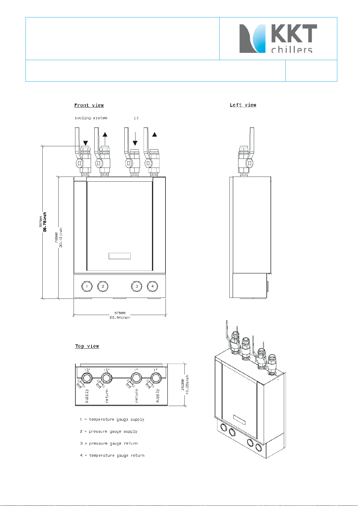
2.1 Drawings
2.1.1 KPC 108-L-U/S Outdoor Model
\\FILER02\ALLGEMEIN\02 - TECHNISCHE UNTERLAGEN KKT\ORIGINALE\830XXX BEDIENUNGSANLEITUNGEN\KPC\83003702.K KPC108- L-US.DOC
Page 11
83003702.K Operating Instruction
Type KPC 108-L-U/S
page 11
3 Brief operating instructions
3.1 Installing, maintenance and repair
Only qualified operatives with the requisite knowledge, equipment and facilities should maintenance and repair the
industrial cooler.
If its necessary to change the filling weight of the refrigerant circuit, please note:
Fill only with the refrigerants listed on the manufacturer name plate, and only up to the indicated filling weight.
OBSERVE THE SAFETY RULES
Before work on the industrial cooler, switch the plant to voltage-free and make sure against unauthorized switching
ON.
3.2 Linking to power supply
The size of the connection cable had to be conform to the local regulations. For current values and power input see
Switch Gear.
The industrial coolers of the KPC series are generally designed for a main supply of 480V 3Ph 60 Hz.
The connection L1, L2, L3, PE is performed via the terminal block in the switch box.
The cooling block is switched on via the master switch .
3.3 Filling the unit with cooling medium
The cooling circulation will be filled with cooling medium (mixture of 62 % clean water – drinking water quality – and
38 % glycol).
Open front panel and fill to a pressure of 1,5 bar via the feed cock.
After filling, check all connections for leakage.
3.4 EMC Compatibility and Grounding
This comments are compiled to help the field electrician to install the grounding of the power supply and to get a EMC
Compatibility.
All electrical equipment produces radio and line-borne interference at various frequencies. The cables pass this on to
the environment like an aerial.
The basic countermeasures are isolation of the wiring of control and power components, proper grounding and
shielding of cables.
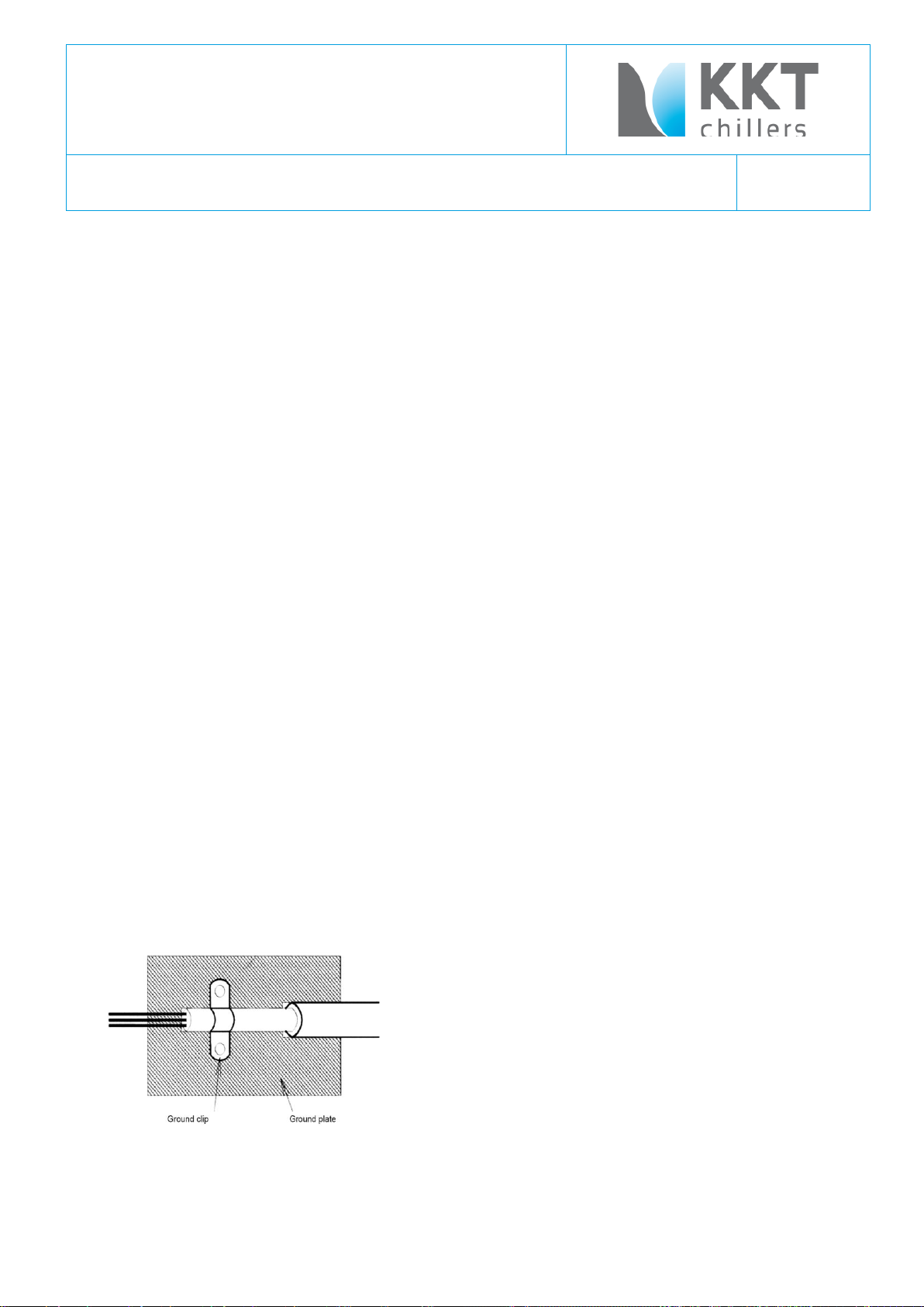
A large contact area is necessary for low-impedance grounding of HF interference. The use of grounding straps
instead of cables is therefore definitely advisable.
Moreover, cable shields must be
connected with purpose-made ground
clips.
The grounding surface must be highly
conductive bare metal. Remove any
coats of varnish and paint.
The width of the grounding wire must be min. 16mm² (AWG 6) or of the same width of the power supply.
The grounding must be an isolated ground and must connected on the ground terminal (X1) in the switch cabinet.
The ground resistance must be less than 10 Ohm.
\\FILER02\ALLGEMEIN\02 - TECHNISCHE UNTERLAGEN KKT\ORIGINALE\830XXX BEDIENUNGSANLEITUNGEN\KPC\83003702.K KPC108- L-US.DOC
Page 12

83003702.K Operating Instruction
Type KPC 108-L-U/S
page 12
Metal cable conduits are not allowed for grounding.
The piping of the chiller (supply and return) have to be grounded too.
Do not share the ground wire with other devices.
Always use a ground wire that complies with technical standards on electrical equipment and minimize the length of
the ground wire.
\\FILER02\ALLGEMEIN\02 - TECHNISCHE UNTERLAGEN KKT\ORIGINALE\830XXX BEDIENUNGSANLEITUNGEN\KPC\83003702.K KPC108- L-US.DOC
Page 13
83003702.K Operating Instruction
Type KPC 108-L-U/S
page 13
remote control panel
main switch
control switch
"0"
"1"
"0"
"1"
"0"
"Auto"
"Hand"
standard
operation: pump
runs, compressor
and condenser fan
are running on
demand (water
temp. higher than
8°C), water heater
works on demand
(water temp. below
4°C),
overheating
protection: pump
switches of if water
temp. Is longer
than 30 minutes
higher than 30°C)
X X X
X
(or no
remote
control
connected
with chiller)
X
X
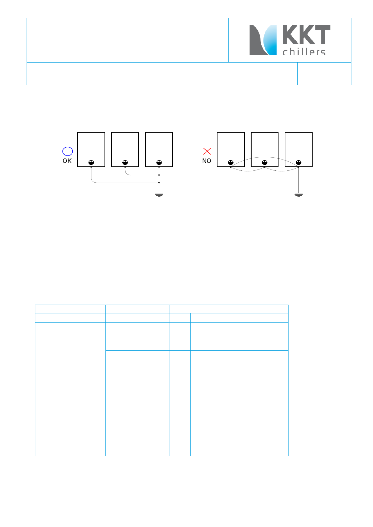
When using more than one Inverter, be careful not to loop the ground wire.
(e.g. a CT-Chiller KPC108-L-U/S stands near an Avanto-Chiller KCC215-L-U/S)
3.5 Draining air from the unit
The KPC 108 includes a cooling medium circulation.
In case air gets out of the system the cooling medium pressure drops down. If that happens you have to check the
cooling medium pressure and if its to low you have to refill the cooling medium circulation as shown in 3.3
The procedure should be repeated until no more air is in the cooling medium circulation.
After all these steps, turn both switches to position "1". If all the prerequisites for operation have been met, the
industrial cooler will start after 1 minute.
In case of malfunction: search for faults taken note of TROUBLE SHOOTING in this manual.
3.6 Switch settings of main chiller functions (exfactory settings)
\\FILER02\ALLGEMEIN\02 - TECHNISCHE UNTERLAGEN KKT\ORIGINALE\830XXX BEDIENUNGSANLEITUNGEN\KPC\83003702.K KPC108- L-US.DOC
Page 14

83003702.K Operating Instruction
Type KPC 108-L-U/S
page 14
stand by mode:
refrigerant circuit is
"switched off",
pump and heater
are running on
demand (water
temp. below 4°C),
X
(or no
remote
control
connected
with chiller)
X X
X X X
X
X
switched off:
no function (switch
cabinet is not
under voltage)
position without effect
X position without effect
remark: with the position "Auto" on the control switch is the remote control panel active.
\\FILER02\ALLGEMEIN\02 - TECHNISCHE UNTERLAGEN KKT\ORIGINALE\830XXX BEDIENUNGSANLEITUNGEN\KPC\83003702.K KPC108- L-US.DOC
Page 15

83003702.K Operating Instruction
Type KPC 108-L-U/S
page 15
4 Technical Specifications
4.1 Data sheet
Outdoor
Dimensions Depth 962 mm
Breadth 1,410 mm
Height 1,620 mm
Weight without refrigerant load 540 kg
Weight with refrigerant load 7.0 kg
Number of fans 2
Quantity of air 18,000
Refrigerant R134a
Required quantity of refrigerant 7 kg
Low-pressure switch see testreport
High-pressure switch 19 bar
Water connection inlet 1 1/4“ inside
Water connection outlet 1 1/4“ inside
Cold water temperature outlet min. 7 °C +/-0,5 K
Cold water temperature outlet max. 12 °C
Primary water pump type CR3-6
Rated water capacity max. 4.1 m³/h
Rated water pressure 3.0 bar
Ambient temperature min. -20 °C
max. +48 °C
Cooling capacity 15,0 kW
Rated cold water outlet temperature 11 °C
temperature of surroundings 40 °C
Exactitude of temperature ±0.5 K
Main supply 480 V/3Ph/60 Hz
Control voltage 24 V
Fluctuations in main voltage max. ±5 %
Fluctuations in output max. ±5 %
Power input max. 9 kW
Noise level at 5m 65 db(A) -
\\FILER02\ALLGEMEIN\02 - TECHNISCHE UNTERLAGEN KKT\ORIGINALE\830XXX BEDIENUNGSANLEITUNGEN\KPC\83003702.K KPC108- L-US.DOC
Page 16

83003702.K Operating Instruction
Type KPC 108-L-U/S
page 16
5 Transport
Transport on company premises may be done with a forklift truck. The appliance must however be kept in an upright
position and on no account tipped to the side. A visual inspection should be made on delivery to check for any damage.
Complaints should be made immediately to the haulage contractor and the insurance company must be notified at
once.
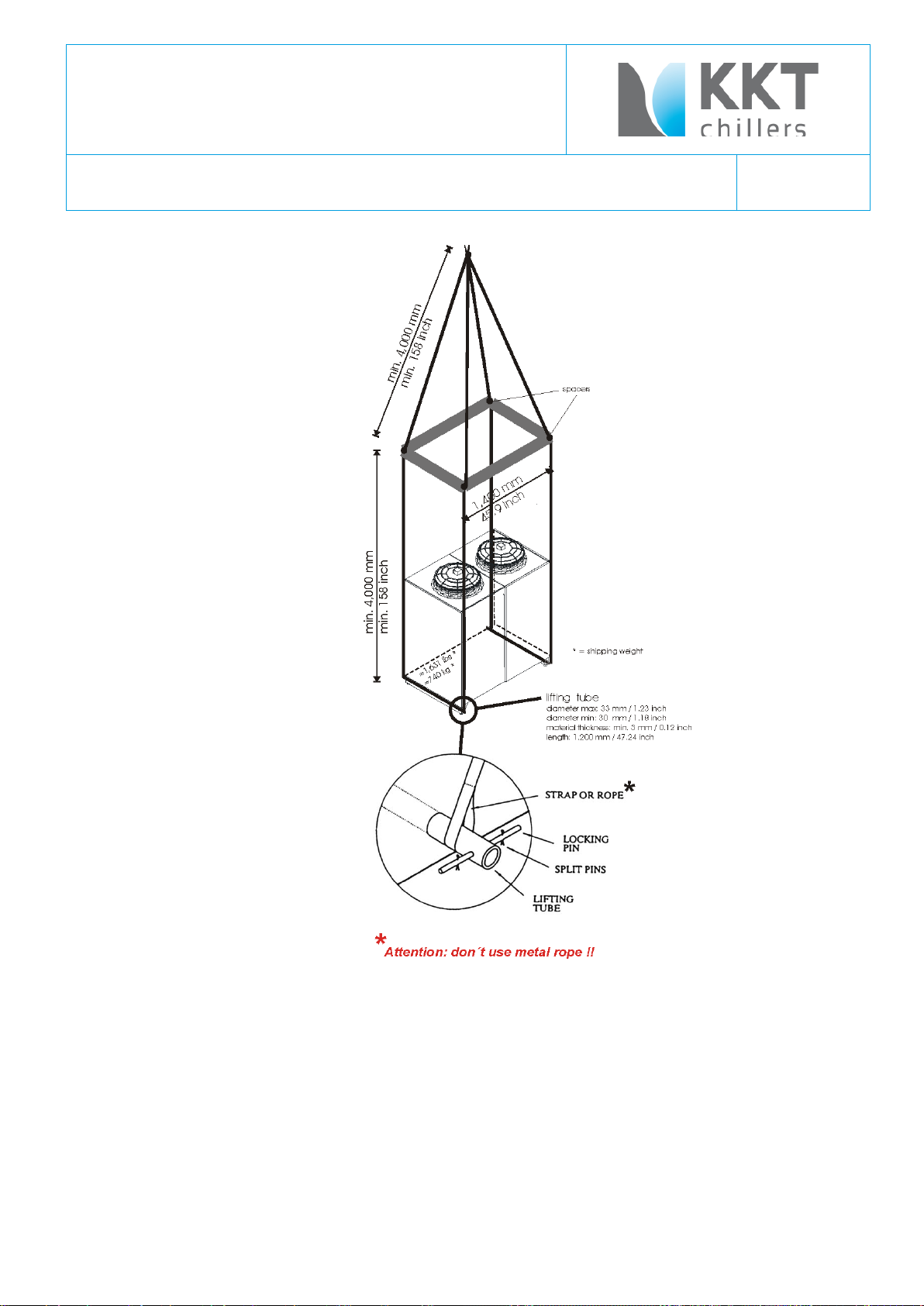
When transporting by crane,
please ensure that the housing is not subjected to pressure at the sides.
Place the lifting tubes in the holes in the feet at the base of the chiller. Lock the ends of the tubes in position with
locking pins and split pins as shown.
The capacity of the lifting gear must be adequate to lift the load in question. Check the weight of the unit, the capacity
of the lifting gear and ropes and there condition.
Check the suitability of the aforementioned equipment.
\\FILER02\ALLGEMEIN\02 - TECHNISCHE UNTERLAGEN KKT\ORIGINALE\830XXX BEDIENUNGSANLEITUNGEN\KPC\83003702.K KPC108- L-US.DOC
Page 17
83003702.K Operating Instruction
Type KPC 108-L-U/S
page 17
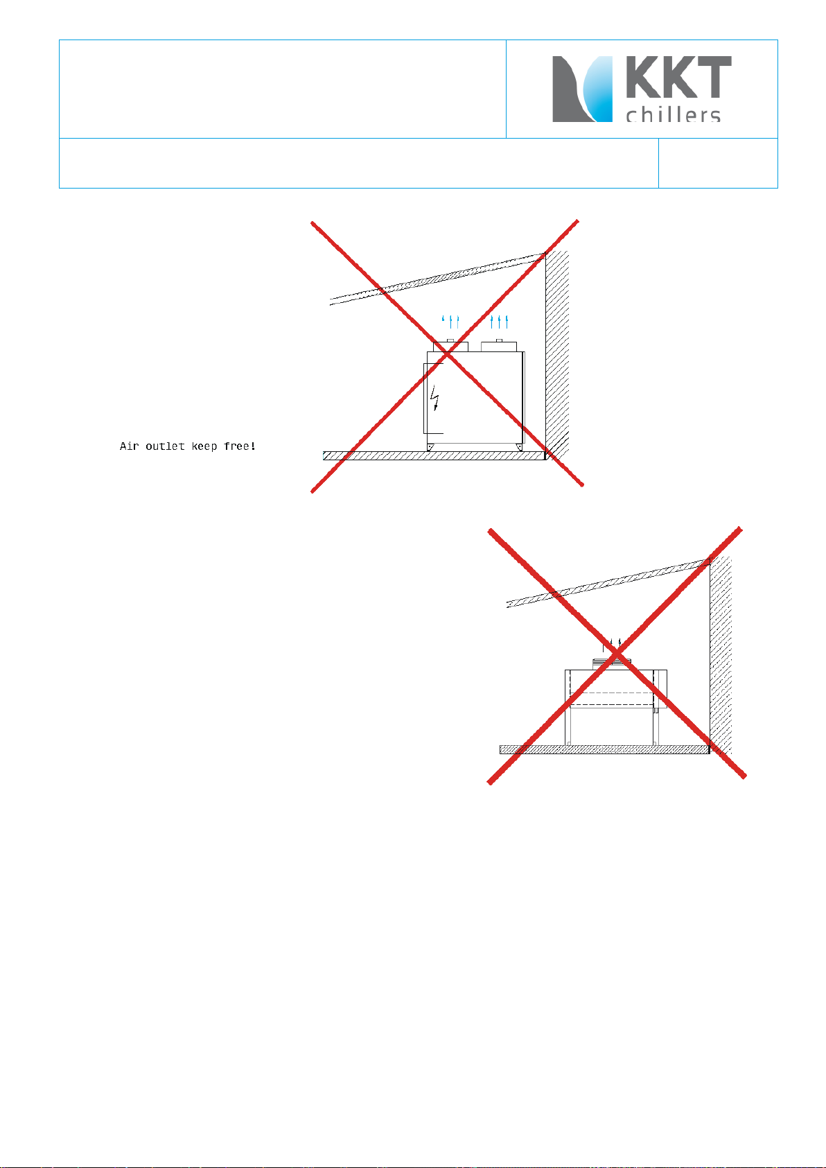
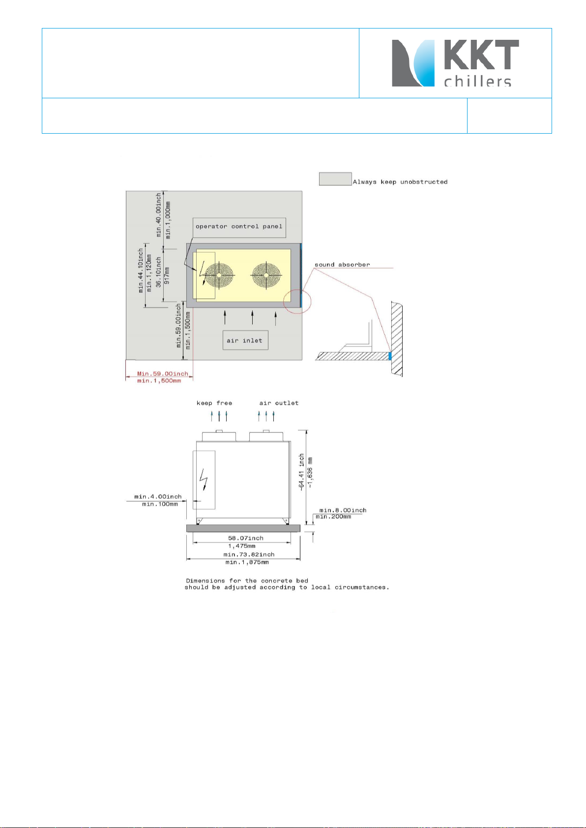
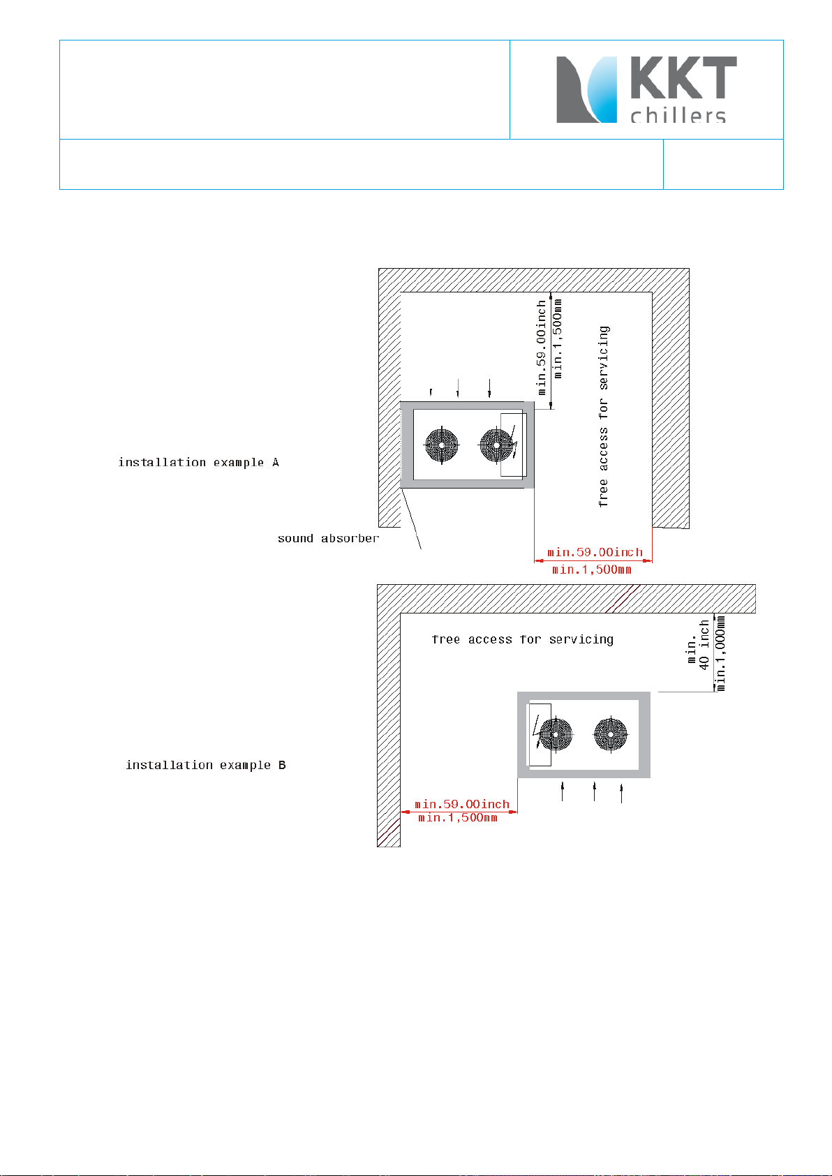
6 Installing the industrial cooler
The plant should be mounted in an upright position on a stable foundation.
(Weight with load: see technical specifications).
A distance of approx. 1 m should be kept free on all sides to allow sufficient access for operation and maintenance.
A space of 1,5 m must be left above the apparatus to ensure that air exhaust can leave freely by the outdoor model.
Further details can be found in the following installation plans.
\\FILER02\ALLGEMEIN\02 - TECHNISCHE UNTERLAGEN KKT\ORIGINALE\830XXX BEDIENUNGSANLEITUNGEN\KPC\83003702.K KPC108- L-US.DOC
Page 18
83003702.K Operating Instruction
Type KPC 108-L-U/S
page 18
Type KPC 108-L-U/S Outdoor Unit
A distance of approx. 1 m should be kept free on all sides to allow sufficient access for operation and maintenance.
Picture is only to explain and not guilty for measurement.
\\FILER02\ALLGEMEIN\02 - TECHNISCHE UNTERLAGEN KKT\ORIGINALE\830XXX BEDIENUNGSANLEITUNGEN\KPC\83003702.K KPC108- L-US.DOC
Page 19
83003702.K Operating Instruction
Type KPC 108-L-U/S
page 19
\\FILER02\ALLGEMEIN\02 - TECHNISCHE UNTERLAGEN KKT\ORIGINALE\830XXX BEDIENUNGSANLEITUNGEN\KPC\83003702.K KPC108- L-US.DOC
Page 20
83003702.K Operating Instruction
Type KPC 108-L-U/S
page 20
\\FILER02\ALLGEMEIN\02 - TECHNISCHE UNTERLAGEN KKT\ORIGINALE\830XXX BEDIENUNGSANLEITUNGEN\KPC\83003702.K KPC108- L-US.DOC
Page 21
83003702.K Operating Instruction
Type KPC 108-L-U/S
page 21
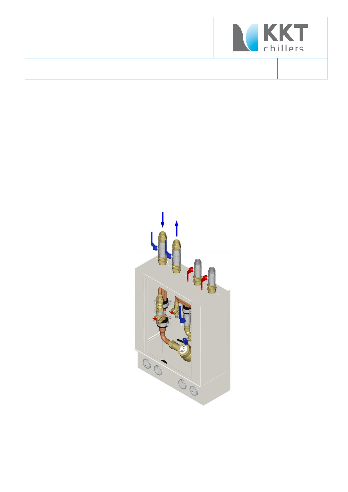
7 Notes on the cooling medium connections
The cooling medium connections between industrial cooler of the KPC series and the transfer station can be made of
steel, copper or plastic. The nominal widths of the piping for distances of up to approx. 45 m should match at least the
dimensions of the fittings on the appliance (see technical specifications).
The proper way to seal the European fittings can be done with any of following steps.
Pipe sealing cord. There are a number of brands available, however we use Loctite 55
Teflon Tape and a Anaerobic sealant.
Teflon Tape an Nylog sealant.
As with any sealant, the application instruction must be followed for proper use.
Reductions in diameter should be avoided. In case of longer pipelines, the pump pressure should be tested. When
choosing the pipe materials, ensure that no electrochemical series are created.
Transfer station
\\FILER02\ALLGEMEIN\02 - TECHNISCHE UNTERLAGEN KKT\ORIGINALE\830XXX BEDIENUNGSANLEITUNGEN\KPC\83003702.K KPC108- L-US.DOC
Page 22
83003702.K Operating Instruction
Type KPC 108-L-U/S
page 22
\\FILER02\ALLGEMEIN\02 - TECHNISCHE UNTERLAGEN KKT\ORIGINALE\830XXX BEDIENUNGSANLEITUNGEN\KPC\83003702.K KPC108- L-US.DOC
Page 23
83003702.K Operating Instruction
Type KPC 108-L-U/S
page 23
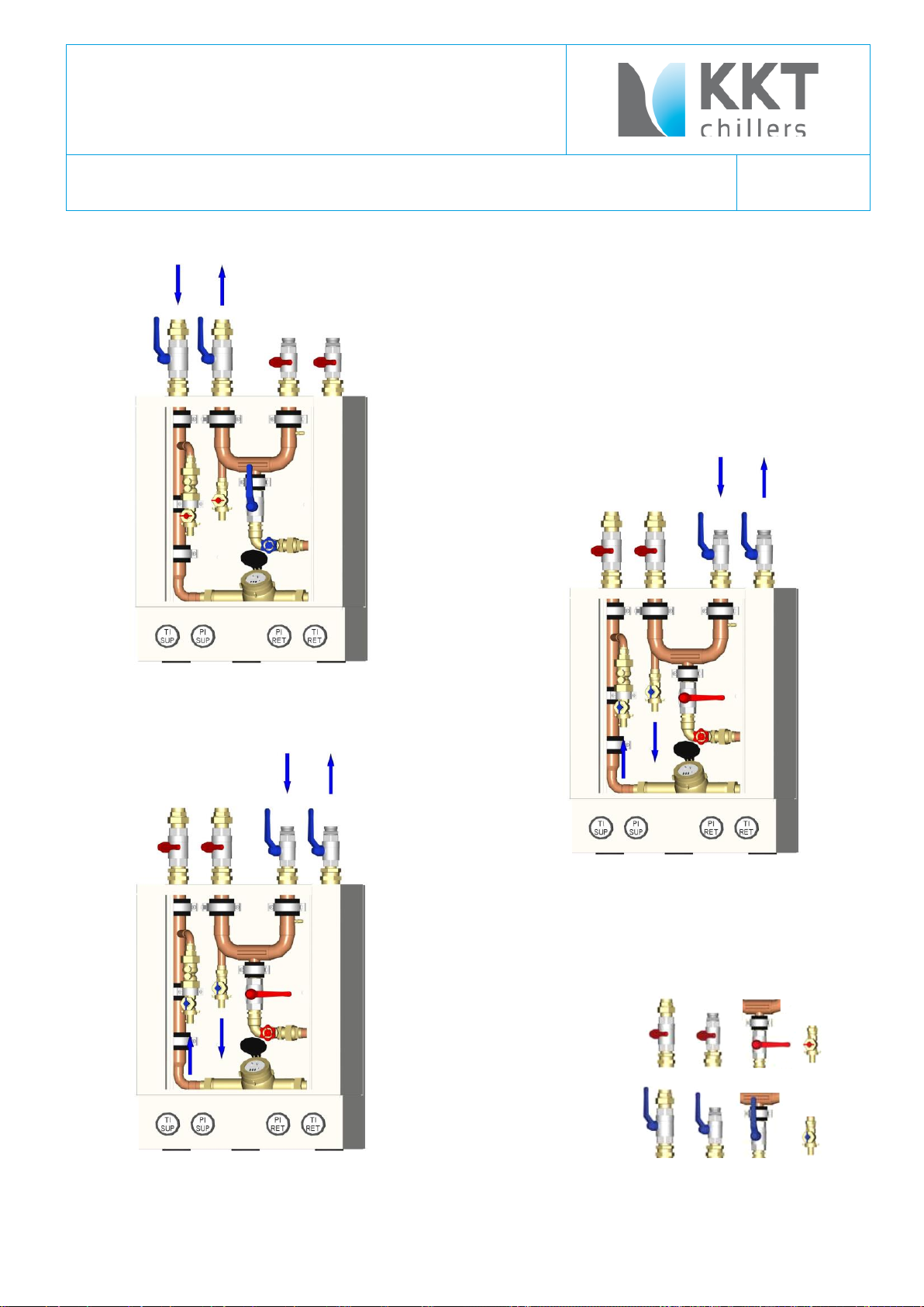
1.) regulation phase
2.) in operation
3. ) emergency cooling
Closed:
Open:
\\FILER02\ALLGEMEIN\02 - TECHNISCHE UNTERLAGEN KKT\ORIGINALE\830XXX BEDIENUNGSANLEITUNGEN\KPC\83003702.K KPC108- L-US.DOC
Page 24

83003702.K Operating Instruction
Type KPC 108-L-U/S
page 24
8 Power supply
The power supply is wired to the terminal block in the junction box of the transformer (see technical specifications).
The layout of the main cable must comply with the current values and the regulations of the local electricity company.
The Type KPC 108 L-U/S (Outdoor-Version) must be run with fuses of no less than 35 A in size ( see nameplate).
The supply voltage must be 480V / 3ph / 60 Hz.
The master and control switches must be in the "OFF" position when the plant is connected.
The supply line is attached to the terminal PE, L1 L2, L3,
\\FILER02\ALLGEMEIN\02 - TECHNISCHE UNTERLAGEN KKT\ORIGINALE\830XXX BEDIENUNGSANLEITUNGEN\KPC\83003702.K KPC108- L-US.DOC
Page 25

83003702.K Operating Instruction
Type KPC 108-L-U/S
page 25
9 Operating instructions
9.1 Switching ON the Industrial Cooler
The cooling medium circulation must be completely filled and all air must be removed.
Turn the “main switch” switch “ON” - to the position “1”
(For additional information about the switch settings please see chapter 3.8 “Swithch settings of main chiller functions
(exfactory settings).
Turn the control switch “ON” this means to “Automatik” if the remote control panel is installed otherwise to position
“HAND”.
The cold water pump starts.
The flow switch protection cuts off the compressor during start-up, if the water circuit has not enough water pressure.
The pressure on the pump supply side rises directly with the system pressure. If not: – the plant has either a leak or
insufficient cooling medium.
A flow switch acts to prevent freezing of the evaporator if and when water volumes drop.
The compressor switches on when the water becomes to warm.
The refrigeration compressor keeps running as long as cooling is required and the reference value for the water
temperature has not been reached. The fine adjustment is performed by hot gas by-pass solenoid valve.
The cooling medium pump remains in constant operation.
The compressor is switched off during circulation in cases of low or high pressure in the refrigerant circuit (fault
massage), or when the cooling is not required (normal).
When switched off in the normal way, the overload protection provides the compressor restart switching lag.
9.2 High/low pressure control
The high-pressure pressostat reacts by shutting off the compressor, when the refrigerant pressure after compressor is
higher then 19 bar.
Cause of this include - failure of condenser fans,
- high outdoor temperatures,
- a dirty condenser heat exchanger.
The compressor can only be put back in operation when the pressure has dropped and the reset switch on the high
pressure pressostat is activated.
An automatic start has not been provided for you have to do a reset on the high – pressure pressostat.
The low-pressure pressostat reacts by shutting off the compressor, when the refrigerant pressure before compressor
sinks to the magnitude mentioned in test report (Settings, Low-pressure-switch, different).
When the pressure rises to high enough, the compressor will switch on again automatically.
The start-up switching lag amount to the adjusted value in the testreport.
\\FILER02\ALLGEMEIN\02 - TECHNISCHE UNTERLAGEN KKT\ORIGINALE\830XXX BEDIENUNGSANLEITUNGEN\KPC\83003702.K KPC108- L-US.DOC
Page 26

83003702.K Operating Instruction
Type KPC 108-L-U/S
page 26
9.3 Electronic controls
The control system consists of a 2-step controller. The reference value is set value see testreport for the outlet
temperature. The sensor for the controller is installed on the outlet side.
9.4 Regulating refrigerating capacity
The exact regulation of the leaving temperature is achieved by means of 2-step controllers and hot gas by-pass
injectors with solenoid valves. The setting is based on approx. 50% of each machine’s refrigerating capacity.
9.5 Condenser pressure regulation
the condenser-pressure is regulated with help of the Frequency Inverter.
– see caption “Frequency Inverter”
9.6 Safety functions to protect components of cooling water circuit
When the refrigerant cycle is failure the water pump heats up the cooling medium.
To prevent the components in the cooling circuit, there is a safety function which switches off the pump if the water
temperature is longer than 30 minutes over 30 °C.
When this function has worked, the lamp (7H3 – in switch gear) on the switch box lights and the water pump has
stopped.
The lamp is labelled “reset overheating water”.
When the problem in the refrigerant circuit is solved, you have to pull down the button “reset overheating water”. This
is the requirement that the pump can run again.
9.7 Collective alarm
The red warning lamp in the door of the switch box lights up when one of the safety sensors has been triggered. The
cause of the error can be identified more exactly by means of the LEDs in the switch box. For the purpose of external
evaluation of the error signal, the collective alarm message can be accessed, potential-free, from the terminal. (See
also circuit diagram)
9.8 Flow switch
Monitors the water flow volume through the evaporator and shuts the device down completely if the min. water
quantity is reached.
9.9 Dirt trap
The dirt trap is fully installed (see Shema in the appendix) and protects the evaporator from dirt.
As a matter of principle the plant is to be operated with clean water. With that regular servicing of the filter is
unnecessary.
Caution! Work on electric and refrigerant circuits should only be performed by qualified operatives.
Observe the safety rules!
\\FILER02\ALLGEMEIN\02 - TECHNISCHE UNTERLAGEN KKT\ORIGINALE\830XXX BEDIENUNGSANLEITUNGEN\KPC\83003702.K KPC108- L-US.DOC
Page 27

83003702.K Operating Instruction
Type KPC 108-L-U/S
page 27
10 Preventiv Maintenance
Caution! Work on electric and refrigerant circuits should only be performed by qualified operatives.
Observe the safety rules!
Service and maintenance should always be carried out by skilled technician and, where possible, under a maintenance
contract. Nevertheless, certain routine work can be effectively carried out by non-specialists and may become
important factor in preventing future damage to the plant.
Weekly Check
1. Check the working of the compressor:
Look out for too high head temperatures or suspicious noises.
2. Check the R134a through the sight-glass
3. Check that fans are rotating normally and not making unusual noises
4. Check that the temperatures is within the accepted limit.
If it is not, check that all the separate elements of the unit are working, by switching them on individually.
If they are not, see the “ Trouble shooting”
Two –monthly Check
a. The air conditioner unit:
1. Check the air filter and replace it if necessary
2. Check the air circulation fans and check that the bearings are not heating up
3. Check that the heating elements work, by switching them to “MAN”
4. Switch cooling system to “MAN” and check that it is in full working order
5. Check the compressor temperature.
6. Check there is no ice accumulations on the evaporator.
7. Check that the warning lights on the display panel are working properly.
8. Check the main voltage between all the phases
9. Check the principal and secondary circuits thoroughly, inspect the overload cut-outs and thermal
relays.
10. Pull out the fuses to check that the safety system works.
\\FILER02\ALLGEMEIN\02 - TECHNISCHE UNTERLAGEN KKT\ORIGINALE\830XXX BEDIENUNGSANLEITUNGEN\KPC\83003702.K KPC108- L-US.DOC
Page 28

83003702.K Operating Instruction
Type KPC 108-L-U/S
page 28
b. The condenser
1. Air cooled units:
Make sure that the fan motor and the condensing coil are working efficiently, if necessary clean the
coil.
c. Electric heater
1. Check the heater coil
2. Check the overheating protection switch in the head of the heater
3. Check the fuses
\\FILER02\ALLGEMEIN\02 - TECHNISCHE UNTERLAGEN KKT\ORIGINALE\830XXX BEDIENUNGSANLEITUNGEN\KPC\83003702.K KPC108- L-US.DOC
Page 29

83003702.K Operating Instruction
Type KPC 108-L-U/S
page 29
KIND OF TROUBLE
CAUSE
ELIMINATION
malfunction of
plant/system
1. power failure
2. feeler of temperatur controller
defective
3. feeler malfunction
- check mains connection
- check feeler:
clamp feeler and measure the resistance
- check thermostat:
bridge controller the thermostat relay
should shut and the compressor should
start
- check feeler:
clamp feeler and measure the resistance
- replace feeler ( sensor ) is defect.
malfunction of pump
1. main switch not switched on
2. control switch on 'OFF'
3. main fuse defective
4. fuse for control current defective
5. pump motor defective
6. flow controller responded
7. shortage of water
8. lamp “overheating water reset” lights
- switch on main switch
- switch control switch to 'AUTO'
- replace fuse
- replace fuse
- replace motor
- check water quantity
- check system pressure, clean strainer
- check the refrigerant circuit – see capture
“Water pump”
still malfunction of
pump
1. overload trip of pump protection
interrupted control circuit
- main switch to '0', push in overload trip
pump makes
gurgling noise
1. circuit is not completely vented
- vent and fill up with water
compressor stops
1. Klixon tripped
2. Klixon defective
- wait until compressor cooled down;
perhaps clean condenser or provide fresh
air supply
- replace Klixon
malfunction of
refrigerating machine
1. control thermostat stopped machine,
return temperature too cold
- to check function, level down adjustments,
wait until return temperature rised
11 TROUBLE SHOOTING
\\FILER02\ALLGEMEIN\02 - TECHNISCHE UNTERLAGEN KKT\ORIGINALE\830XXX BEDIENUNGSANLEITUNGEN\KPC\83003702.K KPC108- L-US.DOC
Page 30

83003702.K Operating Instruction
Type KPC 108-L-U/S
page 30
KIND OF TROUBLE
CAUSE
ELIMINATION
still malfunction of
refrigerating machine
1. low pressure in refrigerant circuit
- plant looses refrigerant
- dryer in liquid pipe dirty
- pressure relief valve defective
- solenoid valve in liquid pipe defective
2. high pressure in refrigerant circuit
- condenser dirty
- fan defective
- outside temperature too high
- condenser control pressostate
defective
- find leak, seal, refill circuit
- replace dryer
- replace pressure relief valve
- replace solenoid valve
- clean condenser
- put right electric cause;
check fuses
- spray condenser with water
- replace pressostate
refrigerating machine
starts and stops
short-termed
1. not enough fresh air supply for
condenser;
high pressure pressostate tries to
protect refrigerating machine against
overload
2. not enough pressure of refrigerant
circuit;
refrigerant partly escaped; diminished
pressure switch shut down compressor
- provide enough fresh air supply and fresh
air removal;
get rid of short-circuit across fresh air and
exhaust air
- find leak, seal, refill circuit
not enough
refrigeration power
1. air in water circuit
2. fallen below minimum water agitation
quantity
3. not enough fresh air supply for
condenser
4. not enough refrigerant in circuit
- vent system
- design cross-section of water pipe right;
perhaps open check valve in water circuit
completely, increase pipe cross-section
- provide enough fresh air supply and fresh
air removal;
get rid of short-circuit across fresh air and
exhaust air
- find leak, seal, refill circuit
electrical heater in
water circuit does
not work
1. the electrical heating box becomes
more than 266°F (130°C)
=> the safety temperature limiter
breaks the contact
2. control the pressure from the water
circuit
3. control the Parameter of the
temperature controller witch switches
the heater.
- the reset (is under the cover of the heater)
must be reset manually
- if necessary: prepare the cause of water
lack and fill the water circuit
- if necessary: set the right Parameter in the
temperature controller (which switches the
electrical heater)
\\FILER02\ALLGEMEIN\02 - TECHNISCHE UNTERLAGEN KKT\ORIGINALE\830XXX BEDIENUNGSANLEITUNGEN\KPC\83003702.K KPC108- L-US.DOC
Page 31

83003702.K Operating Instruction
Type KPC 108-L-U/S
page 31
Single-Stage Hermetic Compliant SCROLL Motor-Compressor
12 Description of the individual parts
12.1 Compressor
\\FILER02\ALLGEMEIN\02 - TECHNISCHE UNTERLAGEN KKT\ORIGINALE\830XXX BEDIENUNGSANLEITUNGEN\KPC\83003702.K KPC108- L-US.DOC
Page 32

83003702.K Operating Instruction
Type KPC 108-L-U/S
page 32
Single-Stage Hermetic Compliant SCROLL Motor-Compressor
\\FILER02\ALLGEMEIN\02 - TECHNISCHE UNTERLAGEN KKT\ORIGINALE\830XXX BEDIENUNGSANLEITUNGEN\KPC\83003702.K KPC108- L-US.DOC
Page 33

83003702.K Operating Instruction
Type KPC 108-L-U/S
page 33
Single-Stage Hermetic Compliant SCROLL Motor-Compressor
Type ZR xx K3E-TWD-561
Technical Data
Accessories
Crankcase Heater: 220 – 240 V 50 – 60 Hz
\\FILER02\ALLGEMEIN\02 - TECHNISCHE UNTERLAGEN KKT\ORIGINALE\830XXX BEDIENUNGSANLEITUNGEN\KPC\83003702.K KPC108- L-US.DOC
Page 34

83003702.K Operating Instruction
Type KPC 108-L-U/S
page 34
Single-Stage Hermetic Compliant SCROLL Motor-Compressor
Type ZR xx K3E-TWD-561
Z R 90K 3 E - TWD
-
561
1 2 3 4 5 6 7
7,2 °C
evaporating temperature
8,3 K
liquid sub cooling
54,4 °C
condensing temperature
35 °C
ambient temperature
11 K
suction gas superheat
Introduction
Scroll Compres sors in the ra nge fro m ZR 90 K3 * to ZR 38 0 KC* are characterized by the pilot duty motor
protection system that uses internal sensors and an external electronic module to protect the compressor
against motor overheating and excessive discharge temperature. For additional information, please refer to the
Copeland website at www.ecopeland.com.
Safety Instructions
Only qualified personnel should install and repair COPELAND compressors.
• Refrigerant compressors must be employed only for the use they are made for.
• Only approved refrigerant and refrigerating oils must be used.
• Do not start the compressor until it is charged with refrigerant.
• Correctly used, the compressor and the pressure line piping may reach temperatures that may cause burning if
touched.
• Wear safety goggles when working on open systems.
• If the refrigerant needs to be removed from the system, do not disperse it in the environment, use the correct
equipment & method of removal.
• Trained electrical personnel must connect the compressor and its accessories.
• All valid standards for connecting electrical and refrigeration equipment must be observed.
• Limit values for the supply voltage of the unit may not be exceeded.
• It is not allowed to run a test without the compressor being connected to the s ystem and without refrigerant.
It is of vital importance that the discharge stop valve has been fully opened before the compressor is
started. If the discharge stop valve is closed or partly closed an unacceptable pressure with accordingly high
temperatures may develop in the cylinder head. When operating with air the so called diesel effect may occur,
i.e. the air sucked in is mixed with oil gas and can explode due to the high temperature in the cylinder head, and
thereby destroy the compressor.
Model Designation
1 - compressor family: Z = Scroll
2 - application range: R = high/medium temperature
3 - nominal capacity [BTU/h] @ 60 Hz and ARI conditions (*see below) using multipliers "K" for 1000 and
4 - model variation
5 - oil type: E = POE oil
6 - motor version: TWD (400V/460V/3/50/60 Hz)
7 - bill of material number: 561: Rotalock connection, 24 V AC module (ZR90K3* to ZR19M3*)
*ARI-Conditions:
\\FILER02\ALLGEMEIN\02 - TECHNISCHE UNTERLAGEN KKT\ORIGINALE\830XXX BEDIENUNGSANLEITUNGEN\KPC\83003702.K KPC108- L-US.DOC
"M" for 10 000
Page 35

83003702.K Operating Instruction
Type KPC 108-L-U/S
page 35
Qualified Refrigerant
R134a has been qualified for the models ZR 90 K3E…ZR 380 KCE.
Lubrication and Oil Removal
The compressor is supplied with an initial oil charge. The standard oil charge for use with refrigerants R134a is a
polyolester (POE) lubricant Copeland 3MAF (32 cSt). In the field the oil level could be topped up with ICI Emkarate RL
32 CF or Mobil EAL Arctic 22 CC, if 3MAF is not available.
\\FILER02\ALLGEMEIN\02 - TECHNISCHE UNTERLAGEN KKT\ORIGINALE\830XXX BEDIENUNGSANLEITUNGEN\KPC\83003702.K KPC108- L-US.DOC
Page 36

83003702.K Operating Instruction
Type KPC 108-L-U/S
page 36
Single-Stage Hermetic Compliant SCROLL Motor-Compressor
Type ZR xx K3E-TWD-561
The crankcase heater must be mounted below the oil removal valve located on the
bottom shell.
The crankcase heater must remain energized during compressor off cycles.
The crankcase heater must be turned on a minimum of 12 hours prior to starting
the compressor. This will prevent oil dilution and bearing stress on initial start up.
If it is not feasible to turn on the crankcase heater 12 hours in advance of starting
the compressor, then use one of the techniques listed below to prevent possible
flooded-start damage to the compressor:
If oil is charged into a system it is recommended to charge systems with POE containing no more than 50 ppm moisture
content. If the moisture content of the oil in a refrigeration system reaches unacceptable high levels, corrosion and copper
plating may occur. The system should be evacuated down to 0.3 mbar or lower. If there is uncertainty, as to the moisture
content in the system, an oil sample should be taken and tested for moisture. Sight glass/moisture indicator will just
show the moisture contents of the refrigerant. The actual moisture level of POE would be higher than the sight glass
specifies. This is a result of the high hygroscopicity of the POE oil. Oil samples would have to be taken from the system
and analyzed to determine the actual moisture content of the lubricant.
Crankcase Heater (240 V, 70 W)
1) Direct a 500 watt heat lamp or other safe heat source (do not use torch) at the lower shell of the compressor for
approximately 30 minutes to boil off any liquid refrigerant prior to starting; or
2) Bump start the compressor by manually energizing the compressor contactor for about one second. Wait five
seconds and again manually energize compressor for one second. Repeat this cycle several times until the liquid in
the shell has been boiled off and the compressor can be safely started and run continuously.
Discharge Temperature Protection
A thermistor with a nominal response temperature of 140 °C is located in the discharge port of the fixed scroll. Excessive discharge
temperature will cause the electronic protector module to trip. The discharge gas sensor is wired in series with the motor
thermistor chain.
\\FILER02\ALLGEMEIN\02 - TECHNISCHE UNTERLAGEN KKT\ORIGINALE\830XXX BEDIENUNGSANLEITUNGEN\KPC\83003702.K KPC108- L-US.DOC
Page 37

83003702.K Operating Instruction
Type KPC 108-L-U/S
page 37
Single-Stage Hermetic Compliant SCROLL Motor-Compressor
Type ZR xx K3E-TWD-561
Electronic Motor Protection
The electronic motor protection system as used in all ZR 90 K3* ... ZR 380 KC* models is identified by a “W” as the
center letter in the motor code. This system utilizes the temperature dependent resistance of thermistors (also called
PTC resistances) to read the winding temperature. A chain of four thermistors connected in series is embedded in the
motor windings so that the temperature of the thermistors can follow the winding temperature with little inertia. An
electronic module is required to process the resistance values and trip a control relay depending on the thermistor
resistance. The resistance curve can be designed for different operating points, the nominal response
temperature (NAT), e.g. 80 °C, 130 °C, 140 °C and must comply with the tolerances laid out in the standard DIN 44081.
\\FILER02\ALLGEMEIN\02 - TECHNISCHE UNTERLAGEN KKT\ORIGINALE\830XXX BEDIENUNGSANLEITUNGEN\KPC\83003702.K KPC108- L-US.DOC
Page 38

83003702.K Operating Instruction
Type KPC 108-L-U/S
page 38
Single-Stage Hermetic Compliant SCROLL Motor-Compressor
Type ZR xx K3E-TWD-561
Module
For protection in case of blocked rotor one thermistor for each phase is embedded in the winding heads on the upper
(suction gas) side of the compressor motor (NAT 100 °C). A fourth thermistor is located in a winding head at the lower end
of the motor (NAT 140 °C). A fifth sensor is located in the discharge port of the fixed scroll to control discharge gas
superheat (NAT 140 °C). The entire chain is internally led to the fusite from where it is connected to the module connections S1
and S2. When any resistance of the thermistor chain reaches the tripping value, the module interrupts the control line
and causes the compressor to switch off. After the thermistor h as cooled sufficiently, its resistance drops to the
reset value but t h e modu l e itse lf res e t s a fter a t ime de lay of 3 0 minutes and restarts the compressor.
Protector Functional Check and Failure Detection
Prior to start-up of the compressor a functional check shall be carried out:
- Switch off power!
- Disconnect one terminal either S1 or S2 of the electronic module. If the compressor is now switched on, the motor should not start.
- Switch off power.
- Reconnect the disconnected thermistor line. If the compressor is now switched on the motor must start.
\\FILER02\ALLGEMEIN\02 - TECHNISCHE UNTERLAGEN KKT\ORIGINALE\830XXX BEDIENUNGSANLEITUNGEN\KPC\83003702.K KPC108- L-US.DOC
Page 39

83003702.K Operating Instruction
Type KPC 108-L-U/S
page 39
Single-Stage Hermetic Compliant SCROLL Motor-Compressor
Type ZR xx K3E-TWD-561
Protector Fault Diagnosis:
If the motor does not start-up during the functional check, this indicates a disturbance in operation:
- Switch off power.
- Check the connection of the thermistor leads in the termin al box and at the protection module for possible
loose connections and check the connection cable for possible breakage.
- The resistance of the thermistor chain shall be measured in a cold condition, i.e. after the motor has sufficiently
cooled down.
Caution: Use maximum measuring voltage of 3 V!
In doing so, the thermistor leads at terminals S1 and S2 of the module shall be disconnected and measured between the leads.
Resistance must be between 150 and 1250 ohms.
If the thermistor chain has a higher resistance (2750 Ohms or greater) the motor temperature is still too high and it
has to be allowed to cool.
If the resistor is 0 Ohms, the compressor has to be exchanged due to shorted sensor circuit. - Ohms indicates an
open sensor circuit and the compressor has to be replaced.
If no defect is located in the thermistor chain or there is no loose contact or conductor breakage, the module shall be
checked. Then the control connections at M1 and M2 have to be removed (Caution! Switch off voltage supply
first!) and check the switching conditions by an ohm-meter or signal buzzer:
- short-cut the already disconnected thermistor contactors S1 and S2 and switch on the voltage supply; the relay must
switch; connection established between contactors M1 and M2
- remove the jumper between S1 and S2, the relay must switch off; no connection between contactors M1 and M2
- short-cut the contactors S1 and S2 again, the relay remains switched off; no connection between contactors M1 and
M2
- switch off the voltage supply for approximately 4 sec and switch it on again, the relay must switch on now; connection
between contactors M1 and M2
If one of the above conditions is not met, the module is defective and has to be exchanged.
Note: The power should be switched off between the tests, in order to avoid short circuits and accidental touching of
contacts. The function of the module should be tested each time the fuse in the control circuit breaks the power supply.
This makes sure that the contacts did not stick.
Starting
During the very brief start-up, a short metallic sound is audible, resulting from initial contacting of the spirals and is
normal. Due to the design of the Copeland Scroll, the internal compression components always start unloaded even if
system pressures are not balanced. In addition, since internal compressor pressures are always balanced at start-up,
low-voltage starting characteristics are excellent for Copeland Scroll compressors.
Deep Vacuum Operation
Copeland Scroll compressors should never be used to evacuate a refrigeration or air conditioning system. The scroll
compressor can be used to pump down refrigerant in a unit as long as the pressures remain within the operating envelope.
Low suction pressures will result in over-heating of the scrolls and permanent damage to the compressor drive bearing.
An internal protection device un-loads and stops the compressor pumping when the pressure ratio exceeds approximately 10.
\\FILER02\ALLGEMEIN\02 - TECHNISCHE UNTERLAGEN KKT\ORIGINALE\830XXX BEDIENUNGSANLEITUNGEN\KPC\83003702.K KPC108- L-US.DOC
Page 40

83003702.K Operating Instruction
Type KPC 108-L-U/S
page 40
Single-Stage Hermetic Compliant SCROLL Motor-Compressor
Type ZR xx K3E-TWD-561
Shell Temperature
Certain types of system failures, such as condenser or evaporator fan blockage or loss of charge, may cause the top shell and
discharge line to briefly but repeatedly reach temperatures above 175 °C as the compressor cycles on its internal
protection devices. Care must be taken to ensure that wiring or other materials, which could be dam-aged by these
temperatures, do not come in contact with these potentially hot areas.
Brief Power Interruptions
No time delay is required on three phase models to prevent reverse rotation due to power interruptions. The torque of the motor is
strong enough to assure proper rotation under all starting circumstances.
\\FILER02\ALLGEMEIN\02 - TECHNISCHE UNTERLAGEN KKT\ORIGINALE\830XXX BEDIENUNGSANLEITUNGEN\KPC\83003702.K KPC108- L-US.DOC
Page 41

83003702.K Operating Instruction
Type KPC 108-L-U/S
page 41
Single-Stage Hermetic Compliant SCROLL Motor-Compressor
Type ZR xx K3E-TWD-561
Compressor Functional Check
A functional compressor test with the suction service valve closed to check how low the compressor will pull
suction pressure is not a good indication of how well a compressor is performing. Such a test will damage a scroll
compressor. The following diagnostic procedure should be used to evaluate whether a Copeland Scroll compressor is working
properly.
1. Proper voltage to the unit should be verified.
2. The normal checks of motor winding continuity and short to ground should be made to determine if an internal motor short or
ground fault has developed. If the protector has opened, the compressor must be allowed to cool sufficiently to
allow it to reset.
3. Proper indoor and outdoor blower/fan operation should be verified.
4. With service gauges connected to suction and discharge pressure fittings, turn on the compressor. If suction
pressure falls below normal levels, the system is either low on charge or there is a flow blockage in the system.
5. If suction pressure does not drop and discharge pressure does not rise to normal levels, reverse any two of the
compressor power leads and reapply power to make sure compressor was not wired to run in reverse direction.
If pressures still do not move to normal values, either the revers ing valve (if so equipped) or the compressor is
faulty. Reconnect the compressor leads as originally configured and use normal diagnostic procedures to check
operation of the reversing valve.
6. To test if the compressor is pumping properly, the compressor current draw must be compared to published
compressor performance curves using the operating pressures and voltage of the system. If the average measured
current deviates more than ±15% from published values, a faulty compressor may be indicated. A current
imbalance exceeding 15% of the average on the three phases may indicate a voltage imbalance and should be
investigated further.
7. Before replacing or returning a compressor: Be certain that the compressor is actually defective. More than onethird of compressors returned to Copeland were misdiagnosed in the field as being defective.
Unbrazing System Components and Service Brazing Procedure
Caution! Before opening a system it is important to remove all refrigerant from both the high and low side. If the
refrigerant charge is removed from a scroll-equipped unit by bleeding the high side only, it is possible for the scrolls to seal,
preventing pressure equalization through the compressor. This may leave the low side shell and suction line tubing
pressurized. If a brazing torch is then applied to the low side while the low side shell and suction line contains
pressure, the pressurized refrigerant and oil mixture could ignite when it escapes and contacts the brazing flame. It is
important to check both the high and low side with manifold gauges before unbrazing. If compressor removal is
required, the compressor should be cut out of system rather than unbrazed.
Copeland Scroll compressors have copper plated steel suction and discharge tubes. Due to the different thermal
properties of steel and copper, brazing procedures may have to be changed from those commonly used. It is
important to flow nitrogen through the system while brazing all joints during the system assembly process. Nitrogen
displaces the air and prevents the formation of copper oxides in the system. The copper oxide flakes can be swept through the
system and block screens such as those protecting capillary tubes, thermal expansion valves, and accumulator oil
return holes. The blockage is capable of doing damage resulting in compressor failure.
The copper-coated steel tubes on scroll compressors can be brazed in approximately the same manner as any copper tube.
Recommended brazing materials: Any silfos material is recommended, preferably with a minimum of 5% silver. However, 0%
silver is acceptable.
\\FILER02\ALLGEMEIN\02 - TECHNISCHE UNTERLAGEN KKT\ORIGINALE\830XXX BEDIENUNGSANLEITUNGEN\KPC\83003702.K KPC108- L-US.DOC
Page 42

83003702.K Operating Instruction
Type KPC 108-L-U/S
page 42
Single-Stage Hermetic Compliant SCROLL Motor-Compressor
Type ZR xx K3E-TWD-561
Rotation Direction
Scroll compressors will only compress in one rotational direction. Three phase compressors will rotate in either direction
depending upon phasing of the power. Since there is a 50-50 chance of connecting power in such a way as to cause
rotation in the reverse direction, it is important to include notices and instructions in appropriate loca tions on
the equipment to ensure proper rotation direction when the system is installed and operated.
Observing that suction pressure drops and discharge pressure rises when the compressor is energized makes
verification of proper rotation direction. There is no negative impact on durability caused by operating three phase
Copeland Scroll compressors in the reversed direction for a short period of time (under one hour) but oil may be lost. Oil loss can be
prevented during reverse rotation if the tubing is routed at least 15 cm above the compressor. After several minutes of
operation in reverse, the compressor's protection system will trip due to high motor temperature. The systems operator
will notice a lack of cooling. However, if allowed to repeatedly restart and run in reverse without correcting the situation, the
compressor will be permanently damaged.
\\FILER02\ALLGEMEIN\02 - TECHNISCHE UNTERLAGEN KKT\ORIGINALE\830XXX BEDIENUNGSANLEITUNGEN\KPC\83003702.K KPC108- L-US.DOC
Page 43

83003702.K Operating Instruction
Type KPC 108-L-U/S
page 43
Single-Stage Hermetic Compliant SCROLL Motor-Compressor
Type ZR xx KCE-TFD-650
\\FILER02\ALLGEMEIN\02 - TECHNISCHE UNTERLAGEN KKT\ORIGINALE\830XXX BEDIENUNGSANLEITUNGEN\KPC\83003702.K KPC108- L-US.DOC
Page 44

83003702.K Operating Instruction
Type KPC 108-L-U/S
page 44
Single-Stage Hermetic Compliant SCROLL Motor-Compressor
Type ZR xx KCE-TFD-650
\\FILER02\ALLGEMEIN\02 - TECHNISCHE UNTERLAGEN KKT\ORIGINALE\830XXX BEDIENUNGSANLEITUNGEN\KPC\83003702.K KPC108- L-US.DOC
Page 45

83003702.K Operating Instruction
Type KPC 108-L-U/S
page 45
Single-Stage Hermetic Compliant SCROLL Motor-Compressor
Type ZR xx KCE-TFD-650
Attention: Motorcode 650 need Molded Plug for Re power connection!
4.2 Electrical installation
\\FILER02\ALLGEMEIN\02 - TECHNISCHE UNTERLAGEN KKT\ORIGINALE\830XXX BEDIENUNGSANLEITUNGEN\KPC\83003702.K KPC108- L-US.DOC
Page 46

83003702.K Operating Instruction
Type KPC 108-L-U/S
page 46
Single-Stage Hermetic Compliant SCROLL Motor-Compressor
Type ZR xx KCE-TFD-650
\\FILER02\ALLGEMEIN\02 - TECHNISCHE UNTERLAGEN KKT\ORIGINALE\830XXX BEDIENUNGSANLEITUNGEN\KPC\83003702.K KPC108- L-US.DOC
Page 47

83003702.K Operating Instruction
Type KPC 108-L-U/S
page 47
Single-Stage Hermetic Compliant SCROLL Motor-Compressor
Type ZR xx KCE-TFD-650
\\FILER02\ALLGEMEIN\02 - TECHNISCHE UNTERLAGEN KKT\ORIGINALE\830XXX BEDIENUNGSANLEITUNGEN\KPC\83003702.K KPC108- L-US.DOC
Page 48

83003702.K Operating Instruction
Type KPC 108-L-U/S
page 48
Single-Stage Hermetic Compliant SCROLL Motor-Compressor
Type ZR xx KCE-TFD-650
\\FILER02\ALLGEMEIN\02 - TECHNISCHE UNTERLAGEN KKT\ORIGINALE\830XXX BEDIENUNGSANLEITUNGEN\KPC\83003702.K KPC108- L-US.DOC
Page 49

83003702.K Operating Instruction
Type KPC 108-L-U/S
page 49
Single-Stage Hermetic Compliant SCROLL Motor-Compressor
Type ZR xx KCE-TFD-650
\\FILER02\ALLGEMEIN\02 - TECHNISCHE UNTERLAGEN KKT\ORIGINALE\830XXX BEDIENUNGSANLEITUNGEN\KPC\83003702.K KPC108- L-US.DOC
Page 50

83003702.K Operating Instruction
Type KPC 108-L-U/S
page 50
Single-Stage Hermetic Compliant SCROLL Motor-Compressor
Type ZR xx KCE-TFD-650
\\FILER02\ALLGEMEIN\02 - TECHNISCHE UNTERLAGEN KKT\ORIGINALE\830XXX BEDIENUNGSANLEITUNGEN\KPC\83003702.K KPC108- L-US.DOC
Page 51

83003702.K Operating Instruction
Type KPC 108-L-U/S
page 51
Single-Stage Hermetic Compliant SCROLL Motor-Compressor
Type ZR xx KCE-TFD-650
\\FILER02\ALLGEMEIN\02 - TECHNISCHE UNTERLAGEN KKT\ORIGINALE\830XXX BEDIENUNGSANLEITUNGEN\KPC\83003702.K KPC108- L-US.DOC
Page 52

83003702.K Operating Instruction
Type KPC 108-L-U/S
page 52
Single-Stage Hermetic Compliant SCROLL Motor-Compressor
Type ZR xx KCE-TFD-650
\\FILER02\ALLGEMEIN\02 - TECHNISCHE UNTERLAGEN KKT\ORIGINALE\830XXX BEDIENUNGSANLEITUNGEN\KPC\83003702.K KPC108- L-US.DOC
Page 53

83003702.K Operating Instruction
Type KPC 108-L-U/S
page 53
Single-Stage Hermetic Compliant SCROLL Motor-Compressor
Type ZR xx KCE-TFD-650
\\FILER02\ALLGEMEIN\02 - TECHNISCHE UNTERLAGEN KKT\ORIGINALE\830XXX BEDIENUNGSANLEITUNGEN\KPC\83003702.K KPC108- L-US.DOC
Page 54

83003702.K Operating Instruction
Type KPC 108-L-U/S
page 54
Single-Stage Hermetic Compliant SCROLL Motor -Compressor
Type ZR xx KCE-TFD-650
\\FILER02\ALLGEMEIN\02 - TECHNISCHE UNTERLAGEN KKT\ORIGINALE\830XXX BEDIENUNGSANLEITUNGEN\KPC\83003702.K KPC108- L-US.DOC
Page 55

83003702.K Operating Instruction
Type KPC 108-L-U/S
page 55
Single-Stage Hermetic Compliant SCROLL Motor-Compressor
Type ZR xx KCE-TFD-650
\\FILER02\ALLGEMEIN\02 - TECHNISCHE UNTERLAGEN KKT\ORIGINALE\830XXX BEDIENUNGSANLEITUNGEN\KPC\83003702.K KPC108- L-US.DOC
Page 56

83003702.K Operating Instruction
Type KPC 108-L-U/S
page 56
Single-Stage Hermetic Compliant SCROLL Motor-Compressor
Type ZR xx KCE-TFD-650
\\FILER02\ALLGEMEIN\02 - TECHNISCHE UNTERLAGEN KKT\ORIGINALE\830XXX BEDIENUNGSANLEITUNGEN\KPC\83003702.K KPC108- L-US.DOC
Page 57

83003702.K Operating Instruction
Type KPC 108-L-U/S
page 57
Single-Stage Hermetic Compliant SCROLL Motor-Compressor
Type ZR xx KCE-TFD-650
\\FILER02\ALLGEMEIN\02 - TECHNISCHE UNTERLAGEN KKT\ORIGINALE\830XXX BEDIENUNGSANLEITUNGEN\KPC\83003702.K KPC108- L-US.DOC
Page 58

83003702.K Operating Instruction
Type KPC 108-L-U/S
page 58
Single-Stage Hermetic Compliant SCROLL Motor-Compressor
Type ZR xx KCE-TFD-650
\\FILER02\ALLGEMEIN\02 - TECHNISCHE UNTERLAGEN KKT\ORIGINALE\830XXX BEDIENUNGSANLEITUNGEN\KPC\83003702.K KPC108- L-US.DOC
Page 59

83003702.K Operating Instruction
Type KPC 108-L-U/S
page 59
12.2 Condenser
The condenser is a refrigerant / air heat exchanger consisting of copper pipes with aluminum fans. The process heat is
transmitted here to the surrounding air.
In order to guarantee optimal heat transmission, the condenser must be kept constantly clean and the fans must be
protected from damage.
\\FILER02\ALLGEMEIN\02 - TECHNISCHE UNTERLAGEN KKT\ORIGINALE\830XXX BEDIENUNGSANLEITUNGEN\KPC\83003702.K KPC108- L-US.DOC
Page 60

83003702.K Operating Instruction
Type KPC 108-L-U/S
page 60
Condenser coil
Type 2510 C 46 T 2 R 1210 A 3,0 P 12 NC
12.2.1 Built-in Condenser
Built-in Condenser coil only for KPC 108-L-U/S and -Plus
Two Fans Ziehl-ABEGG Type FE 050 VDD 4.I.P
\\FILER02\ALLGEMEIN\02 - TECHNISCHE UNTERLAGEN KKT\ORIGINALE\830XXX BEDIENUNGSANLEITUNGEN\KPC\83003702.K KPC108- L-US.DOC
Page 61

83003702.K Operating Instruction
Type KPC 108-L-U/S
page 61
Axial Fan FE-Series
Technical Description
12.3 Fans
The industrial cooler Type KPC 108-L-U/S is fitted with 2 fans.
The axial flow-fans suck the surrounding air through the condenser package and blow the warm air out at the top.
The fans are controlled by the Frequency Inverter.
The fans are fitted internally with a full motor protector (Klixon).
\\FILER02\ALLGEMEIN\02 - TECHNISCHE UNTERLAGEN KKT\ORIGINALE\830XXX BEDIENUNGSANLEITUNGEN\KPC\83003702.K KPC108- L-US.DOC
Page 62

83003702.K Operating Instruction
Type KPC 108-L-U/S
page 62
\\FILER02\ALLGEMEIN\02 - TECHNISCHE UNTERLAGEN KKT\ORIGINALE\830XXX BEDIENUNGSANLEITUNGEN\KPC\83003702.K KPC108- L-US.DOC
Page 63

83003702.K Operating Instruction
Type KPC 108-L-U/S
page 63
Axial Fan FE-Series
Technical Description
\\FILER02\ALLGEMEIN\02 - TECHNISCHE UNTERLAGEN KKT\ORIGINALE\830XXX BEDIENUNGSANLEITUNGEN\KPC\83003702.K KPC108- L-US.DOC
Page 64

83003702.K Operating Instruction
Type KPC 108-L-U/S
page 64
Axial Fan FE-Series
Technical Description
\\FILER02\ALLGEMEIN\02 - TECHNISCHE UNTERLAGEN KKT\ORIGINALE\830XXX BEDIENUNGSANLEITUNGEN\KPC\83003702.K KPC108- L-US.DOC
Page 65

83003702.K Operating Instruction
Type KPC 108-L-U/S
page 65
Axial Fans
Operating Instructions
\\FILER02\ALLGEMEIN\02 - TECHNISCHE UNTERLAGEN KKT\ORIGINALE\830XXX BEDIENUNGSANLEITUNGEN\KPC\83003702.K KPC108- L-US.DOC
Page 66

83003702.K Operating Instruction
Type KPC 108-L-U/S
page 66
\\FILER02\ALLGEMEIN\02 - TECHNISCHE UNTERLAGEN KKT\ORIGINALE\830XXX BEDIENUNGSANLEITUNGEN\KPC\83003702.K KPC108- L-US.DOC
Page 67

83003702.K Operating Instruction
Type KPC 108-L-U/S
page 67
GEA EcoflexGmbH
Brazed Plate Heat Exchangers Model 25
No. of plates
[N]
L
[mm / in]
Weight empty
[kg / lbs]
Volume (prim / sec)
[liters]
Connections
R
Soldered Connections
[mm / in]
24
73.7 / 2.9
7.6 / 16.7
1.32 / 1.44
R1"
35 / 1.4
40
117.9 / 4.6
11.0 / 24.1
2.28 / 2.40
R1"
35 / 1.4
Plates
W.-1.4401, AISI 316
Solder
Copper 99.9 %
Max work pressure
(prim / sec) [bar]
Work temperature
(min / max) [o C]
25 / 30
-160 / 200
12.4 Evaporator
In the form of a brazed plate heat exchanger.
Industrial cooler Type KPC 108-L-U/S Indoor Model: GEA Ecoflex Model 25 Type M25-40
Dimensions:
Material:
Operating conditions:
12.5 Electronic temperature controller
\\FILER02\ALLGEMEIN\02 - TECHNISCHE UNTERLAGEN KKT\ORIGINALE\830XXX BEDIENUNGSANLEITUNGEN\KPC\83003702.K KPC108- L-US.DOC
Page 68

83003702.K Operating Instruction
Type KPC 108-L-U/S
page 68
Six-stage temperature controller ST710-PWHVM.26
After switching-on the mains voltage the display shows
“OFF” if standby mode is activated and the actual value if
the controller is not in standby mode.
The LEDs have the following functions:
“°C” = temperature display in °C (upper LED),
“bar” = pressure display in bar (middle LED) ,
“%” = power display in % (lower LED).
Key UP
Pressing this key you can increase the parameter or parameter value or scroll the parameter list.
Key DOWN
Pressing this key you can decrease the parameter or parameter value or scroll the parameter list.
At alarm the buzzer can be switched off with this key.
Key Display
Shortly pressing this key shows the other value (“C”, “bar”) of the actual display for 3 seconds.
Pressing it for more than 5 seconds switches over to power display or back to temperature display.
The LEDs indicate the actual display value.
Key SET
While SET key is pressed, the set-point is indicated.
In addition, the SET key is used for setting parameters.
Key Standby
This key puts the controller into standby mode. Pressing the key a second time, restarts the unit.
The key can be deactivated.
Temperature regulation is attended by the temperature controller installed in the switch cabinet. It controls the leaving
temperature of the medium and switches the refrigeration compressors and/or the capacity reducing valve (hot gas
solenoid valve) on or off.
The digital temperature gauge shows the actual readings of the initial medium temperature.
The reference value is shown by pressing the SET button.
Settings for the parameter values – see chapter “temperature controller settings” (Main set point ).
SOFTWARE .26
The function of the controller can be programmed by a various list of parameters. The adjustment can be done in three
levels. In order to prevent accidental or unauthorized changes to the preset parameter values, access to the parameter
levels has been made difficult.
\\FILER02\ALLGEMEIN\02 - TECHNISCHE UNTERLAGEN KKT\ORIGINALE\830XXX BEDIENUNGSANLEITUNGEN\KPC\83003702.K KPC108- L-US.DOC
Page 69

83003702.K Operating Instruction
Type KPC 108-L-U/S
page 69
Six-stage temperature controller ST710-PWHVM.26
First control level: Parameter setting of the main set-point (S1, S1’)
If none of the keys is pressed, the display indicates the actual value of the temperature. Pressing the SET key, the setpoint shows on the display.
If the set-point is to be changed, the SET key is to be kept pressed while adjusting the set-point with the keys UP and
DOWN.
Please note that the set-point can be changed within the set-point limits.
The set-point S1’ (if available) can be adjusted in the same way. If set-point S1’ is activated it is indicated and relevant
for the control in case of closed switching input E1.
Settings for the parameter values S1, S1’ – see chapter 4.5 Operating Instructions.
Note: The set-point can be set over a LON network too.
Second control level: Setting of P-Parameters
Simultaneously pressing the UP and DOWN button for at least 4 seconds opens a parameter list containing control
parameters and allows adjustment of the P parameters.
Use the UP or DOWN button to select the parameters.
Pressing the SET key will give you the value of the respective parameter. If the parameter value is to be changed, the
SET key is to be kept pressed while adjusting the parameter value with the keys UP and DOWN.
Return to the initial position takes place automatically, if no key is pressed for 60 seconds.
Settings for the parameter values P1 … P44 – see chapter 4.5 Operating Instructions.
Important advice:
The parameters P1-P5 as well P30+P31 are saved separately as absolute and relative values in the controller. The
parameters A10-A14 resp. A17 of the third control level determine which group of values is accessed. It is
recommended adjust these parameters of the third control level first, otherwise performed adjustments of the
respective P-parameters have to be repeated.
Because a change of the display value with A15 and/or the refrigerant with A37 can cause a forced reset of the Pparameters, these parameters (A15 and A37) should be adjusted first as well.
To delete or change the operating times P33-P34 parameter A42 must be set to “0”.
\\FILER02\ALLGEMEIN\02 - TECHNISCHE UNTERLAGEN KKT\ORIGINALE\830XXX BEDIENUNGSANLEITUNGEN\KPC\83003702.K KPC108- L-US.DOC
Page 70

83003702.K Operating Instruction
Type KPC 108-L-U/S
page 70
Third control level: Setting of A-Parameters
This level contains the safety relevant characteristics which are pre-set by the factory.
Access to the third control level is granted when selecting the last P-parameter on the second control level. Continue to
press the UP key for approximately 10 seconds until “PA” appears.
Continue to press the UP key and additionally press the DOWN key for about 4 seconds and the first A-parameter of the
third control level is indicated.
With the keys UP and DOWN you can scroll the list in both directions. Pressing the SET key will give you the value of
respective parameter. Pressing the SET key will give you the value of the respective parameter. If the parameter value
is to be changed, the SET key is to be kept pressed while adjusting the parameter value with the keys UP and DOWN.
Return to the initial position takes place automatically, if no key is pressed for 60 seconds, or by simultaneously
pressing the UP and DOWN keys for approx. 4 seconds.
Settings for the parameter values A1 … A59, as far as L0 and L1 – see chapter 4.5 Operating Instructions.
\\FILER02\ALLGEMEIN\02 - TECHNISCHE UNTERLAGEN KKT\ORIGINALE\830XXX BEDIENUNGSANLEITUNGEN\KPC\83003702.K KPC108- L-US.DOC
Page 71

83003702.K Operating Instruction
Type KPC 108-L-U/S
page 71
Six-stage temperature controller ST710-PWHVM.26
Input:
E1
External potential-free switching contact
Measuring inputs:
F1
F2
Resistance thermometer Pt100, 3 wire, Measuring range -200...850 °C,
Measuring accuracy +05K/-0,5 % of scale range, without sensor
Linear current input 4...20 mA
Outputs:
K1 – K5
K6, K7
relays, normally open contact, 6 A /250V
relays, normally open contact, 8 A /250V
Indication:
One 4-digit LED-display, color red.
Three LED's, diameter 3 mm, for status display.
Supply:
12-24 V AC (50/60 Hz) or 16-36 V DC
Serial bus:
2-wire, twisted Pair, maximal length 100 m.
Ambient conditions:
Operating temperature: 0 ...+55°C
Relative humidity: max. 75 % without dew
Error messages
reason
action
F1L
Sensor error, short circuit
Check sensor
F1H
Sensor error, open circuit
Check sensor
Fb
Exceeding operating range
-is interpreted as error if measuring value (P35) and
indicated value (P15) are different
Stick to operating range
Flashing display
Temperature alarm
EP
Error in EEPROM - Data loss at parameter memory
(Contacts K1 and K2 are switched off)
Disconnect the controller from supply
voltage for min 5 minutes. If the EEPROM
has no damage the controller will reinitialize.
(Attention: all settings will go to the default
values !!) If the EEPROM is damaged the
error massage will come again and the
controller has to be changed.
Wiring Diagram
Temperature sensor
element PT100
Information
If the display is changed from temperature to pressure (A15) the input has to be changed too. (A35)
Otherwise the display will show "FP" after leaving the parameter level.
The other case measuring input pressure and display temperature is possible. The pressure values of the defined range
(A38 and A39) are converted to temperature values according the refrigerant set in parameter A37.
Depending on input (A35), display (A15), and refrigerant, some parameters will be initialised with different values.
Technical data
Notice: The standing current at connecting point 9 is the summary of K1 – K6 and might not be higher than 8A !!
\\FILER02\ALLGEMEIN\02 - TECHNISCHE UNTERLAGEN KKT\ORIGINALE\830XXX BEDIENUNGSANLEITUNGEN\KPC\83003702.K KPC108- L-US.DOC
Page 72

83003702.K Operating Instruction
Type KPC 108-L-U/S
page 72
\\FILER02\ALLGEMEIN\02 - TECHNISCHE UNTERLAGEN KKT\ORIGINALE\830XXX BEDIENUNGSANLEITUNGEN\KPC\83003702.K KPC108- L-US.DOC
Page 73

83003702.K Operating Instruction
Type KPC 108-L-U/S
page 73
Frequency Inverter YASKAWA V1000–Series
12.6 Frequency Inverter
The Frequency Inverter controls the speed of the condenser fans to get a constant pressure of refrigerant gas.
Remark: the installed device has a modificated Software – Version.
Settings for the modified parameter values – see chapter 4.5 Operating Instruction Industrial Cooler of the KSC series.
\\FILER02\ALLGEMEIN\02 - TECHNISCHE UNTERLAGEN KKT\ORIGINALE\830XXX BEDIENUNGSANLEITUNGEN\KPC\83003702.K KPC108- L-US.DOC
Page 74

83003702.K Operating Instruction
Type KPC 108-L-U/S
page 74
Frequency Inverter YASKAWA V1000–Series
\\FILER02\ALLGEMEIN\02 - TECHNISCHE UNTERLAGEN KKT\ORIGINALE\830XXX BEDIENUNGSANLEITUNGEN\KPC\83003702.K KPC108- L-US.DOC
Page 75

83003702.K Operating Instruction
Type KPC 108-L-U/S
page 75
Frequency Inverter YASKAWA V1000–Series
\\FILER02\ALLGEMEIN\02 - TECHNISCHE UNTERLAGEN KKT\ORIGINALE\830XXX BEDIENUNGSANLEITUNGEN\KPC\83003702.K KPC108- L-US.DOC
Page 76

83003702.K Operating Instruction
Type KPC 108-L-U/S
page 76
Frequency Inverter YASKAWA V1000–Series
\\FILER02\ALLGEMEIN\02 - TECHNISCHE UNTERLAGEN KKT\ORIGINALE\830XXX BEDIENUNGSANLEITUNGEN\KPC\83003702.K KPC108- L-US.DOC
Page 77

83003702.K Operating Instruction
Type KPC 108-L-U/S
page 77
Frequency Inverter YASKAWA V1000–Series
\\FILER02\ALLGEMEIN\02 - TECHNISCHE UNTERLAGEN KKT\ORIGINALE\830XXX BEDIENUNGSANLEITUNGEN\KPC\83003702.K KPC108- L-US.DOC
Page 78

83003702.K Operating Instruction
Type KPC 108-L-U/S
page 78
Pressure Controls Series PS2
12.7 Pressure limiter
12.7.1 Low pressure switch
Switches off the compressor when the suction pressure falls below the set value. (See technical specifications for
standard setting). With this the compressor is protected. Moreover, this also prevents the evaporator from freezing.
The low pressure switch resets automatically once the pressure rises.
Type Alco PS2-C7A
12.7.2 High pressure switch
Switches the compressor off when the condensation pressure reaches the max. permitted pressure of 19,0 bar has
been reached.
Restarting the unit is only possible once the pressure has dropped and the reset button has been activated.
For this it is necessary to remove the front panel.
Type Alco PS2-C7A
\\FILER02\ALLGEMEIN\02 - TECHNISCHE UNTERLAGEN KKT\ORIGINALE\830XXX BEDIENUNGSANLEITUNGEN\KPC\83003702.K KPC108- L-US.DOC
Page 79

83003702.K Operating Instruction
Type KPC 108-L-U/S
page 79
Pressure Controls Series PS2
\\FILER02\ALLGEMEIN\02 - TECHNISCHE UNTERLAGEN KKT\ORIGINALE\830XXX BEDIENUNGSANLEITUNGEN\KPC\83003702.K KPC108- L-US.DOC
Page 80

83003702.K Operating Instruction
Type KPC 108-L-U/S
page 80
Pressure Controls Series PS2
\\FILER02\ALLGEMEIN\02 - TECHNISCHE UNTERLAGEN KKT\ORIGINALE\830XXX BEDIENUNGSANLEITUNGEN\KPC\83003702.K KPC108- L-US.DOC
Page 81

83003702.K Operating Instruction
Type KPC 108-L-U/S
page 81
Pressure Transmitter AKS 3000
Install example
12.8 Pressure Transmitter
\\FILER02\ALLGEMEIN\02 - TECHNISCHE UNTERLAGEN KKT\ORIGINALE\830XXX BEDIENUNGSANLEITUNGEN\KPC\83003702.K KPC108- L-US.DOC
Page 82

83003702.K Operating Instruction
Type KPC 108-L-U/S
page 82
Solenoid Valves
Series 200RB
\\FILER02\ALLGEMEIN\02 - TECHNISCHE UNTERLAGEN KKT\ORIGINALE\830XXX BEDIENUNGSANLEITUNGEN\KPC\83003702.K KPC108- L-US.DOC
Page 83

83003702.K Operating Instruction
Type KPC 108-L-U/S
page 83
Solenoid Valves
Series 200RB
\\FILER02\ALLGEMEIN\02 - TECHNISCHE UNTERLAGEN KKT\ORIGINALE\830XXX BEDIENUNGSANLEITUNGEN\KPC\83003702.K KPC108- L-US.DOC
Page 84

83003702.K Operating Instruction
Type KPC 108-L-U/S
page 84
Solenoid Valves
Series 200RB
\\FILER02\ALLGEMEIN\02 - TECHNISCHE UNTERLAGEN KKT\ORIGINALE\830XXX BEDIENUNGSANLEITUNGEN\KPC\83003702.K KPC108- L-US.DOC
Page 85

83003702.K Operating Instruction
Type KPC 108-L-U/S
page 85
Moisture Liquid Indicator
AMI – 1SS5
AMI – 1SS
12.9 Sight glass
\\FILER02\ALLGEMEIN\02 - TECHNISCHE UNTERLAGEN KKT\ORIGINALE\830XXX BEDIENUNGSANLEITUNGEN\KPC\83003702.K KPC108- L-US.DOC
Page 86

83003702.K Operating Instruction
Type KPC 108-L-U/S
page 86
Filter drier ADK 165
ADK
12.10 Filter drier
\\FILER02\ALLGEMEIN\02 - TECHNISCHE UNTERLAGEN KKT\ORIGINALE\830XXX BEDIENUNGSANLEITUNGEN\KPC\83003702.K KPC108- L-US.DOC
Page 87

83003702.K Operating Instruction
Type KPC 108-L-U/S
page 87
Thermo-Expansion Valve
TCLE 250 MW
12.11 Thermo-Expansion valve
\\FILER02\ALLGEMEIN\02 - TECHNISCHE UNTERLAGEN KKT\ORIGINALE\830XXX BEDIENUNGSANLEITUNGEN\KPC\83003702.K KPC108- L-US.DOC
Page 88

83003702.K Operating Instruction
Type KPC 108-L-U/S
page 88
Drier ADKS- Plus 489T + Core H48
12.12 Drier + Core
\\FILER02\ALLGEMEIN\02 - TECHNISCHE UNTERLAGEN KKT\ORIGINALE\830XXX BEDIENUNGSANLEITUNGEN\KPC\83003702.K KPC108- L-US.DOC
Page 89

83003702.K Operating Instruction
Type KPC 108-L-U/S
page 89
Liquid receiver GBV 3 (vertical)
12.13 Liquid receiver
\\FILER02\ALLGEMEIN\02 - TECHNISCHE UNTERLAGEN KKT\ORIGINALE\830XXX BEDIENUNGSANLEITUNGEN\KPC\83003702.K KPC108- L-US.DOC
Page 90

83003702.K Operating Instruction
Type KPC 108-L-U/S
page 90
Multi-Stage Centrifugal Pumps
Type CR3-6 A-FGJ-A-E-HQQE (60 Hz Version)
Type CR3
12.14 Water pump
Fully installed and plumbed-in water pump.
The pump is switched on by turning the master switch to position "1" and the control switch for the pump likewise to
position "1" !.
The water is kept in constant circulation. The water pump is interlocked with the compressor, i.e. cooling is unable to
take place if the pump is not on.
It is essential that the pump is filled with the cooling medium and de-aerated before it is started.
Outdoor Model: Manufacturer: Grundfos, Type CR3-6 A-FGJ-A-E-HQQE (60 Hz Version)
Vertical, non-self-priming, multistage, in-line, centrifugal pump for installation in pipe systems and mounting on a
foundation.
The motor is a 3 -phase AC motor.
\\FILER02\ALLGEMEIN\02 - TECHNISCHE UNTERLAGEN KKT\ORIGINALE\830XXX BEDIENUNGSANLEITUNGEN\KPC\83003702.K KPC108- L-US.DOC
Page 91

83003702.K Operating Instruction
Type KPC 108-L-U/S
page 91
\\FILER02\ALLGEMEIN\02 - TECHNISCHE UNTERLAGEN KKT\ORIGINALE\830XXX BEDIENUNGSANLEITUNGEN\KPC\83003702.K KPC108- L-US.DOC
Page 92

83003702.K Operating Instruction
Type KPC 108-L-U/S
page 92
Multi-Stage Centrifugal Pumps
Type CR3-6 A-FGJ-A-E-HQQE (60 Hz Version)
1 Close the isolating valve on the discharge side of the
pump and open the isolating valve on the suction side.
2 Remove the priming plug from the pump head and slowly
fill the pump with liquid. Replace the priming plug and
tighten securely.
3 See the correct direction of rotation of the pump on the
motor fan cover.
4 Start the pump und check the direction of rotation.
5 Vent the pump by means of the vent valve in the pump
head. At the same time, open the discharge isolating
valve a little.
6 Continue to vent the pump. At the same time, open the
discharge isolating valve a little more.
7 Close the vent valve when steady stream of liquid runs
out of it. Completely open the discharge isolating valve.
8 For further information, see next page.
Start-up
\\FILER02\ALLGEMEIN\02 - TECHNISCHE UNTERLAGEN KKT\ORIGINALE\830XXX BEDIENUNGSANLEITUNGEN\KPC\83003702.K KPC108- L-US.DOC
Page 93

83003702.K Operating Instruction
Type KPC 108-L-U/S
page 93
Multi-Stage Centrifugal Pumps
Type CR3-6 A-FGJ-A-E-HQQE (60 Hz Version)
\\FILER02\ALLGEMEIN\02 - TECHNISCHE UNTERLAGEN KKT\ORIGINALE\830XXX BEDIENUNGSANLEITUNGEN\KPC\83003702.K KPC108- L-US.DOC
Page 94

83003702.K Operating Instruction
Type KPC 108-L-U/S
page 94
\\FILER02\ALLGEMEIN\02 - TECHNISCHE UNTERLAGEN KKT\ORIGINALE\830XXX BEDIENUNGSANLEITUNGEN\KPC\83003702.K KPC108- L-US.DOC
Page 95

83003702.K Operating Instruction
Type KPC 108-L-U/S
page 95
Multi-Stage Centrifugal Pumps
Type CR3-6 A-FGJ-A-E-HQQE (60 Hz Version)
\\FILER02\ALLGEMEIN\02 - TECHNISCHE UNTERLAGEN KKT\ORIGINALE\830XXX BEDIENUNGSANLEITUNGEN\KPC\83003702.K KPC108- L-US.DOC
Page 96

83003702.K Operating Instruction
Type KPC 108-L-U/S
page 96
\\FILER02\ALLGEMEIN\02 - TECHNISCHE UNTERLAGEN KKT\ORIGINALE\830XXX BEDIENUNGSANLEITUNGEN\KPC\83003702.K KPC108- L-US.DOC
Page 97

83003702.K Operating Instruction
Type KPC 108-L-U/S
page 97
Multi-Stage Centrifugal Pumps
Type CR3-6 A-FGJ-A-E-HQQE (60 Hz Version)
\\FILER02\ALLGEMEIN\02 - TECHNISCHE UNTERLAGEN KKT\ORIGINALE\830XXX BEDIENUNGSANLEITUNGEN\KPC\83003702.K KPC108- L-US.DOC
Page 98

83003702.K Operating Instruction
Type KPC 108-L-U/S
page 98
Multi-Stage Centrifugal Pumps
Type CR3-6 A-FGJ-A-E-HQQE (60 Hz Version)
\\FILER02\ALLGEMEIN\02 - TECHNISCHE UNTERLAGEN KKT\ORIGINALE\830XXX BEDIENUNGSANLEITUNGEN\KPC\83003702.K KPC108- L-US.DOC
Page 99

83003702.K Operating Instruction
Type KPC 108-L-U/S
page 99
Multi-Stage Centrifugal Pumps
Type CR3-6 A-FGJ-A-E-HQQE (60 Hz Version)
Trouble Shooting
\\FILER02\ALLGEMEIN\02 - TECHNISCHE UNTERLAGEN KKT\ORIGINALE\830XXX BEDIENUNGSANLEITUNGEN\KPC\83003702.K KPC108- L-US.DOC
Page 100

83003702.K Operating Instruction
Type KPC 108-L-U/S
page 100
Multi-Stage Centrifugal Pumps
Type CR3-6 A-FGJ-A-E-HQQE (60 Hz Version)
Trouble Shooting
\\FILER02\ALLGEMEIN\02 - TECHNISCHE UNTERLAGEN KKT\ORIGINALE\830XXX BEDIENUNGSANLEITUNGEN\KPC\83003702.K KPC108- L-US.DOC
 Loading...