

Page 1
Compact-Line
Operating Instructions
cBoxX 30
cBoxX 40
cBoxX 50
cBoxX 60
cBoxX 70
cBoxX 80
cBoxX 90
cBoxX 100
cBoxX 120
cBoxX 160
cBoxX 180
cBoxX 200
Page 2
2 / 89 83000102.Ki
Table 1: Contact details
Manufacturer
ait-deutschland GmbH
Industriestraße 3
95359 Kasendorf
Germany
T +49 9228 9977 0
F +49 9228 9977 149
E info@kkt-chillers.com
W www.kkt-chillers.com
Service
ait-deutschland GmbH
Industriestraße 3
95359 Kasendorf
Germany
T +49 9228 9977 7190 *
F +49 9228 9977 7474
E service@kkt-chillers.com
W www.kkt-chillers.com*
Service USA
KKT chillers, Inc.
1280 Landmeier Road
Elk Grove Village
IL 60007
T +1 847 734 1600
F +1 847 734 1601
TF +1 866 517 6867 *
E support@kkt-chillersusa.com *
Page 3

3 / 89 83000102.Ki
Introduction
These operating instructions have been drawn up by KKT chillers on the basis of the Machinery
Directive 2006/42/EC. They contain all important information and instructions for the installation
and safe operation of the refrigerating machine (chiller). It also contains advice on how to prevent
or correct faults.
Please allow yourself sufficient time to read through these instructions carefully and to digest all
the information this document contains. If you have any further questions, please contact the
KKT chillers Service Team using the contact details provided.
If properly used for its intended use and correctly maintained, the chiller ensures sustained, faultfree operation. The methods and procedures described in these instructions should help you to
detect problems early and to take appropriate countermeasures.
If you keep to the maintenance programme described you ensure the reliability and safety of the
machine. You also keep the operating costs low and at the same time increase the life of the
components.
To ensure that the performance of your chiller is not impaired, we recommend that you only use
original spare parts purchased from KKT chillers. In this way you ensure the reliability and quality
of the machine.
KKT chillers reserves the right to change technical details without prior notice. The illustrations in
this document are not to scale!
As the Compact-Line units can be adapted to specific projects, this document only contains
information that is generally valid for all units in the series.
All project-specific data is enclosed with the unit in separate summary documentation.
▪ Machine configuration
▪ Parameter list
▪ P&I diagram
▪ Pump characteristic curve(s)
▪ Circuit diagram
▪ All other project specific details
ATTENTION! A black exclamation mark on a yellow background in a triangle indicates
important information and instructions to which you must pay particular attention and
must always follow.
Page 4

4 / 89 83000102.Ki
Contents
Introduction ............................................................................................................................................. 3
1. Product description ................................................................................................................... 8
1.1. Intended use ...................................................................................................................... 8
1.2. Elements ........................................................................................................................... 11
1.3. Explanation of terms ........................................................................................................ 12
2. Function and main components ............................................................................................. 13
2.1. Compressor ...................................................................................................................... 13
2.2. Evaporator ........................................................................................................................ 14
2.3. Condenser ........................................................................................................................ 14
2.4. Expansion valve ............................................................................................................... 14
2.5. Refrigerant ........................................................................................................................ 14
2.6. Oil ...................................................................................................................................... 15
2.7. Filter dryer ........................................................................................................................ 15
2.8. Pressure sensors ............................................................................................................. 15
2.9. Temperature sensors....................................................................................................... 15
2.10. Control unit/ main circuit board ...................................................................................... 15
2.11. Display .............................................................................................................................. 15
2.12. Control cabinet ................................................................................................................. 16
2.13. Pump ................................................................................................................................. 16
2.14. Fan .................................................................................................................................... 16
2.15. Cold water cycle ............................................................................................................... 16
2.16. Materials used in the water circuit ................................................................................. 17
2.17. Water quality .................................................................................................................... 19
2.18. Permitted cooling media ................................................................................................. 20
3. Options and accessories ......................................................................................................... 20
3.1. Version without tank, with pump .................................................................................... 20
3.2. Version without tank, without pump ............................................................................... 20
3.3. Version with water cooled condenser ............................................................................. 21
3.4. Heater for compressor and control cabinet ................................................................... 21
3.5. Insulation of the cold pipes and the pump(s) ................................................................ 21
3.6. Tank heater with thermostatic pump start ..................................................................... 22
3.7. Overflow valve for standby mode .................................................................................... 22
3.8. Higher pressure pump ..................................................................................................... 22
3.9. Second consumer circuit ................................................................................................. 23
3.10. Additional evaporator pump ............................................................................................ 23
3.11. Automatic water feed ....................................................................................................... 23
3.12. Water circuit in non-ferrous metal-free version ............................................................. 23
3.13. DI package ........................................................................................................................ 23
3.14. Special voltage ................................................................................................................. 23
3.15. Phase monitoring ............................................................................................................. 24
3.16. Hot gas bypass for output control <1K........................................................................... 24
3.17. High-temperature package .............................................................................................. 24
3.18. Special paint finish .......................................................................................................... 24
Page 5

5 / 89 83000102.Ki
3.19. Air filter mat (accessories) ............................................................................................... 24
3.20. Levelling feet (accessories) ............................................................................................. 24
3.21. Level package (accessories) ........................................................................................... 25
3.22. Filter assembly group coolant circuit (accessories) ....................................................... 25
3.23. Filter assembly group cooling water circuit (accessories) ............................................. 25
3.24. MultiplexX connection group (accessories) .................................................................... 26
3.25. Refill cartridge R410A (accessories) .............................................................................. 26
3.26. Anybus-Gateway (accessories) ........................................................................................ 26
3.27. Remote Control Panel (accessories)............................................................................... 27
3.28. Special languages (accessories) ..................................................................................... 27
3.29. Wooden Crate (accessories) .......................................................................................... 27
3.30. Seaworthy crate packaging (accessories) ...................................................................... 27
3.31. Water Pump Redundancy ................................................................................................ 27
3.32. Closed Water Loop ........................................................................................................... 27
4. Safety........................................................................................................................................ 29
4.1. General information ......................................................................................................... 29
4.2. Hazard warnings .............................................................................................................. 29
4.3. Residual energy................................................................................................................ 32
4.4. Safety devices, guards and safeguards ......................................................................... 33
4.4.1. High-pressure limiter ................................................................................................ 33
4.4.2. High-pressure monitoring ........................................................................................ 34
4.4.3. Low-pressure monitoring ......................................................................................... 34
4.4.4. Flow monitoring ........................................................................................................ 34
4.4.5. Personal protective equipment when operating the machine .............................. 34
4.5. Personal protective equipment for servicing work ........................................................ 35
4.6. Airborne sound emissions ............................................................................................... 35
4.7. Notes on reducing noise and vibration ........................................................................... 36
4.7.1. Noise ......................................................................................................................... 36
4.7.2. Vibration .................................................................................................................... 36
4.8. Residual risks ................................................................................................................... 37
4.8.1. Electrical ................................................................................................................... 37
4.8.2. Mechanical ............................................................................................................... 37
4.8.3. Chemical ................................................................................................................... 37
4.8.4. Other ......................................................................................................................... 37
4.9. Dangerous substances .................................................................................................... 37
4.9.1. Refrigerant R410A ................................................................................................... 37
4.9.2. Oil POE 160SZ .......................................................................................................... 39
4.10. Reasonably foreseeable misuse ..................................................................................... 40
4.11. Information for emergencies ........................................................................................... 41
5. Handling and storage .............................................................................................................. 41
5.1. Dangerous goods ............................................................................................................. 41
5.2. Transport .......................................................................................................................... 41
5.2.1. Forklift truck ............................................................................................................. 42
42
5.2.2. Crane ......................................................................................................................... 43
Page 6

6 / 89 83000102.Ki
5.3. Unpacking ......................................................................................................................... 44
5.4. Storage ............................................................................................................................. 44
6. Installation ............................................................................................................................... 45
6.1. Overview ........................................................................................................................... 45
6.2. Installation site ................................................................................................................. 45
6.2.1. General information ................................................................................................. 45
6.2.2. Minimum room volume ............................................................................................ 45
6.2.3. Ambient temperature ............................................................................................... 46
6.2.4. Effect of surrounding air flow .................................................................................. 46
6.2.5. Minimum clearances ............................................................................................... 46
6.2.6. External attachments ............................................................................................... 46
6.2.7. Process level ............................................................................................................. 47
6.2.8. Surface and foundation ........................................................................................... 47
6.2.9. Stability ..................................................................................................................... 48
6.2.10. Levelling .................................................................................................................... 48
6.2.11. Vibration isolation .................................................................................................... 48
6.2.12. Installation ................................................................................................................ 49
6.2.13. Hydraulic installation ............................................................................................... 49
6.2.14. Frost protection measures ...................................................................................... 50
6.2.15. Flushing the cold water circuit ................................................................................ 50
6.2.16. Filling ......................................................................................................................... 50
6.2.17. Venting ...................................................................................................................... 52
6.2.18. Electrical installation ................................................................................................ 53
7. Commissioning ........................................................................................................................ 54
7.1. Installation checklist ........................................................................................................ 54
8. Operation.................................................................................................................................. 55
8.1. Switching on ..................................................................................................................... 55
8.2. Selecting the operating mode ......................................................................................... 55
8.3. External release ............................................................................................................... 55
8.4. Control .............................................................................................................................. 55
8.5. Control panel .................................................................................................................... 56
8.5.1. Start screen .............................................................................................................. 57
8.5.2. Main menu ................................................................................................................ 58
8.5.3. Information ............................................................................................................... 58
8.5.4. Settings ..................................................................................................................... 60
8.5.5. Alarm menu .............................................................................................................. 60
8.6. Parameters ....................................................................................................................... 61
8.7. Controller description ...................................................................................................... 62
8.7.1. Electronic level monitoring ...................................................................................... 62
8.7.2. Switching the chiller On/off ..................................................................................... 62
8.7.3. Cold water flow temperature control ...................................................................... 63
8.7.4. Compressor control .................................................................................................. 64
8.7.5. Fan speed control .................................................................................................... 64
8.7.6. Electronic expansion valve control .......................................................................... 65
8.7.7. Temperature limit monitoring .................................................................................. 65
Page 7

7 / 89 83000102.Ki
8.7.8. Group fault alarm ..................................................................................................... 65
8.8. Operating modes .............................................................................................................. 65
8.8.1. ECO mode ................................................................................................................. 65
8.8.2. Comfort mode ........................................................................................................... 65
9. Cleaning ................................................................................................................................... 66
9.1. Air filter mat ...................................................................................................................... 66
9.2. Condenser ........................................................................................................................ 66
9.3. Water filter ........................................................................................................................ 66
9.4. Complete cleaning of the cold water circuit ................................................................... 66
10. Service ...................................................................................................................................... 67
10.1. Maintenance .................................................................................................................... 67
10.2. Fault correction ................................................................................................................ 67
10.3. Spare parts ....................................................................................................................... 67
11. Taking out of service ............................................................................................................... 68
11.1. Draining ............................................................................................................................ 68
12. Recycling .................................................................................................................................. 69
13. Products, solutions and services ............................................................................................ 69
14. Lists .......................................................................................................................................... 70
14.1. List of illustrations............................................................................................................ 70
14.2. List of tables ..................................................................................................................... 70
I. Main dimensions ..................................................................................................................... 72
II. Installation instructions ........................................................................................................... 76
III. Troubleshooting ....................................................................................................................... 80
IV. Maintenance intervals in accordance with the VDMA ........................................................... 85
V. Product Registration ................................................................................................................ 88
VI. EC Declaration of Conformity .................................................................................................. 89
Page 8
8 / 89 83000102.Ki
1. Product description
Please read all the points in these operating instructions before starting up the machine. You
should pay particular attention to the points on safety, commissioning/startup and operation. If
you have further questions about your machine, please contact the KKT chillers Service Team
(see Table 1: Contact details).
1.1. Intended use
The cBoxX is a factory-tested, fully automatic compressor chiller. The machine is solely for cooling
liquids (fluids) in accordance with EN 378-1. An adequate supply of cooling air must be provided.
Only approved liquids may be used. The cBoxX corresponds to protection class IP 54 (when the
housing is closed) and is suitable for both indoor and outdoor installation (note the options
packages).
The operator is responsible for complying with the specified operating, servicing and maintenance
conditions according to these operating instructions.
The owner of the chiller, not the manufacturer, is responsible and liable for all personal injuries
and damage to property caused by improper use of the unit (misuse).
Table 2 shows the general safety instructions of the chiller. These are attached to the machine in
a clear and readily visible position. A complete description of all hazard warnings is given in
Chapter 4.2 Hazard warnings.
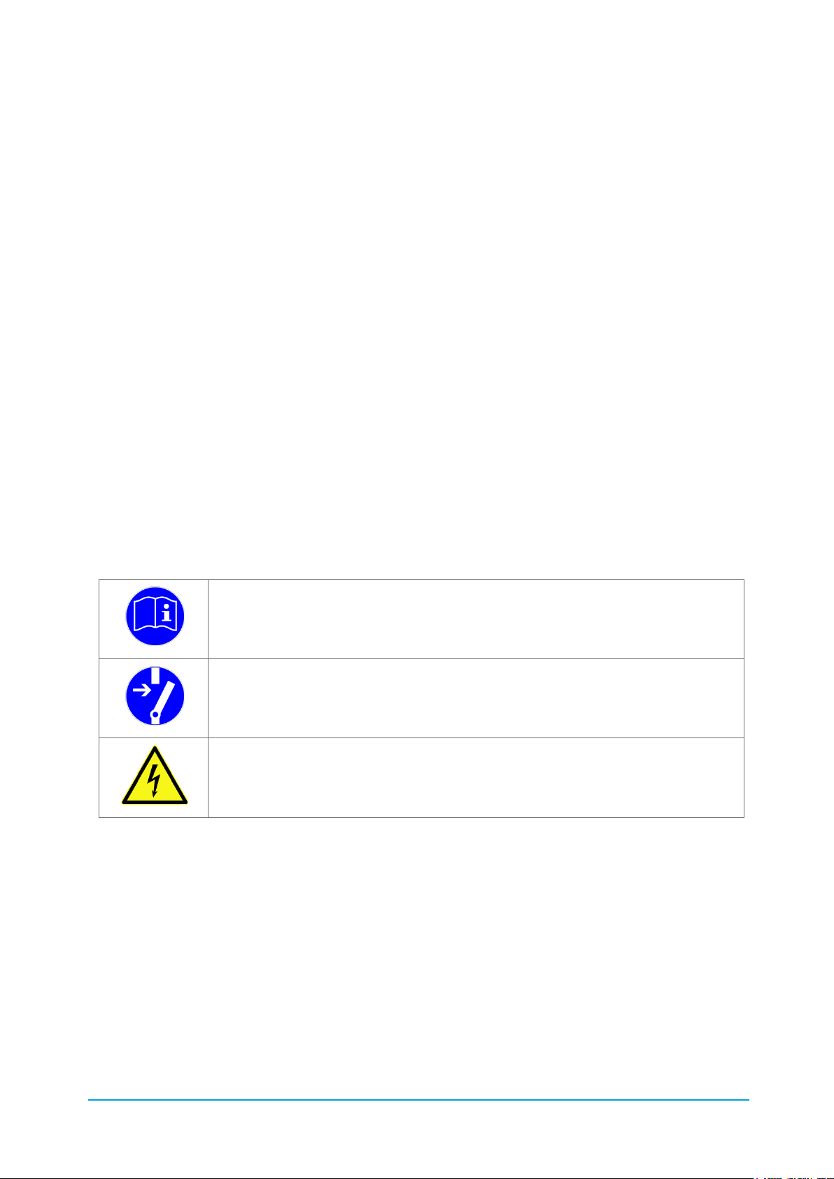
Table 2: Safety instructions
Note and follow the instructions for use!
Before opening the machine it must be disconnected from the power supply!
After disconnecting the machine from the power supply, always wait for at least
5 minutes before opening it.
Danger! High voltage! If the machine is only switched off at its main switch,
dangerous electrical voltage is still present at several terminals in the control
cabinet.
Page 9

9 / 89 83000102.Ki
Technical data
Table 3: Technical data
Compact-Line
-
cBoxX 30
cBoxX 40
cBoxX 50
cBoxX 60
cBoxX 70
cBoxX 80
cBoxX 90
cBoxX 100
Refrigerating capacity @ tw2=20°C / tu=32°C
kW
34
43
55
68
78
87
95
105
Refrigeration circuit hermetically tight
no
Refrigerant
-
R410A
GWP
2088
Refrigerant capacity
kg 6 6 6 7 8 8 8 8
CO2 equivalent
t CO2
12,5
12,5
12,5
14,6
16,7
16,7
16,7
16,7
Cooling medium (liquid/secondary refrigerant)
-
Water or water / glycol
Ambient temperature range
°C
+5 to +45 (optionally -25 to +50°C)
Liquid feed temperature
°C
+8 to +30 (optionally to -10)
Target constancy
K
+/-1
Tank volume
l
300
500
Coolant circulation, nominal (dt = 5K)
m³/h
5.5
7.2
9.2
11.1
12.4
14.3
16.1
18.2
Free pump pressure (standard)
bar
3
Water connection, nominal size
RP
11/2"
2"
Air flow rate (max.)
m³/h
9350
9350
12600
20000
23270
23270
23270
23270
Sound pressure level at 5 m distance
dBA
62
62
55
69
59
59
59
59
Operating voltage (standard)
V/Ph/Hz
400/ 3/ 50
Protection class
-
IP54
Height
mm
2030
2030
Width
mm
830
830
Length
mm
1240
1840
Net weight
kg
540
540
550
620
650
650
700
720
Gross weight
kg
840
840
850
920
1150
1150
1200
1220
Page 10

10 / 89 83000102.Ki
Compact-Line
-
cBoxX 120
cBoxX 160
cBoxX 180
cBoxX 200
Refrigerating capacity @ tw2=20°C / tu=32°C
kW
135
166
194
210
Refrigeration circuit hermetically tight
no
Refrigerant
-
R410A
GWP
2088
Refrigerant capacity
kg
17
17
23,5
23,5
CO2 equivalent
t CO2
35,5
35,5
49,1
49,1
Cooling medium (liquid/secondary refrigerant)
-
Water or water / glycol
Ambient temperature range
°C
+5 to +45 (optionally -25 to +50°C)
Liquid feed temperature
°C
+8 to +30 (optionally to -10)
Target constancy
K
+/-1
Tank volume
l
700
900
Coolant circulation, nominal (dt = 5K)
m³/h
21,5
27,2
32,2
35,4
Free pump pressure (standard)
bar
3
Water connection, nominal size
RP
DN65 PN10 EN1092
Air flow rate (max.)
m³/h
45550
49100
Sound pressure level at 5 m distance
dBA
67
67
67
67
Operating voltage (standard)
V/Ph/Hz
400/ 3/ 50
Protection class
-
IP54
Height
mm
2030
Width
mm
1200
Length
mm
2665
3965
Net weight
kg
1100
1200
1300
1400
Gross weight
kg
1800
1900
2200
2300
Page 11
11 / 89 83000102.Ki
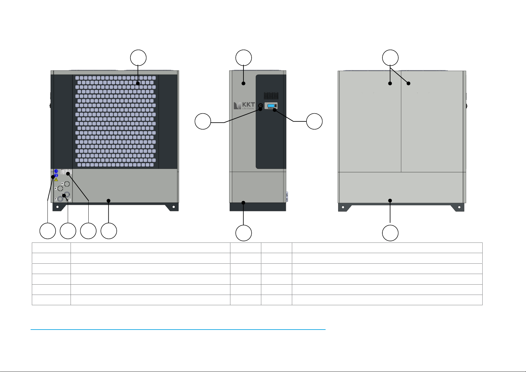
1.2. Elements
1
Metal cladding, top, operator side
a
Safety instructions
2
Metal cladding, bottom, operator side
b
Water connections
3
Metal cladding, top, service side
c
Rating plate
4
Metal cladding, bottom, service side
d
Display
5
Metal cladding, condenser protective grating
e
Main switch
6
Cladding, hydraulics
1 2 3 4 5 6 a b c d e
Page 12

12 / 89 83000102.Ki
1.3. Explanation of terms
A few important terms which appear in this document are briefly explained here for improved
understanding.
Table 4: Explanation of terms
Term
Explanation
Application
The heat source connected hydraulically with the chiller.
Process circuit
Application and piping to the chiller.
Cold water cycle
The process circuit and chiller in hydraulic piping.
Cold water
Cooling medium in the cold water circuit.
Cooling air
Ambient air drawn through the machine, which absorbs the heat.
Net weight
Ready to operate machine without cold water.
Gross weight
Ready to operate machine including cold water.
Page 13
13 / 89 83000102.Ki
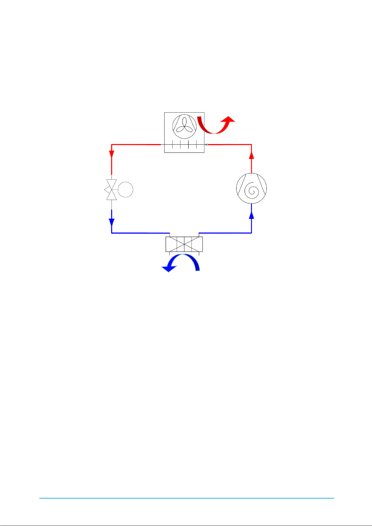
2. Function and main components
The chiller consists of the main components: compressor, condenser, expansion valve and
evaporator, which are arranged in a circuit (Figure 1). Refrigerant circulates in this circuit (cycle).
It absorbs heat from the cold water in the evaporator and gives it up to the ambient air in the
condenser.
Figure 1: C6848 refrigeration diagram
In addition, diverse pressure and temperature sensors, a control unit, a high-pressure switch, one
or more pumps and one or more fans are also installed for control and operation of the chiller.
2.1. Compressor
The compressor generates the pressure difference between the heat sink and heat source in the
refrigerant circuit needed for evaporation and condensing. Coolant vapor from the evaporator is
drawn in and compressed to the condensing pressure in the compressor.
The compressors used operate according to the scroll principle. Scroll compressors are
maintenance-free, quiet and have a very high efficiency.
The flow temperature is controlled by switching on or off one or more compressors (see 8.7.4
Compressor control). Sequential changeover ensures that all compressors are loaded uniformly.
Compressor
Condenser and fan
Evaporator
Expansion
valve
Heat
Cold
Page 14

14 / 89 83000102.Ki
2.2. Evaporator
The evaporator is a plate heat exchanger which transfers heat from the cold water to the
refrigerant. In order for the heat transfer to take place, the refrigerant in the evaporator has a
lower temperature than the cold water and when it absorbs heat it changes its physical state from
liquid to gaseous.
If the cold water is contaminated, deposits can form on the transfer surfaces of the evaporator.
These impair the heat transfer to the refrigerant and reduce the refrigerating capacity of the
machine. For this reason, always ensure the specified water quality and do not use any other
additives than those specified.
2.3. Condenser
The condenser is a microchannel heat exchanger which transfers heat from the refrigerant to the
ambient air. In order for the heat transfer to take place, the refrigerant in the condenser has a
higher temperature than the ambient air drawn in and when it gives off heat its physical state
changes from gaseous to liquid.
Contaminated cooling air can cause deposits to form on the surface of the condenser over time.
This impairs heat transfer to the refrigerant which restricts the operating limit of the machine and
reduces the machine's refrigerating capacity. Please refer to Chapter 9: Cleaning for a description
of how to clean the condenser. If you operate your chiller in an environment containing dust or oil
vapour, use the optionally available air filter mat (see 3.19 Air filter mat).
In case that there already is an existing house water system and the warm condensing air has to
be avoided, the chiller can also be specified with a water cooled condenser (see 3.3 Version with
water cooled condenser)
2.4. Expansion valve
The expansion valve controls the admission of liquid refrigerant to the evaporator and at the
same time restricts the pressure of the refrigerant before it enters the evaporator. With this
restriction the refrigerant cools to the evaporation temperature.
The expansion valve used in your machine is controlled electronically. The electronic control
ensures that the evaporator is always optimally supplied with refrigerant. This improves the COP
(Coefficient of Performance) and reduces pressure fluctuations in the refrigeration circuit.
2.5. Refrigerant
The refrigerant R410A circulates in the refrigeration circuit. It conveys heat from the evaporator to
the condenser and at the same time continuously changes its physical state.
R410A is a fluorinated greenhouse gas consisting of the zeotropic mixture of 50% R32 and 50%
R125 with virtually negligible temperature glide. R410A has a very high volumetric refrigerating
capacity and has no ozone depletion potential (ODP=0). A corresponding safety data sheet can be
obtained from our KKT chillers Service Team (see Table 1: Contact details).
Page 15

15 / 89 83000102.Ki
2.6. Oil
The components of the compressor subject to friction are lubricated by oil, which is added to the
refrigerant in the factory. The polyolester-160SZ is used for this. The oil is soluble in the
refrigerant and is distributed with it throughout the refrigeration circuit. The total oil quantity of
the respective unit is given in the technical data. A corresponding safety data sheet can be
obtained from our KKT chillers Service Team (see Table 1: Contact details).
2.7. Filter dryer
The task of the filter dryer is to absorb any contamination or moisture from the refrigerant circuit.
Both refrigerant and oil are hygroscopic. When the refrigeration circuit is installed the oil can
absorb moisture. This moisture can cause corrosion and has a negative effect on the cooling
process. The filter dryer bonds this moisture and also has a mechanical filter effect. If work is
carried out on the refrigeration circuit requiring it to be opened, the filter dryer (cBoxX 30 –
cBoxX100) respectively the filter cartridge (cBoxX 120 – cBoxX 200) must be replaced.
2.8. Pressure sensors
The pressure sensors used are compact pressure transmitters with piezoresistive measuring cell.
The sensors register the system pressure continuously in different places within the refrigerant
and cold water circuit. The values are used to control the system and for visualisation at the
controller display.
2.9. Temperature sensors
The temperature sensors used are equipped with a platinum measuring cell. The sensors register
the temperature continuously in different places within the refrigerant and cold water circuit. The
values are used to control the system.
2.10. Control unit/ main circuit board
The control unit is programmed in the factory. All system readings and information come together
on it. In addition, the electrical components are controlled via algorithms.
2.11. Display
The display is used to visualise the information required by the operator and the system
processes. It is also possible to make entries at it. The display communicates with the control
unit. Further information on operation is given in Chapter 8.5 Control panel).
Page 16
16 / 89 83000102.Ki
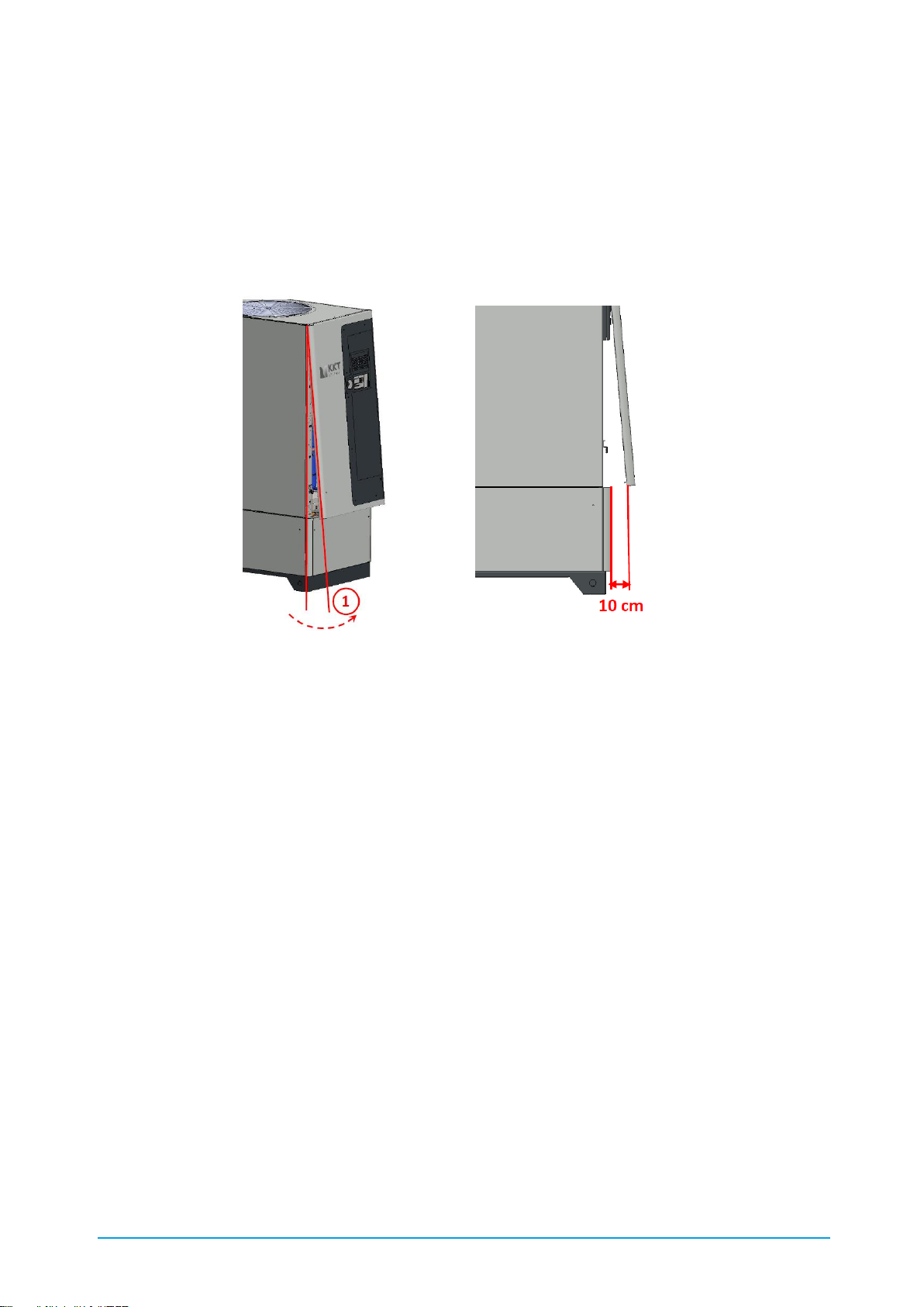
2.12. Control cabinet
The control cabinet conforms to the requirements of EN 60204 and contains the electrical and
electronic components for controlling the chiller. After removing the operator control panel the
control cabinet is accessible and can be opened using a standard two-way key. In order to avoid a
damage of the main switch while demounting the side panel, the side panel has to be tipped
10cm on the bottom side. A circuit diagram is supplied with the unit.
Figure 2: Demounting the side panel of the switch cabinet
2.13. Pump
The chiller's pump ensures the necessary circulation of the cold water. The water is drawn out of
the chiller's internal tank and is pumped through the process circuit. Optionally, the units can also
be designed as a continuous flow cooler without tank, with pump or without tank, without pump
(see Chapter 3.1 Version without tank, with pump, and Chapter 3.2 Version without tank, without
pump).
2.14. Fan
The fan draws the cooling air from the surroundings through the condenser and blows out the
heated air upwards out of the chiller. To prevent injuries, the fan is protected against accidental
contact by protective grilles. The fan's speed is variable and is controlled by the main printed
board. The speed of the fan is essentially controlled by the condensing pressure. The fan is
protected against thermal overload. In units with two fans the speed of fan 1 is always the same
as the speed of fan 2.
2.15. Cold water cycle
The cold water is drawn out of the chiller's internal tank by the internal pump and is pumped
through the process circuit. Optionally, the units can also be designed as a continuous flow cooler
without tank, with pump or without tank, without pump (see Chapter 3.1 Version without tank,
with pump, and Chapter 3.2 Version without tank, without pump). In the process circuit the cold
Page 17
17 / 89 83000102.Ki
water absorbs heat. The circuit closes when the cold water is pumped back into the chiller. It
flows through the evaporator, in which it gives off heat. The cold water then passes back into the
tank. The cycle begins again.
2.16. Materials used in the water circuit
The material composition of the standard equipment is shown in Table 5:
Table 5: Materials used - standard version
Component
Material (cBoxX 30 – cBoxX 100)
Unit connections
V2A 1.4305
Hose
Synthetic rubber
Evaporator
V2A 1.4301 and copper (99.9%)
Tank
Tank ports/connection sockets
V2A 1.4301
V4A 1.4571
Pump
Mechanical seal
Grey cast iron and V2A 1.4301
EPDM
Sealing plugs, yellow
Polyamide PA 6
Sealing plugs, black
Polyoxymethylene (POM)
Filling and drain cock
Nickel-plated brass
Bends, tees, couplings
Gunmetal CC499K
Fittings
V4A 1.4408
Hose nozzles
Nickel-plated brass
Swivelling elbow threaded coupling
(level indicator)
PVC and nickel-plated brass
Temperature sensor PT1000
V2A 1.4301
Pressure sensor XSK AC10I-U188
V2A 1.4301
Overflow valve (optional)
Gunmetal
Tank heater (optional)
Nickel-chrome-iron alloy 825
Component
Material (cBoxX 120 – cBoxX 200)
Unit connections
ABS
Piping and fittings
ABS
evaporator
V2A 1.4301 and copper (99,9%)
Tank
Tank ports/connection sockets
V2A 1.4301
V4A 1.4571
Pump
Mechanical seals
Grey cast iron and V2A 1.4301
EPDM
Sealing plugs, yellow
Polyamide PA 6
Sealing plugs, black
Polyoxymethylene (POM)
Filling and drain cock
Nickel-plated brass
Swivelling elbow threaded coupling
(level indicator)
PVC and nickel-plated brass
Page 18
18 / 89 83000102.Ki
If equipped with the optional Water circuit in non-ferrous metal-free version the material
composition is as shown in Table 6:
Table 6: Materials used for the non-ferrous metal-free version
Component
Material (cBoxX 30 – cBoxX 100)
Unit connections (rotating parts)
V2A 1.4305
Hose
Synthetic rubber
Evaporator
V2A 1.4301
Tank
Tank ports/connection sockets
V2A 1.4301
V4A 1.4571
Pump
Mechanical seal
V2A 1.4301
EPDM
Sealing plugs, yellow
Polyamide PA 6
Sealing plugs, black
Polyoxymethylene (POM)
Filling and drain cock
V4A 1.4401
Fittings
V4A 1.4408
Hose nozzles
V4A 1.4408
Elbow threaded couplings
(level indicator)
PVC and polyoxymethylene (POM)
Hose (level indicator)
PE natural
Temperature sensor PT1000
V2A 1.4301
Pressure sensor XSK AC10I-U188
V2A 1.4301
Overflow valve (optional)
V2A 1.4301
Tank heater (optional)
Nickel-chrome-iron alloy 825
Component
Material (cBoxX 120 – cBoxX 200)
Unit connections
ABS
Piping and fittings
ABS
evaporator
V2A 1.4301
Tank
Tank ports/connection sockets
V2A 1.4301
V4A 1.4571
Pump
Mechanical seals
V2A 1.4301
EPDM
Sealing plugs, yellow
Polyamide PA 6
Sealing plugs, black
Polyoxymethylene (POM)
Filling and drain cock
V4A 1.4401
Swivelling elbow threaded coupling
(level indicator)
PVC und polyoxymethylen (POM)
Hose for level indicator
PE nature
Temperature sensor PT1000
V2A 1.4301
Page 19

19 / 89 83000102.Ki
2.17. Water quality
The following limits must be maintained for safe operation of the equipment:
Table 7: Water quality
Property /
components
Unit
Value range
Standard version
Value range
Non-ferrous metal-free version
pH value (20 °C) - 7-9
6-9
Saturation index
-
-0.2 < 0 < +0.2
-0.2 < 0 < +0.2
Conductivity
µS/cm
80-500
5-500
Water hardness
°dH
<5.6
<5.6
Carbonate hardness
mol/m³
<0.5
<0.5
Total plate count
K/ml
<10,000
<10,000
Grain size
µm
< 250
< 250
Glycol fraction (AFN)
% by vol
20-40
20-40
Oil fraction
% by vol
0
0
Chloride (Cl-)
mg/l
<50
<50
Sulphate
mg/l
<50
<50
Nitrate
mg/l
<100
<100
Copper
mg/l
<0.1
<0.1
Iron
mg/l
<0.2
<0.2
Free carbonic acid
mg/l
<20
<20
Manganese
mg/l
<0.1
<0.1
Ammonia
mg/l
<2
<2
Free chloride
mg/l
<0.5
<0.5
Sulphide
mg/l
<0.03
<0.03
In order to avoid a restriction of the plate heat exchanger the above listed limit values have to be
guaranteed imperatively.
Furthermore mucilage bacteria are not allowed in the cooling water. If that is not possible, KKT
chillers can recommend an accordant inhibitor based on a biologic water analysis.
Page 20

20 / 89 83000102.Ki
2.18. Permitted cooling media
Water and mixtures of water / Antifrogen N (AFN) or water / Antifrogen L (AFL) according to the
details given in Chapter 2.17 Water quality. The following table shows the requirements for the
mix ratio of water with the antifreezes AFN or AFL. To maintain the performance of your machine
and prevent damage to components, these values must be maintained as precisely as possible.
Table 8: AFN and AFL mix ratios (or equivalent)
Setting
Frost-free at
t-environment to
AFN mix ratio
AFL mix ratio
Glycol 20 - 25 %
-10°C
20-25 %
25-30 %
Glycol 30 - 35 %
-15°C
30-35 %
32-37 %
Glycol 40 %
-25 °C
40 %
42 %
3. Options and accessories
The chiller can be equipped in the factory with the options described in the following.
The items marked "accessories" are enclosed with the unit, unattached, and can be reordered at
any time using the appropriate product number. The installer of the machine is responsible for
installing the accessories. You can also ask our KKT chillers Service Team to arrange for this
installation (see Table 1 Contact details).
Details of your machine's equipment are given in the separate summary documentation.
3.1. Version without tank, with pump
The Compact-Line units are also optionally available as continuous flow chillers. In this case the
units are delivered without an internal tank. The temperature sensor is then located in the
chiller's return line. If a tank open to the atmosphere is integrated on site, it is necessary to
ensure that the tank is not installed at a lower level than the chiller. Additional pressure losses
between the tank on site and integrated pump must be avoided (dp
max
=0.3bar)
3.2. Version without tank, without pump
The Compact-Line units are also optionally available as continuous flow chillers. In this case the
units are delivered without an internal tank and without pump. The temperature sensor is then
located in the chiller's return line. The cold water is then circulated via the evaporator by a pump
to be installed on site. This must at least be designed to the pressure loss of the overall system.
ATTENTION! Do not mix different antifreezes. This can cause unwanted chemical
reactions and silting up.
Page 21
21 / 89 83000102.Ki
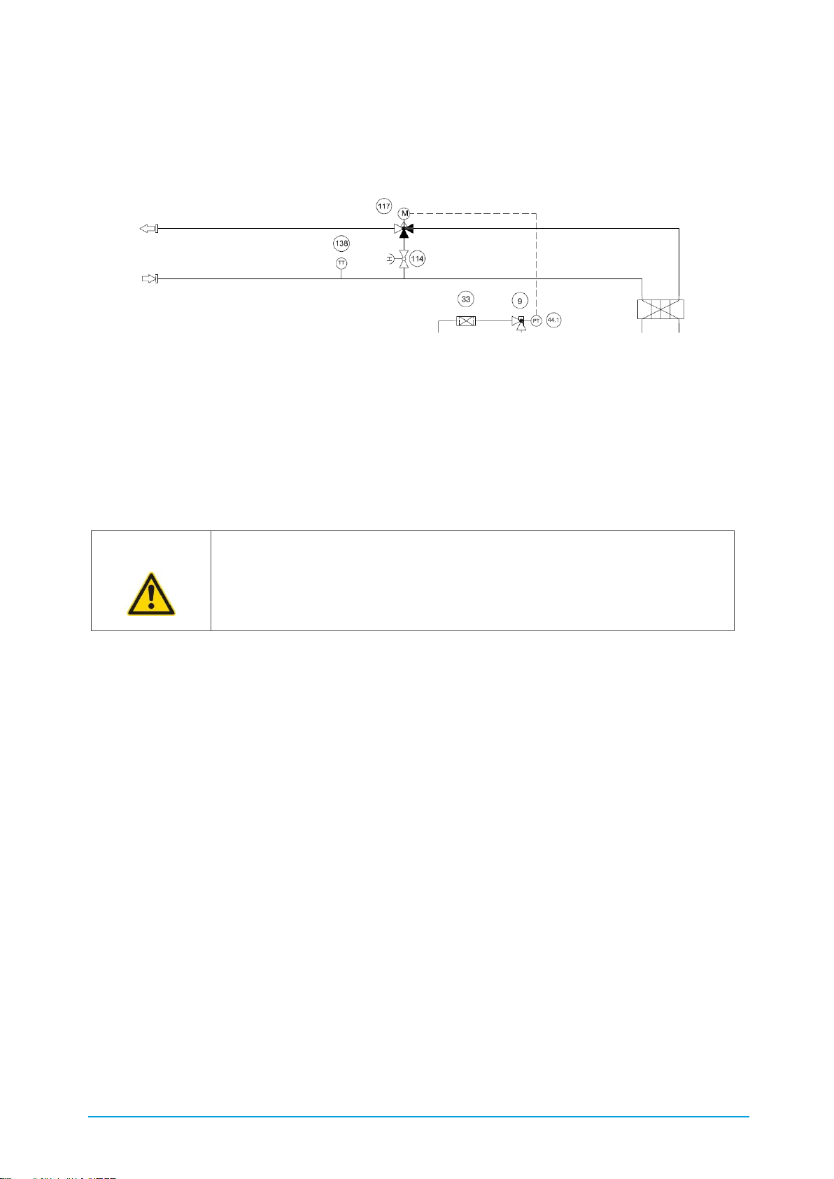
3.3. Version with water cooled condenser
Whereas the basic versions of the Compact-Line is specified with an air cooled condenser, the
units are also available with an water cooled condenser.
Thereby the condenser is a plate heat exchanger with copper brazed stainless steel plates. The
3way valve is mounted in the cooling water outlet and is adjusted by an actuator depending on
the condensing pressure. The operation mode can be switched from the 3way operation to a
2way operation by closing the pre mounted bypass valve. The cooling water temperature is
measured by an additional temperature sensor in the cooling water inlet and is shown at the
controller display.
The project specific data as well as the adapted hydraulic scheme and the dimension sketch can
be found in the additional short documentation.
3.4. Heater for compressor and control cabinet
The oil sump heater prevents refrigerant from becoming deposited in the oil of the compressor at
low ambient temperatures. When the compressor is started up this refrigerant would be liberated
from the oil as gas and make the oil foam up. Under these basic conditions the lubrication of
components in the compressor subject to friction would be poor and the compressor could be
damaged.
The control cabinet heating is controlled thermostatically and, at low ambient temperatures, it
prevents moisture from the ambient air drawn in condensing on the electrical and electronic
components of the cabinet thereby damaging them.
For both heaters to be active, the chiller must not be disconnected from the power supply (8.2
Selecting the operating mode).
3.5. Insulation of the cold pipes and the pump(s)
To prevent condensation on cold chiller pipes, where high temperature differences exist between
the surroundings and cold water flow and taking into account the relative humidity the option of
insulation of the cold pipes must be specified.
The water quality shown in Table 7: Water quality has to be guaranteed imperatively –
the manufacturer does not assume liability for damages caused by other water
qualities.
Page 22
22 / 89 83000102.Ki
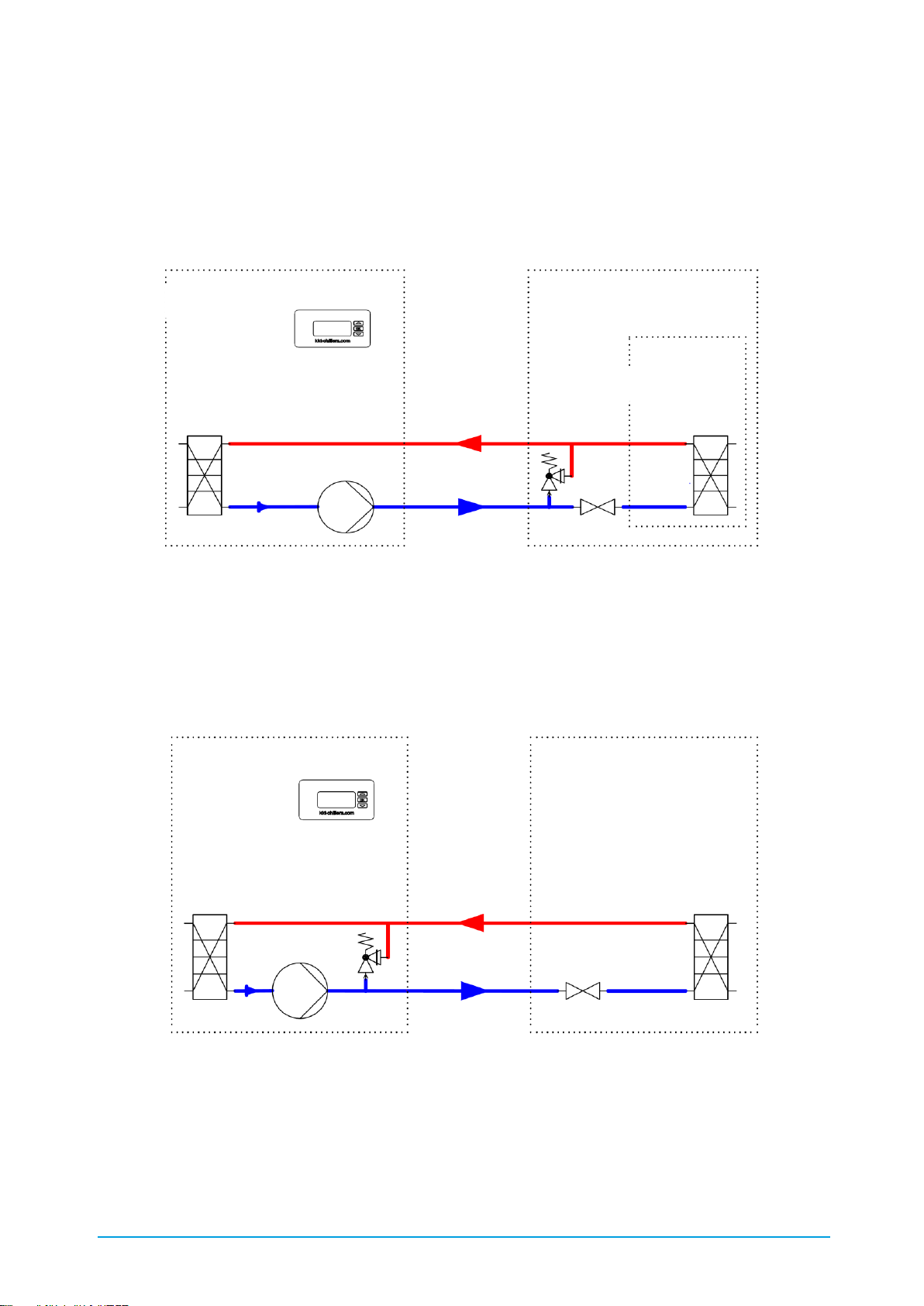
3.6. Tank heater with thermostatic pump start
The tank heater maintains a minimum temperature in the tank. The pump circulates the cold
water, while the tank heater controls the temperature in the system. We recommend a hydraulic
installation as shown in Figure 3. Any bypass valves must therefore always be installed frost-free.
For the heater to be active, the chiller must not be disconnected from the power supply. Even if
the external release (8.3 External release) is deactivated, the pump remains active.
Figure 3: C6856 thermostatic pump start with overflow valve (recommended installation)
3.7. Overflow valve for standby mode
The optional overflow valve should be installed if it is possible for the flow of the cold water to
reduce sharply or be completely prevented while the unit is running. The internal overflow valve
ensures the minimum volumetric flow through the chiller and therefore prevents the pump from
switching off. Figure 4 shows the position of the internal overflow valve.
Figure 4: C6863 overflow valve for standby mode
3.8. Higher pressure pump
The standard Compact-Line units have a 3 bar pump, which is designed for the nominal
volumetric flow of the respective unit. Optionally the units can also be built with higher pressure
pumps, within the limits of the minimum or maximum volumetric flow (1.2 Technical data). The
pump characteristic curve of the pump(s) used in your unit is enclosed with the unit.
cBoxX
Frost-free area
Application
Application
cBoxX
Page 23

23 / 89 83000102.Ki
3.9. Second consumer circuit
The standard Compact-Line units have a 3 bar pump, which is designed for the nominal
volumetric flow of the respective unit. If several consumers with different water specifications are
to be cooled with one unit, the unit can also be supplied with an optional second cold water
circuit. Ask your KKT chillers contact.
3.10. Additional evaporator pump
The evaporator is optimised for the nominal volumetric flow rate of cold water. The nominal
volumetric flow rate is given in Table 3 Technical data.
If the operating volumetric flow rate of the cold water is more than 50 % smaller, an evaporation
pump must be installed. The evaporator pump circulates the cold water internally and keeps the
storage water at feed temperature. A second pump supplies the process circuit with cold water.
3.11. Automatic water feed
Any leaks and evaporation can cause the quantity of cold water available for the chiller function to
reduce during the course of operation of the chiller. The Automatic water feed option provides the
possibility of topping up the cold water circuit automatically. The tank contents are monitored
continuously and if necessary topped up until it has again reached the optimum level. In this case
the operator only has to connect the chiller to the building's water system via the feed connection
(see Figure 5). The inlet pressure must lie between 1 bar and 10 bar.
Figure 5: Top-up connection
If you operate your chiller with a mixture of water / glycol and top up only with pure water, you
must check the glycol content of the circuit water at regular intervals and if necessary adjust it.
3.12. Water circuit in non-ferrous metal-free version
If your machine is a non-ferrous metal-free version, all parts of the chiller's cold water circuit in
contact with the media are free from non-ferrous metals. Certain components such as the
evaporator and pump are suitably modified. The materials used in the water circuit are listed in
Table 6.
3.13. DI package
The DI package contains the non-ferrous metal-free option for the water circuit (see chapter,
3.12) and a replaceable DI cartridge with conductivity monitoring and control.
3.14. Special voltage
The special voltage option describes the use of the aggregate outside the voltage supply of 400V
(±10%)/3phases/50Hz. Here alternative components (e.g. compressors, pumps or fans) as well
as an autotransformer (integrated or unattached) can be used.
Page 24

24 / 89 83000102.Ki
For chillers with an integrated autotransformer sizes cBoxX 30 to cBoxX100, the transformer is
located in an additional flanged-mounted housing; for sizes cBoxX 120 to cBoxX 200 it is located
in the existing housing. For exact specifications, please refer to the circuit diagram. Please get in
touch with your KKT chillers contact person for further information on implementing this option.
3.15. Phase monitoring
The Compact-Line units can be equipped with optional phase monitoring. This monitors the phase
sequence, phase failure, undervoltage and asymmetry and covers a voltage range of 200-690V. If
the respective predefined limits are exceeded the system switches off and protects the electrical
components installed in the unit.
3.16. Hot gas bypass for output control <1K
If a more precise target constant than ±1 Kelvin is required, the chiller can be equipped with an
output control. In this case the output of the refrigeration circuit is adjusted to the cooling
demand by an electronically controlled valve. Unlike the standard control by switching
compressors on or off, a higher target constant is achieved by the continuous regulation of the
valve.
3.17. High-temperature package
In principle, the units must be operated within the given ambient temperature range (see
Table 3). If the high-temperature package is selected, the unit can be operated at an ambient
temperature of up to 50 °C without high-pressure faults.
3.18. Special paint finish
While the condenser's protective grille is always painted in RAL 7015 anthracite black, the
cladding panels (1.3 Elements) can also be optionally finished in special colours.
3.19. Air filter mat (accessories)
If the chiller is operated in surroundings with dust or oil vapour the condenser should be
protected with the air filter mat. The filter is fixed using the Velcro tapes attached in the
condenser protective grille. The filter is cleaned by removing it and washing it with water or a
slightly alkaline solution. Heavily-contaminated filters must be replaced by new ones. Please
contact the KKT chillers Service Team (see Table 1 Contact details).
3.20. Levelling feet (accessories)
The levelling feet are used for vibration isolation and for height adjustment. They consist of a
threaded rod and a grey cast iron shell with an elastic element attached. The threaded rod
enables the height to be adjusted and compensates for floors sloping by up to 5°. The elastic
element has a slip-resistant covering. Figure 6 and Figure 7 show the installed machine foot – the
technical drawing is given in the appendix.
Page 25

25 / 89 83000102.Ki
Figure 6: Machine base (foot) – outside view
Figure 7: Machine base (foot) - mounting on the baseplate
3.21. Level package (accessories)
The level package is used if the application is to be installed more than 500 mm above or below
the chiller (see also Chapter 6.2.7 Process level). This option is delivered uninstalled and consists
of an electronically controlled valve and a non-return valve. The electronically controlled valve
must be installed at the unit inlet, the non-return valve at the unit outlet. The electronically
controlled valve is installed electrically in the control cabinet as shown in the circuit diagram.
3.22. Filter assembly group coolant circuit (accessories)
The water filter protects the coolant circuit against dirt. The set, consisting of a filter, fitting and
two shut off valves, is enclosed with the chiller in a separate pack and must be fitted onto the
cold water inlet of the chiller from the outside when the chiller is installed.
3.23. Filter assembly group cooling water circuit (accessories)
The water filter protects the cooling water circuit against dirt. The set, consisting of a filter, fitting,
two shut off valves and two pressure gauges for displaying the cooling water inlet- and outlet
pressure is enclosed with the chiller in a separate pack. The installation can be either mounted
for shutting of the filter group or for shutting of the complete cooling water circuit.
Page 26

26 / 89 83000102.Ki
3.24. MultiplexX connection group (accessories)
If the refrigerating capacity of a chiller is not sufficient, several units of the same type can be
combined in the version with tank and pump. A MultiplexX connection group can be ordered for
this purpose and consists of the level package (3.21 Level package) and a corresponding
connection kit for the flow balance between the tanks. The refrigerating capacity of the individual
units can then be added together. Please contact your KKT chillers contact to arrange the
appropriate project planning for this option.
3.25. Refill cartridge R410A (accessories)
Chillers with refrigerant capacity >12kg must be declared as dangerous goods in accordance with
UN2857 (5.1 Dangerous goods). The optional R410A refill cartridge is available for units with
refrigerant capacities >12kg (cBoxX 120- CBoxX 200) so that you do not incur any additional
logistics costs. Following the performance check in the factory, a quantity of refrigerant is filled in
a certified refrigerant cylinder so that the 12kg limit is kept to in the unit. The refill cartridge is
then delivered together with the unit. The refrigerant quantity drained for transport can be
returned to the system as part of the commissioning using the summary description provided with
the refill cartridge.
3.26. Anybus-Gateway (accessories)
The Anybus-Gateway is ready mounted in the switch cabinet and can be used as an interface for
processing all chiller signals. Therefore the following processing protocols are available
depending on the customer specification:
▪ Modbus
▪ Profibus
▪ CANopen
▪ Profinet
▪ Devicenet
▪ EtherNet
▪ EtherCAT
▪ ControlNet
▪ CC-Link
A Modbus TCP communication is already included on the display pcb as a standard feature. An
Anybus gateway is not required.
Page 27

27 / 89 83000102.Ki
3.27. Remote Control Panel (accessories)
For the case that the chiller shall be operated not from the machine itself but from a different
operating place the chiller can be delivered with a remote control panel. Thereby the same display
is mounted together with the operating voltage supply in one miniature housing. The remote
control panel is connected to the chiller with clips and takes over the complete function of the
controller in the main device. By switching the accordant bridge integrated in the control cabinet,
the required operating place can be chosen.
(in = internally installed control / out = outward leading control)
3.28. Special languages (accessories)
These instruction manuals are provided in German, English, French and Spanish. Other languages
are available on request.
3.29. Wooden Crate (accessories)
Whereas the chillers of the Compact-Line are delivered on a wooden palette with Styrofoam
corners stretched in the foil as a standard, the chillers can be also ordered in a wooden crate.
There the chillers are protected additionally by a wooden crate with IPPC-Label according ISPM
15.
3.30. Seaworthy crate packaging (accessories)
Seaworthy crates for the Compact-Line are produced according to International Standards for
Phytosanitary Measures with packaging made of solid wood (ISPM 15). This means that the
crates are made of heat-treated solid wood which has been stripped of its bark. Only wood-based
materials, such as OSB boards, are used. In addition, all crates are marked with the IPPC logo
and registration number. The units are fixed in the crate with the help of coach bolts, ring nuts
and polyester straps and are packed in a sea air consistent foil with desiccant. The components
used to pack the units can be dismantled using a cross-head screwdriver.
3.31. Water Pump Redundancy
Depending on the optional configuration, the cboxX (water chiller) can be equipped with a dual
water pump for redundancy and increased life time of the pump itself. The operating hours of the
pumps are programmable and can be shared by both pumps (f. e. 24h switch on/off between
both pumps). In case of a pump defect, an automatic switch to the pump redundant, ensures the
continuation of the water chiller and the operation of the end customers application.
3.32. Closed Water Loop
The water chiller is designed as a closed water loop system with an expansion tank. The
expansion tank is pressurized in accordance with the volume of the entire system volume
(including installation). The expansion tank balances temperature swings and related system
pressure of the water loop. In case the coolant temperature rises the expansion tank takes in the
expanded volume of the coolant and if the coolant temperature falls the stored volume will be
released back into the loop again.
Advantages of a closed water loop system are:
Page 28

28 / 89 83000102.Ki
- No top up or refill required, due to no evaporation of the coolant
- No dirt or algues in the coolant
- No cleaning required of the tank
- Reduces weight of the chiller
Page 29

29 / 89 83000102.Ki
4. Safety
Provided it is used as intended, the chiller is designed to operate safely, provided also that the
instructions concerning transport, installation, commissioning/startup and maintenance given in
these operating instructions are complied with. The machine conforms to the safety standards in
accordance with the EC Declaration of Conformity (see Appendix III).
4.1. General information
The chiller contains a high-pressure circuit. The maximum pressure that occurs is 45 bar. Even
when inactive or disconnected from the power supply the circuit is still under pressure.
4.2. Hazard warnings
A number of warning labels are applied to the machine. Keep these warnings clean at all times.
Damaged or missing warnings must be replaced.
Page 30

30 / 89 83000102.Ki
Table 9: Definition of the safety symbols
Note and follow the instructions for use!
Before opening the machine it must be disconnected from the power supply!
After disconnecting the machine from the power supply, always wait for at
least 5 minutes before opening it.
Danger! High voltage! If the machine is only switched off at its main switch,
dangerous electrical voltage is still present at several terminals in the control
cabinet.
Wear foot protection!
Wear hand protection!
Wear eye protection!
Wear protective clothing!
Warning! Hot surface!
Warning! Cold surface!
ATTENTION!
Contains pressurised gas!
Page 31

31 / 89 83000102.Ki
In particular, the following hazard warnings apply to the machine:
Table 10: Hazard warnings
ATTENTION! Work on the chiller must be carried out by properly qualified,
competent personnel!
The surfaces of pipes and components of the refrigerant and cold water
circuit and electrical equipment can be very hot during operation and even
for a while after.
The surfaces of pipes and components of the refrigerant and cold water
circuit and electrical equipment can be very cold during operation and even
for a while after.
ATTENTION! Pipes and components of the refrigerant and cold water circuit
are pressurised.
ATTENTION! Do not undo the system parts. Risk of injury on contact.
ATTENTION! Only use the specified liquids!
WARNING! The device frame as well as the housing have not been designed
for additional loads, which is why it is not permitted to enter or place any
additional loads on the components!
Do not enter No additional loads
Page 32

32 / 89 83000102.Ki
4.3. Residual energy
Even if all the hazard warnings in the chapter above are taken into account, the following residual
energy situations can result in a hazard:
▪ Rotational energy of the decelerating fan
o Despite the installed protective grille, hair or pieces of clothing can still be drawn
in and caught.
▪ Hot surfaces on machine parts
o Especially the compressor head and the hot gas pipe and the condenser can still
be very hot for some time after the machine has been switched off. Temperatures
within the range from 60°C to 90°C are possible.
▪ Dangerous electrical voltage in the control cabinet despite the switched off main switch
o If the machine is only switched off at its main switch, dangerous electrical voltage
is nonetheless still present at several terminals in the control cabinet. In
particular, these are the main supply terminal and the input terminals of the main
switch.
▪ Refrigeration circuit is pressurised
o Provided it is not damaged the refrigeration circuit is closed. Therefore, a hazard
is not to be assumed.
Note:
After switching off the unit at the main switch, if you wait for 5 minutes before opening the unit
risks due to rotational energy and electrical power can be reduced. In this case only the residual
thermal energy must be considered.
Page 33
33 / 89 83000102.Ki
4.4. Safety devices, guards and safeguards
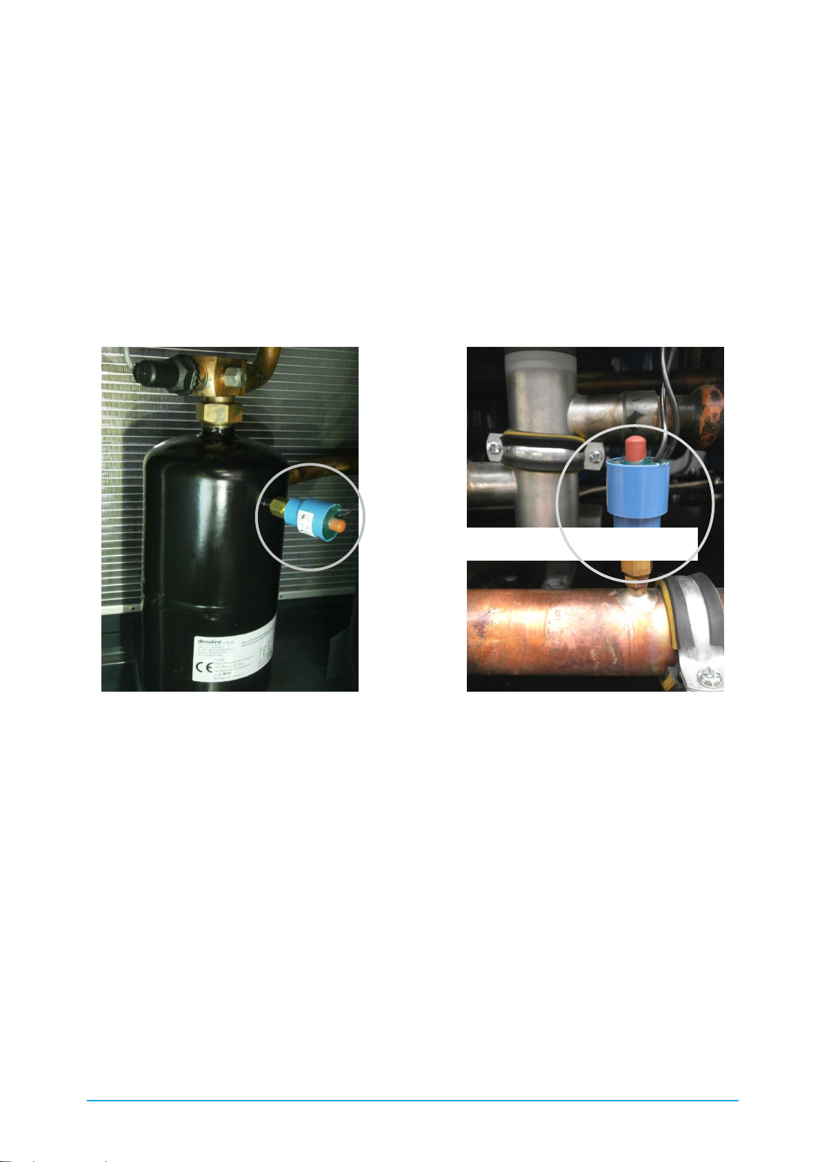
4.4.1. High-pressure limiter
The high-pressure limiter (PZH) is a pressure switch with manual reset. The PZH limits the
condensing pressure and switches off all compressors via their load contactors when the
maximum permitted system operating pressure is reached. It is part of the safety chain. The PZH
is installed on the refrigerant collector for the chiller types cBoxX 30 – cBoxX 200 and on the fluid
pipe for the chiller types cBoxX 120 – cBoxX 200 (see Figure 8: Position of the high-pressure
limiter (PZH)). If the PZH has triggered, a message appears at the operator control terminal. In
this case, please follow the instructions in the Troubleshooting chapter (see Appendix 0).
High pressure limiter (PZH) High pressure limiter (PZH)
cBoxX 30 – cBoxX 100 cBoxX 100 – cBoxX 200
Figure 8: Position of the high-pressure limiter (PZH)
High-pressure limiter (PZH)
Page 34

34 / 89 83000102.Ki
4.4.2. High-pressure monitoring
If the high pressure in the refrigeration circuit of your machine increases to a maximum value, the
compressors are switched off via the High-pressure limiter (see Chapter 4.4.1 High-pressure
limiter). A manual reset is required. The high-pressure monitoring on the other hand reduces the
compressor output before the PZH's switch-off value is reached. This is done by successive
switching off of one or more compressors. A message appears at the control panel. When the
high pressure has reduced to a minimum value of 31.5 bar, the compressors are released once
more. In most cases partial shutdown of the compressors enables operation of the chiller to be
maintained with reduced output. If the high-pressure monitor has triggered, please follow the
instructions in the Troubleshooting chapter (see Appendix 0).
4.4.3. Low-pressure monitoring
If the low-pressure in the refrigeration circuit of your system is too low for the specified cooling
medium there is a risk of freezing. For this reason the low pressure is monitored continuously and
if it falls below a minimum value, one or more compressors are switched off successively. A
message appears at the control panel. If the low pressure has increased to a minimum value the
compressors are released once more. In most cases partial shutdown of the compressors
enables operation of the chiller to be maintained with reduced output.
If the low-pressure monitor has triggered, please follow the instructions in the Troubleshooting
chapter (see Appendix 0).
4.4.4. Flow monitoring
If the volumetric flow of the cold water which is pumped through the evaporator is too low, there
is a risk of freezing. For this reason the flow through the evaporator is monitored continuously. If
the volumetric flow rate is only around 50 % of the nominal volumetric flow rate, the message
"Flow warning" appears.
If the rate falls below the minimum value of 20 % the compressors are switched off and the
message "Flow stop“ appears. In this case, please follow the instructions in the Troubleshooting
chapter (see Appendix 0).
4.4.5. Personal protective equipment when operating the machine
Operating the machine involves making settings at the control panel. During operation of the
machine its cladding panels are installed, the machine is completely enclosed. No protective
equipment is needed.
We recommend ear protectors be worn by persons with jobs that require them to be continuously
in the immediate vicinity of the chiller. Please refer to the sound emission information included in
the technical data.
Page 35
35 / 89 83000102.Ki
4.5. Personal protective equipment for servicing work
Servicing work on the machine includes all work for which the machine is opened and one or
more cladding panels are dismantled. In particular, this includes cleaning work in accordance
with Chapter 9 Cleaning and maintenance work in accordance with Chapter 10 Service. Before
work is carried out on the chiller the protective equipment described in Table 9: Definition of the
safety symbols must be used.
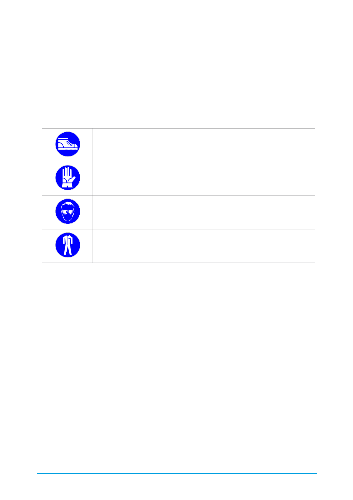
Table 11: Personal protective equipment for servicing work
Wear foot protection!
Wear hand protection!
Wear eye protection!
Wear protective clothing!
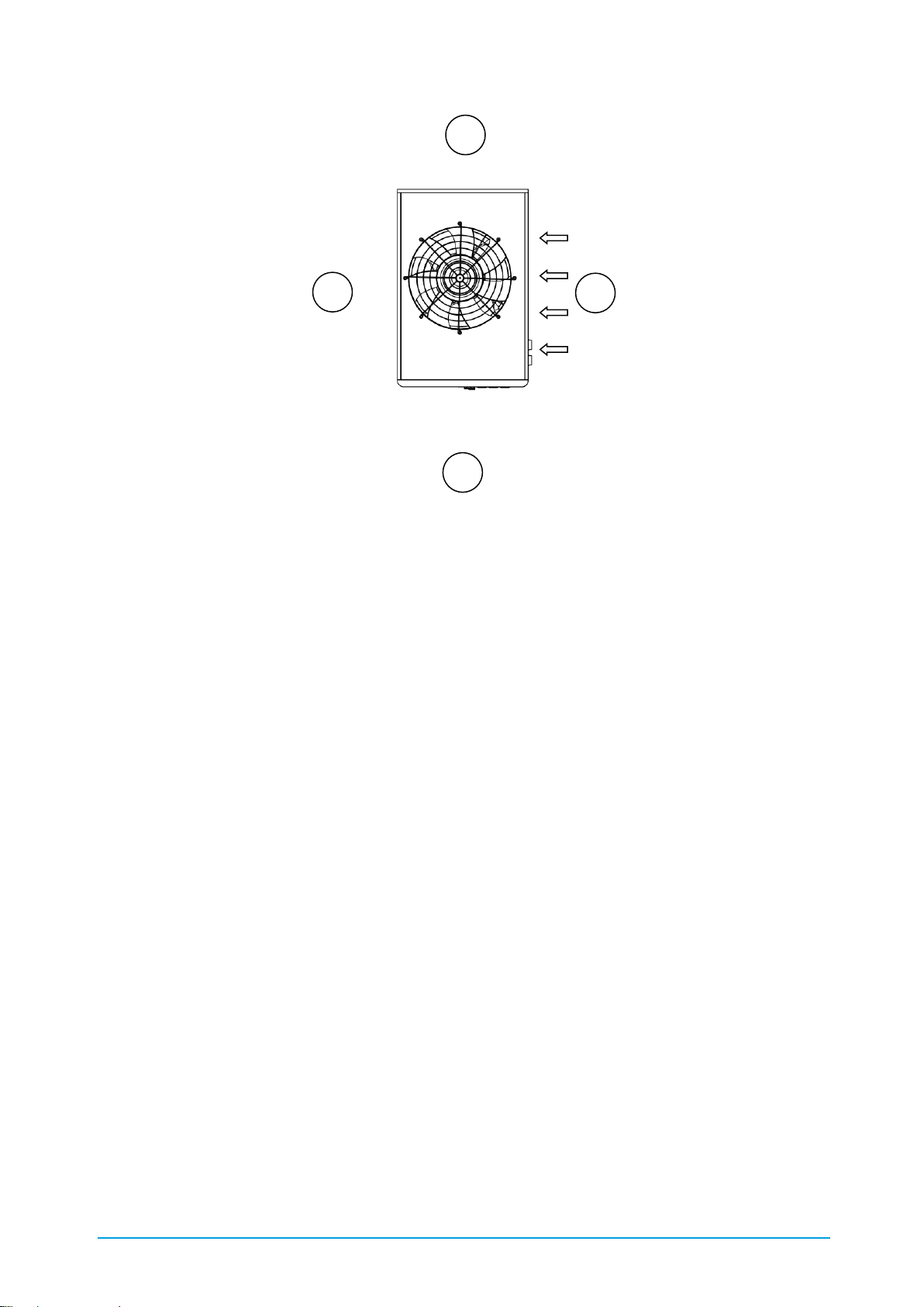
4.6. Airborne sound emissions
The airborne sound emissions data is given as the sound pressure level, measured at a distance
of five metres without reflection. Its maximum value is shown in the technical data. This only
occurs at the highest fan speed at the air intake side of the chiller (Figure 9, measuring point [1]).
The emissions in [2] to [4] are generally around 10 % lower than [1].
Page 36
36 / 89 83000102.Ki
Figure 9: Airborne sound emissions
In partial load mode or under favourable ambient conditions (see Chapter 4.7.1 Noise) the fan
speed and therefore the sound emissions reduce automatically.
4.7. Notes on reducing noise and vibration
4.7.1. Noise
Details of your chiller's airborne sound emissions are given in Chapter 4.6.
To reduce noise pollution caused by airborne sound emissions it is advisable to install the chiller
out of doors and out of the range of workplaces.
If this is not possible we recommend that when the unit is installed attention is paid to ensuring
that the air intake side is not pointed directly at a workplace/workstation.
High ambient temperatures mean high fan speeds and this increases the noise levels produced.
It is advisable not to expose the chiller to direct sunlight or to install it in rooms with high air
temperature. Further information is given in Chapter 6.2 Installation site.
4.7.2. Vibration
The chiller is designed so that the vibrations caused by the compressor are largely isolated by the
chiller's frame.
To minimise the effect of vibration still further it is possible to install the chiller with optionally
available levelling feet (3.20 Levelling feet ). These are fitted with damping elastomers.
1 2 3
4
Page 37
37 / 89 83000102.Ki
4.8. Residual risks
4.8.1. Electrical
If all safety provisions are complied with there is no risk.
4.8.2. Mechanical
If all safety provisions are complied with there is no risk.
Mechanical damage to components or pipes of the refrigerant circuit can cause refrigerant to
leak. Leaking refrigerant can cause cold burns.
4.8.3. Chemical
4.8.4. Other
4.9. Dangerous substances
4.9.1. Refrigerant R410A
First aid measures:
▪ After inhaling: remove victim to fresh air, ensuring your own safety, and keep the person
at rest in a comfortable position. Get medical attention. If the person stops breathing,
give artificial respiration.
▪ Following skin contact: leave clothing that has fused with the skin. Rinse areas damaged
by cold with lukewarm water (never use hot water). Do not rub! Cover with sterile
dressing. Ensure medical treatment is provided.
ATTENTION! Toxic and caustic products are produced by the thermal
decomposition of the R410A refrigerant.
ATTENTION! Do not install in rooms with naked flames or smoke.
ATTENTION! Risk of suffocation if the chiller is installed in a room that is too
small. Please note and follow Chapter 6.2.2.
ATTENTION! In the EU you must follow the provisions of EN378-3. Please also
note and follow the local installation regulations and provisions, especially the
Ordinance on handling water pollutant substances and BGR500 Chapter 2.35.
Page 38

38 / 89 83000102.Ki
▪ Following eye contact: rinse the eyes with clean water or eyewash solution for at least 15
minutes with the eyelids open. Consult an eye specialist.
▪ After swallowing: swallowing is not considered to be a likely risk as the refrigerant in the
surroundings is gaseous.
Notes for the doctor: do not give the patient catacholamine or adrenalin ephedrine preparations.
Fire-fighting measures:
▪ Suitable extinguishing agents: The product itself does not burn. Match the extinguishing
measures to the surrounding fire. Cool containers with sprayed water.
▪ Particular hazards due to the substance, its combustion products or gases formed:
forms toxic and caustic gases and fumes on decomposition.
▪ Special protective equipment for fire-fighting: self-contained or air-line breathing
apparatus and acid-resistant protective suit for deployment in immediate vicinity.
▪ Further information: The effect of fire can cause bursting or explosion of the container.
Ignitable gas-air mixtures possible under certain conditions.
Measures in case of accidental release:
▪ Environmental protection measures: where possible do not allow the product to get into
the environment.
▪ Cleaning procedure: leave the product to evaporate.
Handling and storage:
▪ Handling: fire and explosion protection: heating results in increased pressure and a risk
of bursting. Cool containers at risk with water. Open the containers slowly and carefully.
Personal protective equipment:
▪ Respiratory protection: not necessary if adequate ventilation available. Self-contained or
air-line breathing apparatus within enclosed rooms, if insufficient oxygen supply
available, in case of substantial or uncontrollable release. Only use breathing apparatus
in accordance with the international / national standards. Only use breathing apparatus,
no filtering devices.
▪ Hand protection: chemical-resistant protective gloves. Recommended material: Polyvinyl
alcohol.
▪ Eye protection: close-fitting safety glasses/goggles.
General protection and hygiene measures:
▪ Do not inhale fumes / aerosols.
▪ Do not eat/drink or smoke during work.
Page 39

39 / 89 83000102.Ki
4.9.2. Oil POE 160SZ
First aid measures:
▪ After inhaling: remove victim to fresh air, ensuring your own safety, and keep the person
at rest in a comfortable position. Get medical attention.
▪ Following skin contact: remove soiled, soaked clothing. Wash skin with water. If
symptoms develop, get medical advice.
▪ Following eye contact: rinse the eyes with clean water or eyewash solution for at least 10
minutes with the eyelids open. Consult an eye specialist.
▪ After swallowing: can cause vomiting. Have the mouth rinsed out with water and give the
patient two glasses of water to drink. Get medical advice.
▪ Notes for the doctor: symptomatic treatment and assistive therapy as indicated.
Fire-fighting measures:
Low fire risk. Product only ignites in case of very large heat supply.
▪ Suitable extinguishing agents: match to the surroundings. Carbon dioxide, powder and
foam extinguishing agents. Use water with caution to avoid possibly considerable steam
generation.
▪ Particular hazards due to the substance, its combustion products or gases formed:
irritant fumes are released during thermal decomposition.
▪ Special protective equipment for fire-fighting: self-contained or air-line breathing
apparatus and acid-resistant protective suit for deployment in immediate vicinity.
▪ Further information: The effect of fire can cause bursting or explosion of the container.
Ignitable gas-air mixtures possible under certain conditions.
Measures in case of accidental release:
▪ Environmental protection measures: do not allow the product to get into the sewers or
bodies of water. Absorb with sand, soil or a similar absorbent material. Ensure proper
disposal in containers.
▪ Cleaning procedure: Clean the contaminated area with water. Caution! Slipping hazard!
▪ Further information: Inform the police or competent authorities in case of penetration in
the sewers or bodies of water.
Page 40

40 / 89 83000102.Ki
Personal protective equipment:
▪ Respiratory protection: Not necessary if adequate ventilation available. Self-contained or
air-line breathing apparatus within enclosed rooms, if insufficient oxygen supply
available, or in case of substantial or uncontrollable release. Only use breathing
apparatus in accordance with the international / national standards. Only use breathing
apparatus, no filtering devices.
▪ Hand protection: protective gloves. Recommended material: nitrile rubber.
▪ Eye protection: close-fitting safety glasses/goggles.
Handling and storage:
▪ Handling: avoid lengthy skin contact. Avoid inhaling high concentrations of vapour or
fumes.
▪ Storage: suitable material for containers: mild steel. Tightly close unused containers to
prevent the penetration of moisture. Store away from strong oxidants.
4.10. Reasonably foreseeable misuse
Reasonably foreseeable misuse, for the users of the chiller, means foreseeable use in a way not
intended according to the operating instructions. It is due to foreseeable human behaviour.
The following Dangerous situations can arise due to misuse which could reasonably be expected:
▪ dangerous voltage of electrical components, if the machine is not disconnected from the
power supply before it is opened.
▪ the fan and compressor can start up suddenly, without any visible change to the
machine's state.
▪ even if the machine has been disconnected from the power supply, the surfaces of
components in the unit can still be very hot or cold.
▪ risk of damage to external hydraulic components if the cold water feed is confused with
the cold water return.
▪ danger caused by using media in the unit that have not been approved.
▪ danger caused by connecting an incorrect source of power.
Page 41

41 / 89 83000102.Ki
4.11. Information for emergencies
If an emergency occurs during operation of the chiller the machine must be disconnected from
the mains at once using the master switch. Remove people from the danger zone immediately. An
emergency situation can among other things be:
o a leak and escape of refrigerant and/ or oil.
o a part of the machine becoming mechanically detached from it.
o the machine making unusual noises.
o the machine vibrating severely.
Then contact the KKT chillers Service Team. If you detect a refrigerant or oil leak, proceed as
described in Chapter 4.9 Dangerous substances.
5. Handling and storage
The chiller is fixed on a wooden pallet in the factory for delivery. The machine is additionally
protected against damage by polystyrene corner protectors and stretch film. Therefore you should
remove the packaging as late as possible.
5.1. Dangerous goods
Chillers with refrigerant capacity >12 kg must be declared as dangerous goods in accordance
with UN2857. The cBoxX 30 – cBoxX 100 chillers have been specified so that they contain <12
kg refrigerant. The cBoxX 120 – cBoxX 200 chillers basically have a refrigerant filling >12kg. In
order to avoid the declaration as dangerous goods also for these types, the option Refill cartridge
R410A (accessories) (see chapter 3.25) can be ordered. Following the performance check in the
factory, a quantity of refrigerant is filled in a certified refrigerant cylinder so that the 12kg limit is
kept to in the unit. The refill cartridge is then delivered together with the unit. The refrigerant
quantity drained for transport can be returned to the system as part of the commissioning using
the summary description provided with the refill cartridge.
5.2. Transport
The chiller may only be transported using a fork lift truck or crane with sufficient rated capacity.
The net weight of your machine is given in the technical data. Please note that if a machine has
already been in operation, it can contain residual fluids, which increase the transport weight.
ATTENTION! The chiller must not be tilted by more than 10° from the
perpendicular position.
Page 42

42 / 89 83000102.Ki
5.2.1. Forklift truck
It is possible to transport the machine both in a packed and an unpacked condition by means of
fork lift truck. In this case, please note the defined centre of gravity marking as shown in
Figure 10 and Figure 11.
Figure 10: C6845-0 centre of gravity cBoxX 30 - 60
Figure 11: C6846-0 centre of gravity cBoxX 70 – 100
Figure 12: C6846-0 centre of gravity cBoxX 120 – 160
Figure 13: C6846-0 centre of gravity cBoxX 180 – 200
Page 43

43 / 89 83000102.Ki
5.2.2. Crane
When it is unpacked the machine can be lifted by means of a crane and an adequately
dimensioned lifting beam. Figure 14 shows the regulations for transport by crane. Please also
refer to the Table 12 for the dimensions and descriptions of the Figure 14.
Figure 14: C6841-0 crane transport cBoxX 30 - 100
Table 12: Description of figure C6841-0
A
Transport sling or rope (do not use chains)
B
Locking bolt
C
Split rivet
D
Pipe diameter: 30 – 50 mm, Wall thickness: min. 3 mm, Length: ~ 1000 mm
E
1300 mm (cBoxX 30 – cBoxX 60)
1900 mm (cBoxX 70 – cBoxX 100)
1400 mm (cBoxX 120 – cBoxX 160)
1900 mm (cBoxX 180 – cBoxX 200)
Page 44

44 / 89 83000102.Ki
5.3. Unpacking
Remove all straps, films, corner protectors and spacers carefully. Optional accessories may be
located under the film. Ensure that they are not damaged.
The packaging can be recycled according to the local regulations. Refer to the following table for
details of the packaging materials used:
Table 13: Materials in the packaging
5.4. Storage
If the chiller is stored for more than one month, it should remain in the transport packaging or be
repacked.
The following conditions must be noted for storage:
▪ Avoid direct sunlight and moisture
▪ Ambient temperature - 30°C to + 50°C
To avoid frost damage the cold water circuit must be completely drained before the chiller is
placed in storage and then flushed with a mixture of water and anti-freeze (see 11.1 Draining).
ATTENTION! Packing straps are mechanically stressed and can snap back when
cut. Risk of injuries!
Element
Material
Recycling code
Polystyrene corner
protectors
Polystyrene
Stretch film
Polyethylene
Edge protection / corner
protectors
Cardboard
Packaging tape
Polypropylene
Strapping seals
Zinc-plated steel
Wooden pallet
Untreated raw wood, spruce or pine
without bark
Page 45

45 / 89 83000102.Ki
6. Installation
6.1. Overview
Several tasks are necessary to install the chiller. The following work schedule shows the order in
which they are carried out:
▪ Prepare the installation site
▪ Install the machine
▪ Flush the cold water circuit
▪ Hydraulic installation
▪ Fill the whole system
▪ Vent the whole system
▪ Electrical installation
6.2. Installation site
6.2.1. General information
The chiller is suitable for both indoor and outdoor installation (note options packages). The
electrical degree of protection corresponds to IP54. If installed indoors, ensure sufficient air
exchange. An enclosed room will steadily heat up and the machine can switch off due to a lack of
cooling. The exhaust heat from the machine can be approximately calculated as 1.3 x net
refrigeration capacity. The air flow rate required for your machine is given in Table 3 Technical
data. When choosing the installation site, ensure that waste heat from other processes cannot be
guided directly onto the air intake side of the chiller.
6.2.2. Minimum room volume
The refrigerant R410A contained in the system is classified in safety group A1 in accordance with
EN 378-1 Table E.2. I.e. the refrigerant is not flammable and has low toxicity. If the chiller is
installed in enclosed rooms without additional safety measures a minimum room volume is
required. This is due to the maximum concentration occurring in an area occupied by persons in
the event of release and depends on the refrigerant quantity in the chiller. Please refer to the
following table for the value to be complied with for your machine.
ATTENTION! Do not install in rooms with naked flames or smoke.
Page 46

46 / 89 83000102.Ki
Table 14: Minimum volume of the installation room with regard to maximum refrigerant
concentration in case of a leakage if installed indoors
cBoxX chiller
30
40
50
60
70
80
90
100
120
160
180
200
Minimum
volume of the
installation room
(in m³)
14
14
14
16
20
20
20
20
40
40
55
55
6.2.3. Ambient temperature
The chiller is cooled by the ambient air and the lower the temperature of this cooling air the more
economically the chiller works. Direct sunshine or exhaust air from other machines heats up the
surrounding air and must be taken into account when installing the chiller. Preference is for a
shaded installation. The maximum ambient temperature is given in the technical data.
6.2.4. Effect of surrounding air flow
The chiller emits heat to the surrounding area, the machine also draws in cooling air. The
machine controls the quantity of cooling air automatically via the speed of the fan. Air currents
surrounding the machine, such as the wind, can affect this control and endanger operation of the
machine. If a constant direction of an air current is known at the installation site, this should not
be directed at the air intake side of the chiller.
6.2.5. Minimum clearances
The minimum clearances around the machine are made up of service clearances and clearances
to ensure optimum air supply. On the one hand accessibility must be ensured from all sides, in
addition, an unhindered, sufficient quantity of cooling air must be able to be drawn in and blown
out upwards. If the minimum clearances are not complied with there is a risk of an air short-circuit
between the air intake and discharge side. As regards to the minimum clearances please refer to
Annex III.
6.2.6. External attachments
In general a free pressure (compressive force) of 5 Pa is available for external attachments.
Malfunctions can be caused if this is not adhered to. Figure 15 shows a layout with which you
can implement a system with rectangular ducts while complying with the free pressure. The duct
system consists of a straight piece of duct [1], a 90° elbow bend [2] and another straight piece
of duct [3].
The ducts are made of sheet steel, the duct cross-section must be adjusted to the machine base
area (footprint). The straight pieces of duct [1] and [3] are each no longer than 2 metres. The
90° elbow [2] has a pressure loss coefficient of ζ ≤ 0.2. The system designer is responsible for
the sealing and mechanical fixing of external attachments.
Page 47

47 / 89 83000102.Ki
Figure 15: Exhaust air duct cBoxX 30-200
Duct systems with a pressure loss higher than 5 Pa require external ventilation with a variable air
flow rate. Please contact our KKT chillers Service Team (see Table 1 Contact details).
6.2.7. Process level
The chiller may not be installed 500 mm above or below the process level, as there is a risk of
cold water escaping or running off the internal tank of the chiller. If this however is necessary, the
level package option (3.21 Level package) must be installed.
6.2.8. Surface and foundation
The surface on which the machine is installed must be flat and horizontal. All the machine's feet
must have uniform contact with the ground. Ensure that the ground/subsoil has sufficient load
bearing capacity. According to the installation instructions (see annex III) a continuous concrete
foundation with the given minimum size is recommended. For details, the gross weight of your
machine is listed in the technical data (Table 3: Technical data). In the case of chillers equipped
with a tank the net weight increases during operation by the quantity of liquid in the tank. This
gives the gross weight.
If it is not possible to lay a foundation, the machine can also be positioned on a baseframe made
of steel sections. Please also ensure here that all the unit feet have uniform contact with the
baseframe.
1
2
3
Page 48

48 / 89 83000102.Ki
6.2.9. Stability
The normal situation is for the machine and the baseplate to be stood firmly on the ground. It is
not necessary to anchor the machine to the ground. However, if this is necessary due to the
surrounding conditions, the machine can be equipped with the optionally available levelling feet
(3.20 Levelling feet . The levelling feet provide very good resistance to slipping. If this is not
sufficient for your application the machine can also be bolted to the ground. Holes are provided in
the machine baseplate for precisely this purpose. These are shown in Appendix III. The system
designer is responsible for choosing suitable fixing elements.
6.2.10. Levelling
If it is necessary to level the chiller on the ground or floor, this can be done using the optionally
available levelling feet.
6.2.11. Vibration isolation
If it is necessary to isolate the chiller on the ground or floor, this can be done using the optionally
available levelling feet. The levelling feet are fitted with vibration-isolating elastomers.
Page 49
49 / 89 83000102.Ki
6.2.12. Installation
6.2.13. Hydraulic installation
The system designer is responsible for choosing the material and the cross-section of the
hydraulic connections between the chiller and the application. Other dependent factors include
the accepted pressure loss in the connection lines and the available pump pressure. When
designing the connections attention must also be paid to the minimum flow rate to be maintained
and sufficient resistance to the maximum pump pressure.
In the case of chillers equipped with an internal tank the cold water cycle must be hydraulically
closed.
Filling and feed (topping up)
Draining
Unit outlet cold water circuit 1 (supply line)
Unit outlet cold water circuit 1 (return line)
Unit outlet cold water circuit 2 (supply line)
Unit outlet cold water circuit 2 (return line)
ATTENTION! Galvanised pipes must not be used if water-glycol mixtures are
used! Formation of decomposition products, which result in silting up of the
system!
Page 50

50 / 89 83000102.Ki
6.2.14. Frost protection measures
The chiller is exposed to the risk of frost in two different situations. Both with an ambient
temperature < 0 °C and a feed temperature < 8 °C there is a risk of freezing of parts of the cold
water circuit system.
Installation in ambient temperature < 0 °C with anti-freeze
The machine is protected against freezing by antifreeze. Ensure that you always comply with the
requirements with regard to the operating fluid and the mix ratio. This is also valid for the version
with water cooled condenser (3.3 Version with water cooled condenser).
Feed temperature < 8 °C
The machine must be protected against freezing by antifreeze in accordance with the
specifications. Please note that the evaporation temperature is always significantly below die cold
water flow temperature. Even within the supposedly safe temperature range there can still be a
risk of freezing. Ensure that you comply with the requirements with regard to the operating fluid
and the mix ratio.
6.2.15. Flushing the cold water circuit
Contamination of external pipes and components can damage the chiller. Before the chiller is
connected hydraulically with the cold water circuit this must be flushed several times. If there are
dirt traps in the cold water circuit they must be cleaned after the flushing.
6.2.16. Filling
If the hydraulic installation of the overall system has been completed the chiller can be filled. All
shut-off valves in the cold water circuit must be opened.
Procedure for chillers with integrated tank:
Remove the cladding panels 3 and 4 (see Chapter 1.3 Elements) and fill your system via the
internal filling connection mounted on the tank or use a hose to fill directly into the internal tank.
Procedure for chillers without integrated tank:
Remove the covering panel 3 and 4 (see chapter 1.2 Elements) and fill your system with the
internal filling connection above the tank (when doing so, close the shut-off valve leading to the
level sensor). It is also possible to fill directly into the tank by using a hose.
ATTENTION! Only use approved refrigerants, see Chapter 2.17 and 2.18!
If there is a risk of frost, note Chapter 6.2.14!
All operating liquids must be mixed before they are added to the system!
Page 51

51 / 89 83000102.Ki
All filling and feed connections are identified with the following pictogram:
Figure 16: Filling and feed connection
ATTENTION! In the EU you must follow the provisions of EN378-3. Please also
note and follow the local installation regulations and provisions, especially the
Ordinance on handling water pollutant substances and BGR500 Chapter 2.35.
Page 52
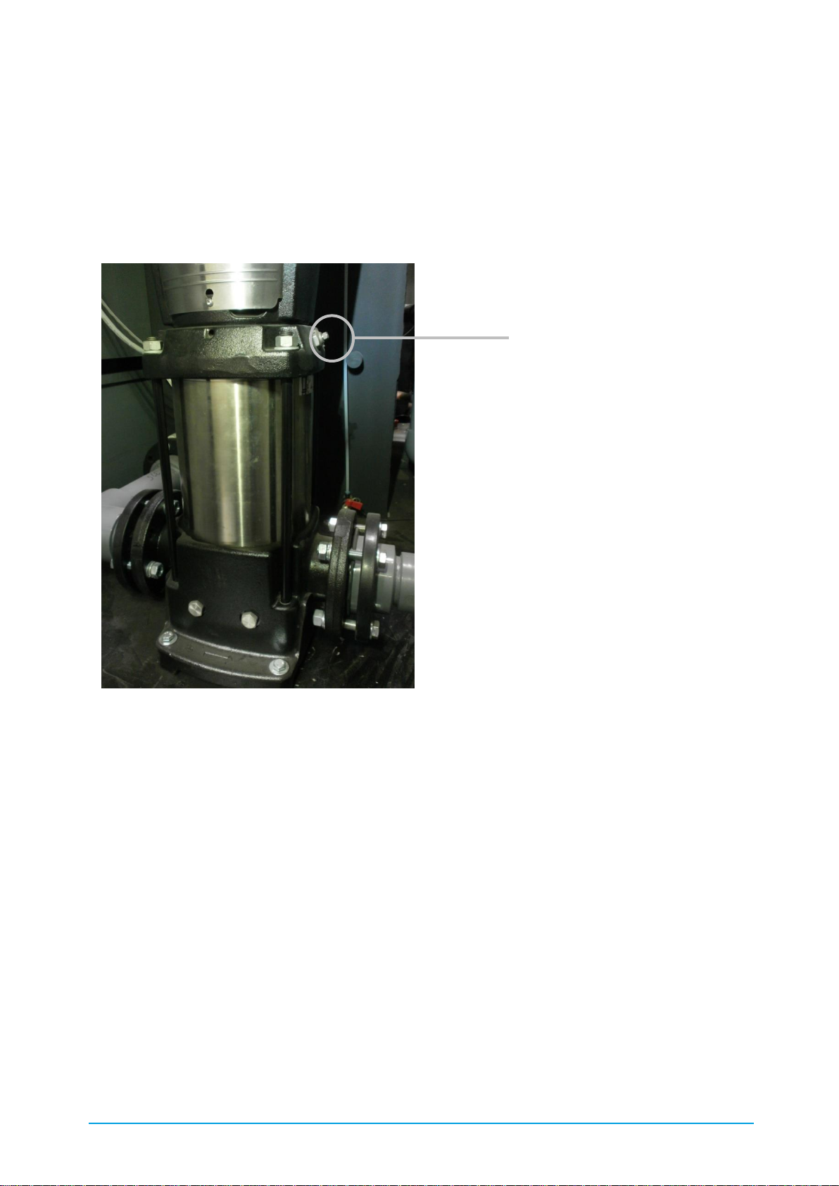
52 / 89 83000102.Ki
6.2.17. Venting
If your chiller contains a horizontal pump (standard for cBoxX 30 – cBoxX 100), the pump does
not have to be vented. If your chiller contains a vertical pump (standard for cBoxX 120 – cBoxX
200) the pump has to be vented. To do this, before switching on the pump the vent plug must be
opened and left open while the unit is running until all air has completely escaped from the pump
body (see Figure 17).
Figure 17: Position of the pump vent (vertical type)
If your chiller is equipped with an internal tank, further water circulation ensures that the residual
air in the overall system can escape into the atmosphere via the open tank.
For machines without a tank we recommend installing an automatic venting valve at the highest
point in the cold water circuit.
Pump venting
(here: open-ended spanner SW9)
Page 53
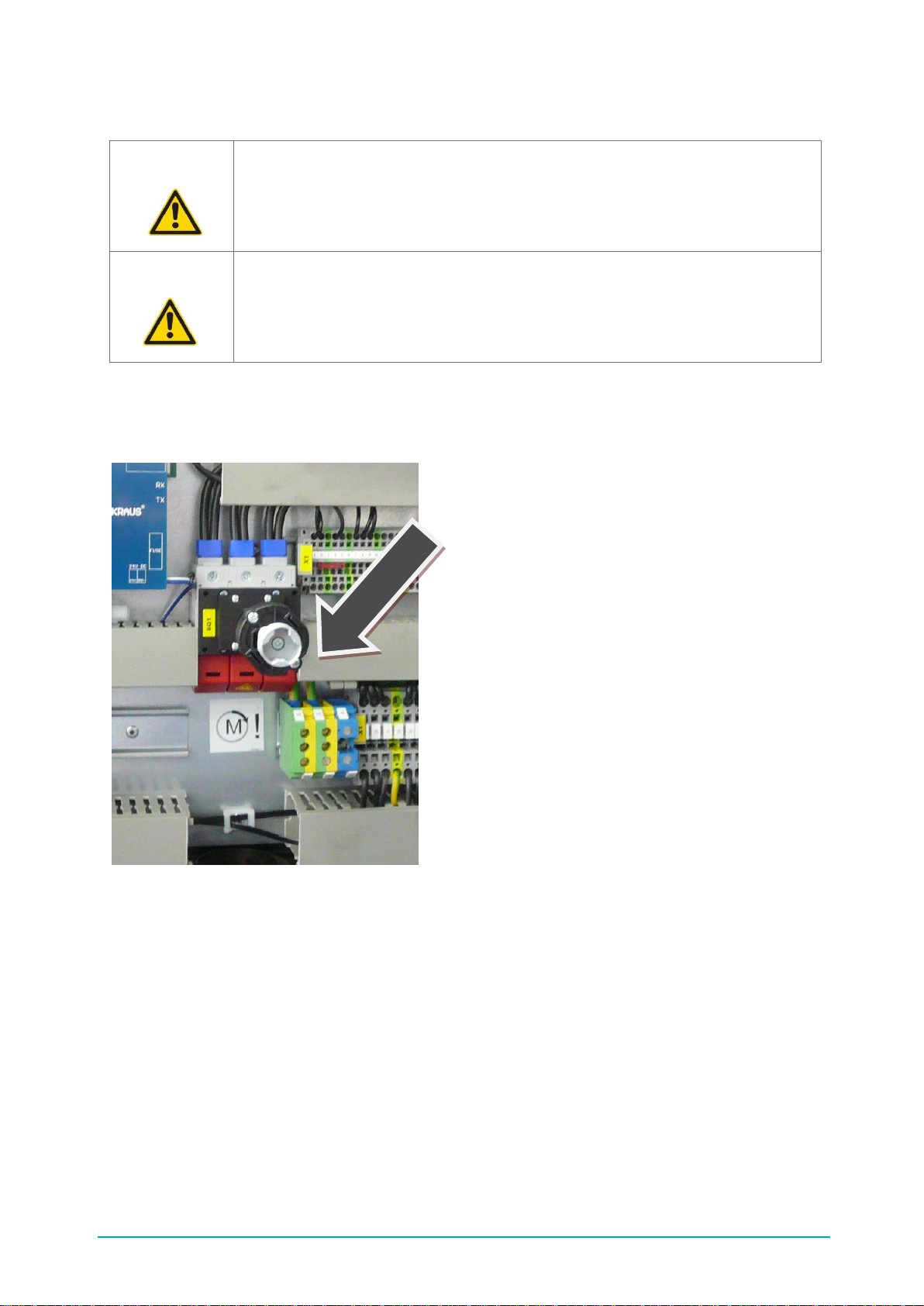
53 / 89 83000102.Ki
6.2.18. Electrical installation
The chiller is connected electrically to its main supply terminal in the control cabinet. (see Figure
18 Main supply). A circuit diagram is supplied with the unit.
Figure 18: Main supply
The dimensioning of the load cable and the fusing must be in accordance with the machine's
technical data and the local regulations of the power supply company.
The supply cable must be routed into the machine. Cut-outs are provided for this purpose in the
baseplate and in the compressor mount (cBoxX 30 – cBoxX 100). Feed the supply cable,
protected by rubber grommets, through these openings (see Figure 18 Main supply).
Never switch on the chiller immediately if the machine is moved from a cold into a warm room.
The condensing moisture can damage electronic components. For the initial startup or following a
lengthy period out of use all the electronic components must have become acclimatised.
ATTENTION! The electrical installation, testing and commissioning may only be
carried out by qualified personnel. Note and follow the local regulations.
ATTENTION! Do not switch on the chiller until the hydraulic installation is
completed and the machine has been filled as specified in Chapter 6.2.15.
Otherwise the machine could be damaged.
Page 54

54 / 89 83000102.Ki
Use an external control cable to set the chiller's release (see Chapter 8.3 External release); this
cable is laid parallel with the supply cable and is wired at the corresponding terminals in the
control cabinet (Refer to the circuit diagram included with the device).
If the electrical installation has been completed the phase sequence must be tested. This is done
by checking the rotational direction of the pump. This has a rotational direction arrow on it. If the
rotational direction does not match the arrow, the phase sequence can be corrected by swapping
two phases at the main supply.
7. Commissioning
Before commissioning the chiller the checklist must be used to check whether all the necessary
work in Chapter 6 Installation has been carried out properly.
The chiller must be installed for at least 12 hours at >+5 °C, so that the compressor oil can heat
up and the refrigerant can be liberated from the oil.
If your machine is equipped with oil sump heating and the machine has been completely
installed, it is permissible to switch on the machine at the main switch and to allow the
compressor to be preheated for at least 3 hours without enabling the cooling.
7.1. Installation checklist
▪ The device has been set up for at least 12 hours at >+5°C?
▪ Unit installed horizontal and stable?
▪ Any vibration damping and floor anchors installed?
▪ Spaces / clearances around the unit are adequate according to the requirements?
▪ Air intake side free from packaging materials, etc. ?
▪ Hydraulic connection OK?
▪ Cold water circuit filled in accordance with the specifications? Water quality OK?
▪ Whole system flushed? Dirt trap cleaned?
▪ Cross-sections adequately dimensioned?
▪ Electrical connection OK? Electrical power is available?
▪ External pumps OK? Rotational direction?
▪ Unit cover closed?
▪ Overall system OK and ready for commissioning/startup?
▪ Compressor "preheated" ?
▪ External enable OK?
After checking the above list you can continue with Chapter 8 Operation.
Page 55

55 / 89 83000102.Ki
8. Operation
The chiller is designed for fully automatic operation.
8.1. Switching on
First, switch on the machine at the main switch (component 5 in Figure 19: C6842 Display
elements and controls). The Start screen appears on the display.
8.2. Selecting the operating mode
In the Start screen you can choose between the following three operating modes:
▪ Standby operating mode
If you select " STANDBY " mode, all electrical components except the compressor heater
are switched off.
This operating mode is to be selected if the chiller was disconnected from the power
supply in ambient temperatures <5°C for longer than 6 h. In this case the compressors
must be preheated for 3 h, so that the refrigerant can escape from the oil.
▪ AUTO
With the selection of "AUTO" operating mode the machine is ready for use. The fully
automatic operation only starts in this mode if the external release has been installed
beforehand as described in Chapter 8.3 External release.
▪ ON
Fully automatic operation (without external release) starts with the selection of "ON"
mode.
8.3. External release
Wiring of the contacts for external release can be performed with an external control cable with a
potential-free switch. Please refer to Chapter 6.2.18 Electrical installation for information on the
external release. Fully automatic operation starts with this external release.
8.4. Control
The chiller's control consists of a control board and a control panel, which communicate with each
other via a BUS connection. The control board operates autonomously so that if the control panel
or communication fails, operation continues to be possible if no other fault prevents operation.
The program, target / setpoint values, parameters and times are stored in an Eprom in the
control and are therefore retained even in the event of a power failure. Therefore the control does
not require a buffer battery.
Page 56
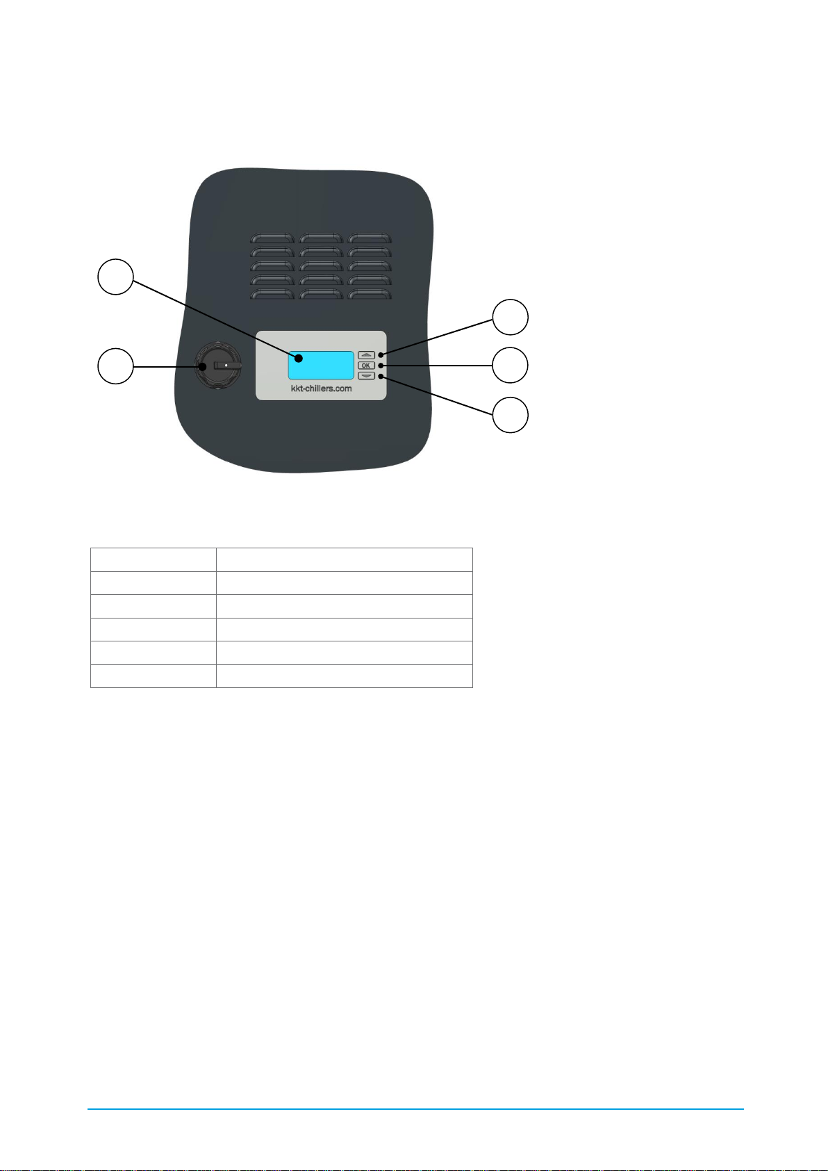
56 / 89 83000102.Ki
8.5. Control panel
The following Figure 19 shows the chiller's display elements and controls.
Figure 19: C6842 Display elements and controls
Table 15: Description of C6842
Number
Function
1
"UP" button
2
"OK" button
3
"DOWN" button
4
Display with plain text
5
Main switch
Use the "UP" and "DOWN" buttons to select the required menu item. The selected menu item is
displayed with inverse text. Press the "OK" button to return to or exit the selected menu. The data
is accepted at the end of the menu by selecting the box with the tick/checkmark. In the Start
screen the "right" arrow points towards the Main menu. The "left" arrow indicates return to the
previous menu.
The displays are divided into the three access levels
• Customer
• Factory
Detection occurs by means of a USB stick or day password. Only the information that exists or is
selected in the configuration is displayed.
1 2 3 4 5
Page 57
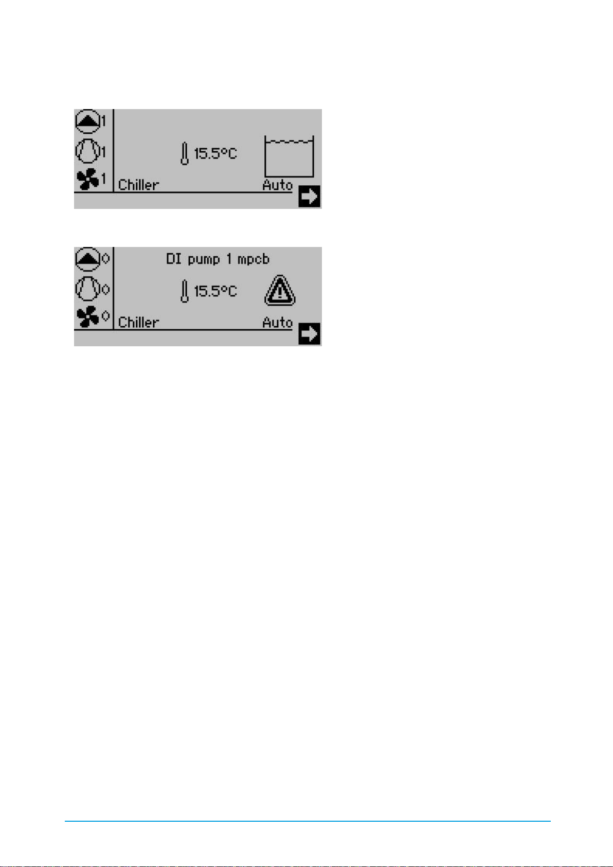
57 / 89 83000102.Ki
8.5.1. Start screen
Figure 20: Start screen with tank and without alarm
Figure 21: Start screen with alarm
The general operating state of the chiller is displayed on the Start screen:
• Active alarm
• Top left-hand side: Number of pumps running
• Left-hand middle: Number of compressors running
• Bottom left-hand side: Number of fans running
• Middle: Actual value of the cold water feed
• Right-hand side: Tank level (if tank installed)
If an alarm is active the alarm symbol is displayed
Press UP, DOWN and UP to switch to the selection fields, in which the Time - Date setting, the
menu access arrow as well as the operating status selection are located. There are three
switching commands:
• STANDBY: the chiller is always switched off
• AUTO: the chiller is switched on and off via the potential-free contact.
• ON: the chiller is always switched on
Page 58

58 / 89 83000102.Ki
8.5.2. Main menu
Figure 22: Main menu
From the Main menu you can move into the submenus or return to the Start screen.
8.5.3. Information
In the Information menu you can move into various submenus to obtain an overview of the state
of the chiller.
Figure 23: Information
In the Measured Value (Readings) menu you can call up the values of the analog inputs.
Figure 24: Measured Value menu
Page 59

59 / 89 83000102.Ki
In the Status menu the states of the digital inputs and outputs and several internal control states
can be called up.
Figure 25: Status menu
The alarms are listed in the Alarm menu. A detailed description is given in Chapter 8.5.5 Alarm
menu.
The operating hours counter gives information on the operating hours of the individual
components and cannot be reset.
Figure 26: Operating hours counter
The digital inputs shows the state at the terminals of the digital inputs.
Figure 27: Digital inputs
The digital outputs show the state of the output relays.
Figure 28: Digital outputs
Page 60

60 / 89 83000102.Ki
The analog inputs show the signal upstream of the analog digital converter. The value must be
between 0 and 4095. 0 means that no sensor is connected. 4095 means that the input is shortcircuited.
Figure 29: Analog inputs
The analog outputs show the signal upstream of the digital - analog converter. The value 10000
corresponds to an output voltage of 10 volts.
Figure 30: Analog outputs
8.5.4. Settings
All setpoint/target and parameter values and times are stored in the Settings menu.
Figure 31: Setting
8.5.5. Alarm menu
The alarm is acknowledged if the "OK" button is pressed for longer than eight seconds.(after five
seconds, the display switches back to the main menu)
• active: The alarm is still active. (e.g. DI MSS …) The motor protection switch has triggered.
• SH: The alarm is no longer queued. E.g. the motor protection switch has been unlocked on
the hardware side but has not yet been acknowledged at the control panel.
Page 61

61 / 89 83000102.Ki
Alarms that are preceded by the abbreviation DI refer directly to the digital input. All digital inputs
must be closed in a fault-free state. The abbreviation AI indicates a sensor error of an analog
input. The analog input must be checked for interruption and short circuit. Alarms without
abbreviations are formed internally in the control.
Figure 32: Alarm menu
8.6. Parameters
The parameters are divided into the three display and access levels:
• Customer, user
• Factory setting
A parameter can have a lower display level than access level. I.e. not all the parameters displayed
can be changed.
The specific parameter list for your application is enclosed with the unit.
Page 62

62 / 89 83000102.Ki
8.7. Controller description
8.7.1. Electronic level monitoring
Before switching on the chiller the electronic level monitoring starts up.
The level is monitored for three states:
• Tank min level STOP; the chiller switches off immediately.
• Tank min level warning; the chiller continues running but does not switch back on in the
event of a stoppage. The water feed solenoid valve (only with optional automatic water
top-up) is opened.
• Tank max level message; the cold water feed, water feed solenoid valve (only with
optional automatic water feed) is closed.
The ideal state is if the level is above the warning level and below the maximum level. In this case
no message appears.
If the chiller is switched on and the min level warning is reached the chiller remains switched on
so that any cooling process that has been started is not interrupted. If the chiller is switched off,
the chiller does not start, to ensure that no cooling process is initiated that may not be able to be
ended.
8.7.2. Switching the chiller On/off
The following conditions must be fulfilled for the chiller Standby state:
• The control has finished its initialisation routine,
• Release of at least one primary pump,
• Release of at least one condenser fan,
• Release of the cold water feed or return sensor,
• No exceeding of the cold water feed temperature,
• Release through tank level monitoring,
• Release through cold water pressure monitoring at the evaporator inlet.
A primary pump is released if:
• It is selected in the system configuration of the software,
• No motor protection switch faults are queued,
• No flow monitoring faults are queued,
• No minimum or maximum pump pressure faults are queued.
A condenser fan is released if:
• No motor protection switch faults are queued,
• No fault is queued at the digital fault input (e.g. control unit group fault).
From the Standby state, a software switch in the display can be used to switch the chiller between
Auto-On or Manual-On.. In Automatic mode the floating contact for the remote control must be
closed.
Page 63

63 / 89 83000102.Ki
When the system is switched on the primary pumps are switched on with a 3.5 s delay. After a
further 3.5 s the fan control is released.
When the primary pump is switched on a timing element starts for each pump, which activates
the monitoring of the minimum and maximum cold water pressure at the pump outlet. When the
pump is switched on a timing element also starts for release of the compressor's temperature
control. The compressor's temperature control is released when the time of a pump has expired.
This time is also used for activation of the flow monitoring.
The pressure and flow monitoring takes place with two timing elements:
• Delay at start; the pressure or the flow monitoring does not trigger an alarm.
• Delay during operation; in order to ignore short-term fluctuations in pressure or flow, the
alarm is delayed.
When the system is switched off the temperature control is locked immediately and therefore the
compressor is switched off. The pump continues running to prevent uncontrolled continued
evaporation.
8.7.3. Cold water flow temperature control
In the normal case the sensor in the tank (system with tank, with pump) is used to control the
cold water feed temperature. If this sensor fails, the control switches internally to the sensor in
the cold water return and the target value (setpoint value) is increased by a defined value.
A purely proportional controller is used, which generates an output signal from -100 % to +
100 %. The switching on and switching off points of the cooling levels are set within this range. If
the setpoint is changed the switching ratio between the compressors is retained, it is shifted
overall. If the proportional range is changed the switching ratio is also retained. The range is
extended or reduced.
Y
controller
Temperature
100 %
- 100 %
Heating =
electric
Y- cooling
Compressor 1 off
Set - heating
Hy-heating
Set - cooling
P-Band
cooling
Compressor 2 off
Compressor 3 off
Compressor 4 off
Compressor 4 on
Compressor 3 on
Compressor 2 on
Compressor 1 on
75 %
50 %
25 %
- 75 %
- 50 %
- 25 %
Figure 33: Cooling and heating sequence
Page 64

64 / 89 83000102.Ki
Different operating states reduce the number of cooling levels required by one cooling level:
• High pressure warning
• Low pressure warning
• Difference between high and low pressure is too large.
8.7.4. Compressor control
The control is defined for a refrigeration circuit with a maximum of four compressors. The number
of compressors is selected by means of coding resistance. The number of compressors is
determined once when the control is restarted (switching on of the operating voltage) and is
compared with the number of the last restart. If these are not the same the "Coding resistance
changed" alarm is generated. When the alarm is acknowledged the new number of compressors
is stored in the E-EPROM and the factory setting is accepted as the new number of compressors.
The compressors are requested depending on the controller output signal. The compressor with
the least number of operating hours switches on first. If no more refrigerating capacity is required
the compressor that switched on first also switches off first. The compressors are switched on
with a time delay (comment: only applies if several compressors exist)
In the event of a fault in a compressor (motor protection switch) a fault changeover is activated.
The high pressure is monitored on the hardware side by means of the high-pressure limiter. If it is
triggered all compressors switch off immediately. In addition, the high pressure is controlled by
means of a pressure transmitter. This also switches off the compressors if the setpoint is
exceeded, but releases them again if the value falls below the release value. Before switching off
the, high-pressure transmitter signals a warning.
Low pressure is also monitored by pressure transmitters. If the value falls below the setpoint the
compressors switch off. If the switch-off value is exceeded by the hysteresis, the compressors are
released again. The triggering of the alarm is delayed by two timing elements. The first timing
element is started with the request for the compressor. If no intake pressure has built up by the
time the time expires the low-pressure fault alarm is triggered. After the start time has expired the
low pressure may exceed the switch-off value for a short time. If this occurs more than three
times within an hour the compressors are blocked. Before a low-pressure fault is triggered a lowpressure warning is signalled.
8.7.5. Fan speed control
Due to the continuous adjustment in the number of fans, the condensing pressure is kept
constant depending on the ambient temperature by means of a PI controller. As the condensing
pressure at the moment in which the compressor is switched on rises very fast, the PI controller is
superimposed by a P controller with limiting setpoint. This only intervenes if the PI controller is too
slow.
Page 65

65 / 89 83000102.Ki
8.7.6. Electronic expansion valve control
An electronic expansion valve with PI controller is used to keep the overheating constant. To
prevent the maximum operating pressure (MOP) from being exceeded, a P controller is used,
which counteracts when the MOP is approached and limits opening of the electronic expansion
valve.
8.7.7. Temperature limit monitoring
The temperature of the cold water feed is monitored for a minimum and maximum limit value if
the chiller is switched on (pump is running). If the limit value is exceeded or the minimum is not
reached, an alarm is triggered with time delay, which switches off the chiller.
8.7.8. Group fault alarm
A group fault alarm is triggered if an alarm occurs. All alarms are included in the group fault, but
not the warnings. The group fault signalling relay has a floating changeover contact and is
energised in fault-free operation, in order to ensure wire break monitoring.
8.8. Operating modes
It is possible to choose between two operating modes:
8.8.1. ECO mode
The default setting of the Compact-Line provides for operation in ECO mode ("Run" parameter is
set to "0"). As a result, the increase in fan speed reduces the condensing pressure to the
minimum necessary value in the respective operating point – the electrical power consumption of
the overall system is limited to a minimum.
8.8.2. Comfort mode
In case of strict sound emission requirements the fan speed can be reduced to the minimum
necessary value in the respective operating point and sound power level limited to a minimum. To
do this the "Run" parameter must be set to "1". As a result of the lower air flow rate a reduced
output of around 3% is to be expected.
The optimised parameter list for your application is enclosed with the unit.
Page 66

66 / 89 83000102.Ki
9. Cleaning
9.1. Air filter mat
To maintain high performance the optional air filter mat (3.19 Air filter mat) must be checked for
contamination at least once a month. The correct air filter mats can be ordered at any time as an
original spare part – please contact our KKT chillers Service Team (Table 1 Contact details).
9.2. Condenser
To maintain high performance the microchannel heat exchanger must be cleaned if there is any
visible contamination, but at least annually. To do this, disconnect the unit from the power supply
and remove the service panels and the condenser protective grille (panels 3 and 5, see Chapter
1.3 Elements). First of all, remove coarse dirt particles from the outside using a standard vacuum
cleaner. Then flush the microchannel heat exchanger carefully, in the opposite direction to the air
flow, from inside with warm tap water. Then clean with a wet vacuum cleaner until the surface is
dry again. For versions with water cooled condensers see complete cleaning of the cold water
circuit.
9.3. Water filter
To ensure the required water quality and the required water circulation quantity, the optional
water filter (3.22 Filter assembly group coolant ) must be checked for contamination at least
once a month. The correct filter unit can be ordered at any time as an original spare part – please
contact our KKT chillers Service Team (Table 1 Contact details).
9.4. Complete cleaning of the cold water circuit
Due to the complexity and diversity of the possible external materials, we recommend that the
complete cleaning of the cold water circuit only be carried out by qualified personnel – please
contact our KKT chillers Service Team (Table 1 Contact details).
Page 67

67 / 89 83000102.Ki
10. Service
All service work may only be carried out by properly trained, competent personnel.
10.1. Maintenance
Reliable operation and a long service life for the entire system can be guaranteed by proper
maintenance.
The purpose of the maintenance is:
• to ensure that the machine operates reliably and without unexpected failures
• to plan further service work in order to minimise downtimes
An overview of the maintenance intervals as recommended by the VDMA is given in Appendix II. In
addition, the national regulations of the respective installation site must be followed.
Please note that the points listed represent the minimum maintenance required. By increased
monitoring, system reliability can be rnhanced. Please contact our service department at any time
about maintenance quotations / service agreements.
10.2. Fault correction
Troubleshooting and fault correction instructions are given in Appendix 0.
Our technical customer service can be reached around the clock and will assist you with all
service matters (maintenance, repairs, spare parts, etc.):
Europe Service Team
T +49 9228 9977 7190
E service@kkt-chillers.com
W www.kkt-chillers.com
USA Service Team
TF +1 866 517 6867
E support@kkt-chillersusa.com
W www.kkt-chillersusa.com
10.3. Spare parts
To ensure that the performance of your chiller is not impaired, we recommend that you only use
original spare parts purchased from KKT chillers. In this way you ensure the reliability and quality
of the machine. If you have any questions about spare parts, please contact our KKT chillers
Service Team (Table 1 Contact details).
Page 68
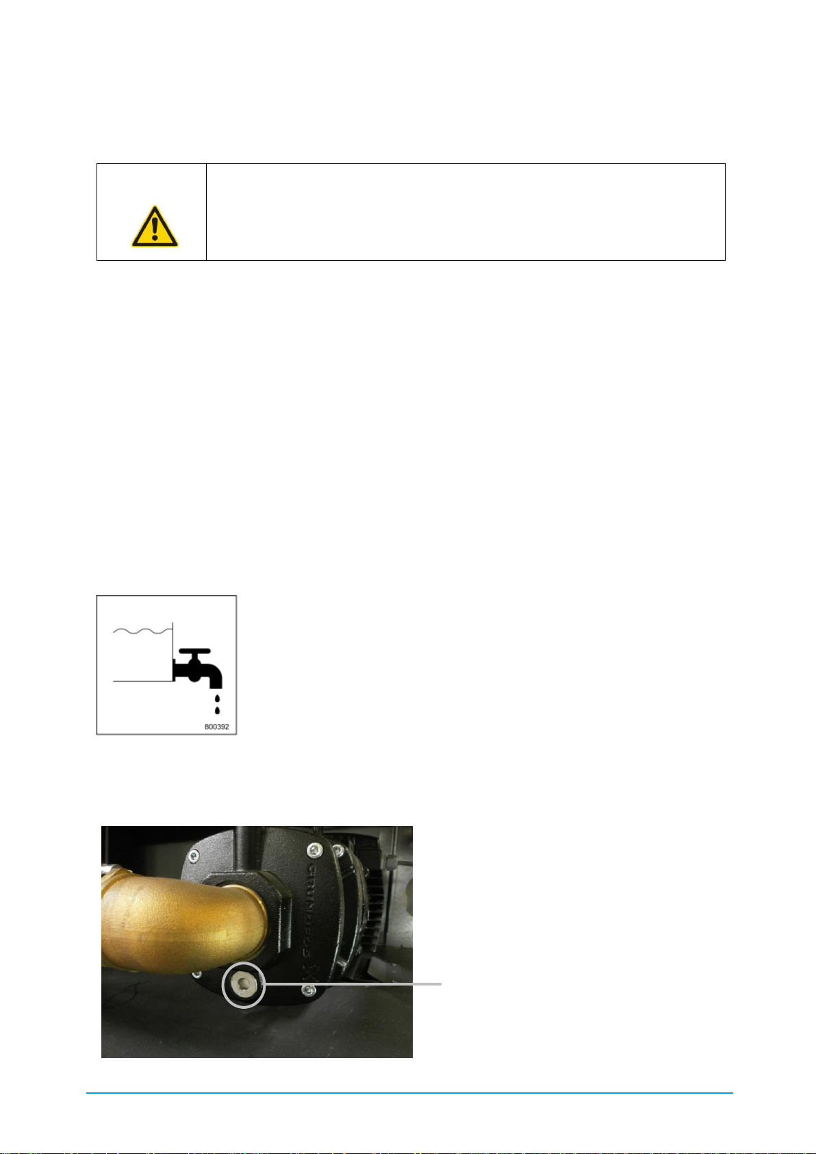
68 / 89 83000102.Ki
11. Taking out of service
For safety-relevant instructions regarding possible residual energy, please refer to Chapter 4.3
Residual energy.
11.1. Draining
If the system is filled and there is a risk of frost, suitable measures must be taken to protect the
liquid from frost. The complete cold water circuit must be fully drained before any lengthy
stoppage of the unit. Do this as follows:
1. Drain the tank via the drain cock provided
(when doing so, close the shut-off valve leading the level sensor)
2. Drain the evaporator via the drain cock provided
3. Drain the pump using the drain plug provided
The drain cock is marked on the unit by the symbol in Figure 34.
Figure 34: Labelling of the drain cock
The position of the drain plug is shown in Figure 35.
ATTENTION! Decommissioning must only be carried out by professional and
qualified technicians.
They must also be familiar with the local regulations.
Drain plug
(Allen key 10 mm)
Page 69

69 / 89 83000102.Ki
Figure 35: Position of the pump drainage (horizontal type)
To prevent frost damage the cold water circuit must then be flushed with a mixture of water and
40 % by vol Antifrogen-N (or equivalent).
12. Recycling
All parts (e.g. refrigerant, oil, glycol, metal, electronics, battery etc.) must be recycled, reused or
disposed of. Please note and follow all local and national regulations and if necessary contact
your local waste management agency.
A specialised disposal company must be contracted to dispose of these wastes. They issue a
proof of disposal which must be archived. The chiller can be returned to KKT chillers for disposal.
Please contact our KKT chillers Service Team for details (Table 1 Contact details).
13. Products, solutions and services
Apart from the Compact-Line, KKT chillers also offers other products, solutions and services
which are not described in this document. For more information, visit our homepage
http://www.kkt-chillers.com or contact your KKT chillers contact (Table 1: Contact details)– we
look forward to hearing from you!
ATTENTION! Dismantling must be carried out by professional and qualified
technicians.
Water and refrigerant pipes are pressurised!
They must also be familiar with the local regulations.
Page 70

70 / 89 83000102.Ki
14. Lists
14.1. List of illustrations
Figure 1: C6848 refrigeration diagram ............................................................................................... 13
Figure 2: Demounting the side panel of the switch cabinet .............................................................. 16
Figure 3: C6856 thermostatic pump start with overflow valve (recommended installation) .......... 22
Figure 4: C6863 overflow valve for standby mode ............................................................................ 22
Figure 5: Top-up connection ................................................................................................................ 23
Figure 6: Machine base (foot) – outside view .................................................................................... 25
Figure 7: Machine base (foot) - mounting on the baseplate ............................................................. 25
Figure 8: Position of the high-pressure limiter (PZH) ......................................................................... 33
Figure 9: Airborne sound emissions .................................................................................................... 36
Figure 10: C6845-0 centre of gravity cBoxX 30 - 60 ......................................................................... 42
Figure 11: C6846-0 centre of gravity cBoxX 70 – 100 ...................................................................... 42
Figure 12: C6846-0 centre of gravity cBoxX 120 – 160 ................................................................... 42
Figure 13: C6846-0 centre of gravity cBoxX 180 – 200 ................................................................... 42
Figure 14: C6841-0 crane transport cBoxX 30 - 100 ........................................................................ 43
Figure 15: Exhaust air duct cBoxX 30-200 ......................................................................................... 47
Figure 16: Filling and feed connection ............................................................................................... 51
Figure 17: Position of the pump vent (vertical type) .......................................................................... 52
Figure 18: Main supply......................................................................................................................... 53
Figure 19: C6842 Display elements and controls ............................................................................. 56
Figure 20: Start screen without alarm ................................................................................................ 57
Figure 21: Start screen with alarm ...................................................................................................... 57
Figure 22: Main menu .......................................................................................................................... 58
Figure 23: Information ......................................................................................................................... 58
Figure 24: Measured Value menu ....................................................................................................... 58
Figure 25: Status menu ....................................................................................................................... 59
Figure 26: Operating hours counter .................................................................................................... 59
Figure 27: Digital inputs ....................................................................................................................... 59
Figure 28: Digital outputs .................................................................................................................... 59
Figure 29: Analog inputs ...................................................................................................................... 60
Figure 30: Analog outputs .................................................................................................................... 60
Figure 31: Setting ................................................................................................................................. 60
Figure 32: Alarm menu ........................................................................................................................ 61
Figure 33: Cooling and heating sequence .......................................................................................... 63
Figure 34: Labelling of the drain cock ................................................................................................ 68
Figure 35: Position of the pump drainage (horizontal type) .............................................................. 69
14.2. List of tables
Table 1: Contact details ......................................................................................................................... 2
Table 2: Safety instructions ................................................................................................................... 8
Page 71

71 / 89 83000102.Ki
Table 3: Technical data .......................................................................................................................... 9
Table 4: Explanation of terms .............................................................................................................. 12
Table 5: Materials used - standard version ........................................................................................ 17
Table 6: Materials used for the non-ferrous metal-free version ........................................................ 18
Table 7: Water quality .......................................................................................................................... 19
Table 8: AFN and AFL mix ratios (or equivalent) ................................................................................ 20
Table 9: Definition of the safety symbols ............................................................................................ 30
Table 10: Hazard warnings .................................................................................................................. 31
Table 11: Personal protective equipment for servicing work ............................................................ 35
Table 12: Description of figure C6841-0 ............................................................................................ 43
Table 13: Materials in the packaging .................................................................................................. 44
Table 14: Minimum volume of the installation room with regard to maximum refrigerant
concentration in case of a leakage if installed indoors ..................................................................... 46
Table 15: Description of C6842 .......................................................................................................... 56
Page 72
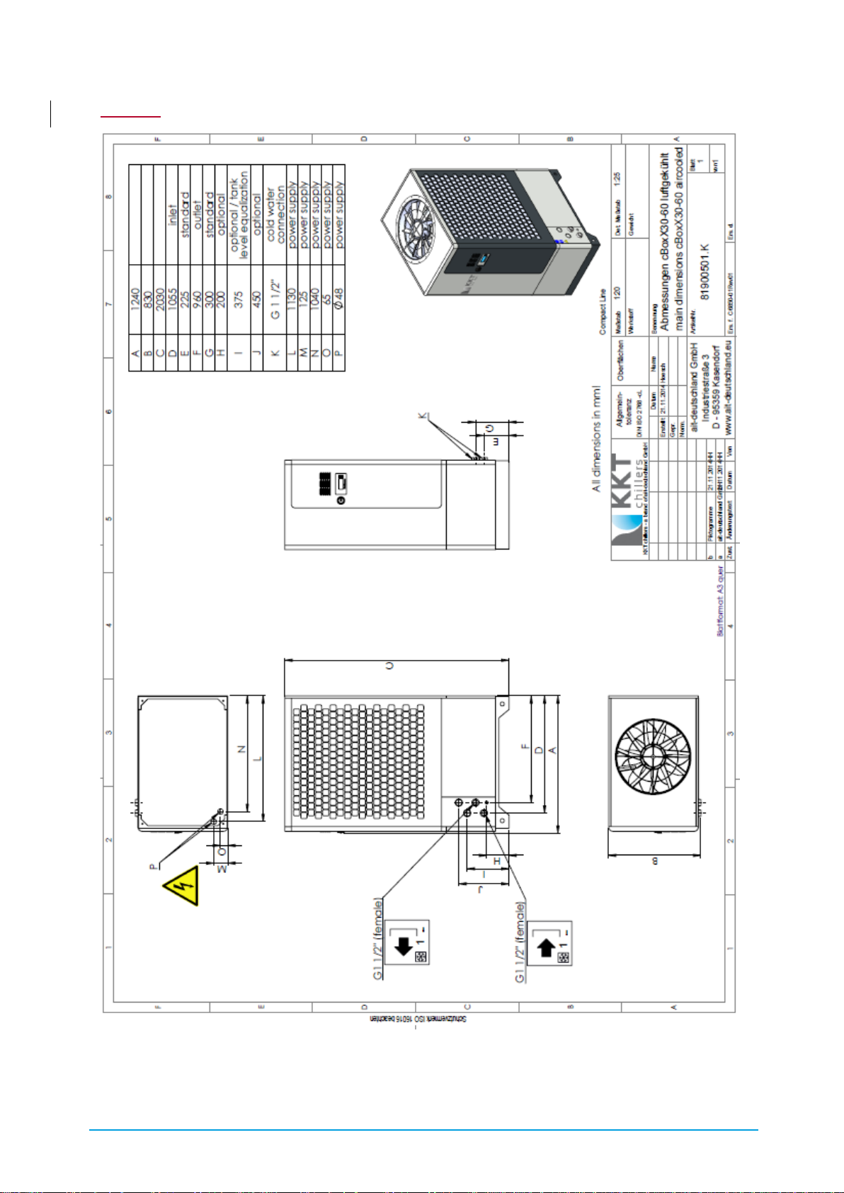
72 / 89 83000102.Ki
I. Main dimensions
Page 73
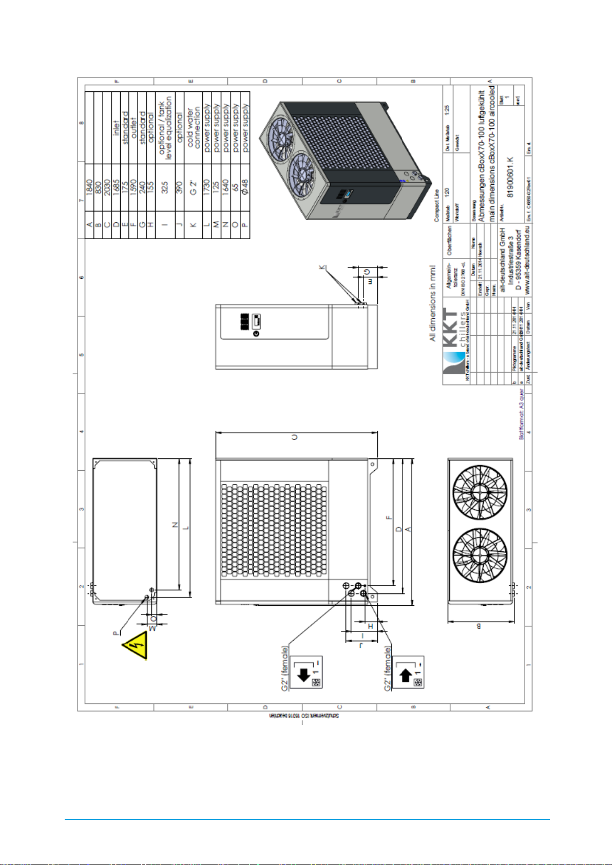
73 / 89 83000102.Ki
Page 74

74 / 89 83000102.Ki
Page 75
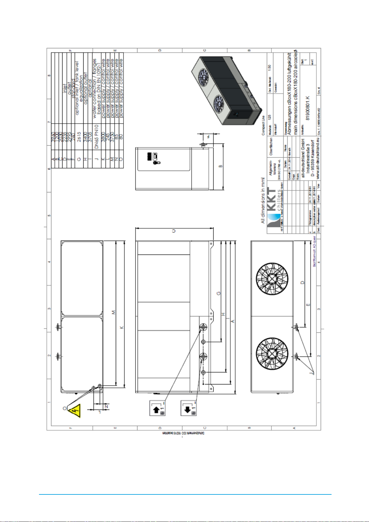
75 / 89 83000102.Ki
Page 76

76 / 89 83000102.Ki
II. Installation instructions
Page 77

77 / 89 83000102.Ki
Page 78

78 / 89 83000102.Ki
Page 79

79 / 89 83000102.Ki
Page 80

80 / 89 83000102.Ki
I.III. Troubleshooting
Error
code
cBoxX display
Message description
Cause of the message
Troubleshooting
111
HP warning
Condensation pressure has
exceeded the warning limit
Condensation pressure
threatens to rise up to the
high-pressure stop limit;
one compressor is
switched off (if two or
more compressors are
present)
Clean the condenser
and filter. Check the
function of the fan.
Check the cooling
water circuit. Install the
cover panels.
121
LP warning
Evaporation pressure has
fallen below the warning
limit
Evaporation pressure
threatens to fall to the lowpressure stop limit; one
compressor is switched off
(if two or more
compressors are present)
Check liquid flow.
Check the function of
the expansion valve.
Check the refrigerant
level.
151
HP STOP
Condensation pressure is
outside the allowable range.
Unable to remove the
waste heat of the
refrigeration circuit.
Clean the condenser
and filter. Check the
function of the fan.
Check the cooling
water circuit. Install the
cover panels. Press the
Reset button and
acknowledge at the
display.
161
LP STOP
Low pressure sensor has
tripped. Pressure has fallen
below the minimum
allowable pressure on the
intake side of the
compressor (low pressure
side).
Liquid flow through the
evaporator is too low.
Refrigerant loss. Faulty
function of the expansion
valve. Faulty function of
the LP sensor.
Check liquid flow.
Check the function of
the expansion valve.
Check the refrigerant
level.
162
LP STOP 3times
Low pressure sensor has
tripped. Pressure has fallen
below the minimum
allowable pressure on the
intake side of the
compressor (low pressure
side).
Liquid flow through the
evaporator is too low.
Refrigerant loss. Faulty
function of the expansion
valve. Faulty function of
the LP sensor.
Check liquid flow.
Check the function of
the expansion valve.
Check the refrigerant
level.
171
Superheating
The superheating value has
fallen below the minimum
limit. vBoxX min; cBoxX min
& max
Superheating too low
Reset takes place
automatically
301
Outlet temp. max warn.
Outlet temperature of the
liquid circuit is approaching
the upper limit
Thermal overload,
No cold production
(refrigeration).
Check refrigerating
capacity, check the
function of the
refrigeration circuit
312
Min tank level warning
Level in the tank is
approaching the minimum
limit.
Level in the tank is too
low, level sensor in the
tank is defective.
Fill the tank, check the
function of the sensor
in the tank
313
SV timelimit tank refill
The solenoid valve of the
tank refill does not close
within the specified time
The freshwater supply is
interrupted.
Check the function of
the solenoid valve for
freshwater supply,
open shut-off valves
integrated in the supply
pipe. Check supply
pipe for leakage
Page 81

81 / 89 83000102.Ki
321
CW press.evap. warn.
The liquid pressure at the
evaporator is approaching
the minimum or maximum
limit
External gate valve closed,
Filter dirty,
Air in the system.
Open the external gate
valve,
Clean the filter,
Vent the system.
325
Press exp.tank min warning
Pump intake pressure is
below the set setpoint
Expansion vessel is
defective
Quantity of water in the
closed pipe system is too
small
Top-up water
326
327
Pumppress.1min warn.
Pumppress.ka warn.
The pump's pressure is
approaching the minimum
limit
Flow rate too high, chiller
resistance too low,
air in the system
Reduce flow rate,
increase chiller
resistance, vent the
system
331
Conductivity max STOP
Conductivity is approaching
the maximum limit
The current conductivity is
too high in relation to the
specified area of use
Check the setpoint
default. If installed:
Check DI cartridge,
check flow through DI
cartridge.
332
Conductivity max. warn.
Conductivity is approaching
the maximum limit
The current conductivity is
too high in relation to the
specified area of use
Check the setpoint
default. If installed:
Check DI cartridge,
check flow through DI
cartridge.
333
EV demineralis. timelimit
The solenoid valve of the DI
circuit does not close within
the specified time
The lower conductivity
limit is not reached.
Check the limit default.
Check the conductivity.
Check flow through the
DI cartridge.
351
Outlet temp. Max STOP
Maximum outlet
temperature exceeded.
Thermal overload,
No cold production
(refrigeration).
Check refrigerating
capacity, check the
function of the
refrigeration circuit
352
Outlet temp. Min STOP
Outlet temperature is below
the minimum.
Tank heating function
disrupted, setpoint set too
low, ambient temperature
too low
Check the function of
the tank heating, check
the setpoint, increase
the ambient
temperature
361
Min tank level STOP
Level in tank is below the
minimum.
Level in the tank is too
low, level sensor dirty,
defective
Fill tank, check the
function of the tank
sensor
371
CW press. evap. STOP
Cold water pressure at the
evaporator is too low.
External gate valve closed,
Filter dirty,
Air in the system.
Open external gate
valve, clean filter, vent
the system.
372
CW press. evap. STOP
Cold water pressure at the
evaporator is too low.
External gate valve closed,
Filter dirty,
Air in the system.
Open external gate
valve, clean filter, vent
the system.
378
Press exp.tank max STOP
Intake pressure of the pump
is above the set setpoint
Expansion vessel is
defective
Quantity of water in the
closed pipe system is too
large
Drain off water
379
Press exp.tank min STOP
Pump intake pressure is
below the set setpoint
Expansion vessel is
defective
Quantity of water in the
closed pipe system is too
small
Top-up water
381
385
Pumppress.1 max STOP
Pumppress.2 max STOP
Liquid outlet pressure too
high
External gate valve closed,
Filter dirty
Open external gate
valve, clean filter,
check overflow valve
setting
Page 82

82 / 89 83000102.Ki
382
386
Pumppress.1 min STOP
Pumppress.2 min STOP
Liquid outlet pressure too
low
Flow rate too high, chiller
resistance too low,
air in the system
Reduce flow rate,
increase chiller
resistance, vent the
system
501
AI inlet temp. (VP)
Output value of the sensor
is incorrect
Sensor short-circuit or
sensor break
Use the characteristic
curve to check the
electrical connection of
the sensor
502
AI outlet temp.
Output value of the sensor
is incorrect
Sensor short-circuit or
sensor break
Use the characteristic
curve to check the
electrical connection of
the sensor
503
AI outlet temp. 2
Output value of the sensor
is incorrect
Sensor short-circuit or
sensor break
Use the characteristic
curve to check the
electrical connection of
the sensor
504
AI temp.system return
Output value of the sensor
is incorrect
Sensor short-circuit or
sensor break
Use the characteristic
curve to check the
electrical connection of
the sensor
505
AI ambient temp.
Output value of the sensor
is incorrect
Sensor short-circuit or
sensor break
Use the characteristic
curve to check the
electrical connection of
the sensor
506
AI freecooler temp inlet
Output value of the sensor
is incorrect
Sensor short-circuit or
sensor break
Use the characteristic
curve to check the
electrical connection of
the sensor
511
AI CW press. evap.
Output value of the sensor
is incorrect
Sensor short-circuit or
sensor break
Use the characteristic
curve to check the
electrical connection of
the sensor
512
AI press exp.tank
Output value of the sensor
is incorrect
Sensor short-circuit or
sensor break
Use the characteristic
curve to check the
electrical connection of
the sensor
513
AI pump press. 1
Output value of the sensor
is incorrect
Sensor short-circuit or
sensor break
Use the characteristic
curve to check the
electrical connection of
the sensor
514
AI pump press. 2
Output value of the sensor
is incorrect
Sensor short-circuit or
sensor break
Use the characteristic
curve to check the
electrical connection of
the sensor
515
AI tank pressure
Output value of the sensor
is incorrect
Sensor short-circuit or
sensor break
Use the characteristic
curve to check the
electrical connection of
the sensor
521
AI high pressure
Output value of the sensor
is incorrect
Sensor short-circuit or
sensor break
Use the characteristic
curve to check the
electrical connection of
the sensor
522
AI low pressure
Output value of the sensor
is incorrect
Sensor short-circuit or
sensor break
Use the characteristic
curve to check the
electrical connection of
the sensor
523
AI suction gas temp.
Output value of the sensor
is incorrect
Sensor short-circuit or
sensor break
Use the characteristic
curve to check the
electrical connection of
the sensor
Page 83

83 / 89 83000102.Ki
524
AI hot gas temp.
Output value of the sensor
is incorrect
Sensor short-circuit or
sensor break
Use the characteristic
curve to check the
electrical connection of
the sensor
525
AI liquid temp.
Output value of the sensor
is incorrect
Sensor short-circuit or
sensor break
Use the characteristic
curve to check the
electrical connection of
the sensor
526
AI cool. water temp.
Output value of the sensor
is incorrect
Sensor short-circuit or
sensor break
Use the characteristic
curve to check the
electrical connection of
the sensor
531
AI conductivity
Output value of the sensor
is incorrect
Sensor short-circuit or
sensor break
Use the characteristic
curve to check the
electrical connection of
the sensor
534
AI air flow
Output value of the sensor
is incorrect
Sensor short-circuit or
sensor break
Use the characteristic
curve to check the
electrical connection of
the sensor
541
AI gas concentration
Output value of the
separation stage is incorrect
Connection to the
separation stage is
interrupted, separation
stage defective, incorrectly
configured
Check the connection
to the separation
stage, check the output
signal of the separation
stage
591
AI coding resistor
Measured resistance is
incorrect
Resistor is loose or
defective or resistance
value is incorrect
Test the electrical
resistance
592
Coding changed
Coding error
The resistor has measured
different coding (number
of compressors) since the
last switching on
Coding resistor
defective, not
connected, check the
contact
601
DI emergency stop
Emergency shutdown has
tripped
External contact
Check the external
conditions
602
DI 3-phases
Phase monitoring has
tripped
Error in relation to phase
sequence, phase failure,
undervoltage and
asymmetry
Check feed
611
615
619
DI mpcb Pump 1
DI mpcb Pump 2
DI mpcb pump freec.
Motor protection switch has
tripped
Motor current above the
allowable range,
Motor is running in two
phases only, rotational
direction,
poor contact at terminal
connections,
interturn short-circuit,
earth fault, rotor blocked.
Check the motor power
consumption, check
the operating point,
check the electrical
connection of the
components
612
616
DI pump 1 error
DI Pump 2 error
Internal monitoring of the
pump tripped
Motor is running in two
phases only, rotational
direction,
poor contact at terminal
connections,
interturn short-circuit,
earth fault, rotor blocked.
Check the motor power
consumption, check
the electrical
connection of the
components, check for
mechanical blocking,
613
617
Pump 1 flow start
Pump 2 flow start
Flow switch did not switch
through after the pump
start-up phase
Flow too low
Check flow, check shutoff valves, check pump,
check the setting of the
reed contact at the
flow monitor
Page 84

84 / 89 83000102.Ki
614
618
Pump 1 flow running
Pump 2 flow running
Flow switch did not switch
through during the pump
operating phase
Flow too low
Check flow, check shutoff valves, check the
setting of the reed
contact at the flow
monitor
621
622
623
624
DI mpcb compressor 1
DI mpcb compressor 2
DI mpcb compressor 3
DI mpcb compressor 4
Motor protection switch has
tripped
Motor current above the
allowable range,
Motor is running in two
phases only, rotational
direction,
poor contact at terminal
connections,
interturn short-circuit,
earth fault, rotor blocked.
Check the motor power
consumption, check
the operating point,
check the electrical
connection of the
components
627
DI HP delimiter
High-pressure limiter has
tripped.
Unable to remove the
waste heat of the
refrigeration circuit.
Clean the condenser
and filter. Check the
function of the fan.
Check the cooling
water circuit. Install the
cover panels. Press the
Reset button and
acknowledge at the
display.
631
633
635
DI mpcb fan 1
DI mpcb fan 2
DI mpcb freecool.fan
Motor protection switch has
tripped
Motor current above the
allowable range,
Motor is running in two
phases only, rotational
direction,
poor contact at terminal
connections,
interturn short-circuit,
earth fault, rotor blocked.
Check the motor power
consumption,
Check the operating
point, check the
electrical connection of
the components
632
634
636
DI fan 1 error
DI fan 2 error
DI fan error freecooler
Internal monitoring of the
fan has tripped.
Motor is running in two
phases only, rotational
direction,
poor contact at terminal
connections,
interturn short-circuit,
earth fault, rotor blocked.
Check the motor power
consumption, check
the electrical
connection of the
components, check for
mechanical blocking,
641
DI mpcb tank heating
Circuit breaker has tripped.
Current above the
allowable range,
poor contact at terminal
connections due to dirt or
corrosion,
short-circuit between the
heating elements, earth
fault.
Check the electrical
connection to the
components, test for
short to earth
642
DI STP tank heating
Safety temperature limiter
of the tank heating has
tripped
Tank temperature too
high,
no water in the tank,
tripping point of the safety
temperature limiter (STP)
set incorrectly.
Check the tank
temperature, check the
level, check the
tripping point of the
STP
Page 85
85 / 89 83000102.Ki
II.IV. Maintenance intervals in accordance with the VDMA
Explanation
Annual
Six-
monthly
As
required
Remark
Compressor
1
Optical check for dirt, damage and corrosion
x x
2
Check fixing, check running noises
x
3
Measure the intake pressure
x
4
Measure the suction gas temperature upstream
of the compressor
x
5
Measure the compression end temperature at
the discharge port
x
6
Check the oil level
x
7
Check the acid content of the oil (acid test)
x
8
Oil change
x
9
Check that the crankcase heater is working
x
10
Check that the output control is working
x
11
Check the refrigerant side for leaks
x
12
Check high/low pressure switching equipment
x
Air-cooled condenser
20
Optical check for dirt, damage and corrosion
x x
21
Measure the condensing temperature
x
22
Measure the refrigerant side supercooling
temperature at the condenser outlet
x
23
Measure the medium temperature at condenser
inlet and outlet
x
24
Check that the condensation pressure control is
functioning properly
x
25
Check the refrigerant side for leaks
x
Evaporator
30
Optical check for dirt, damage and corrosion
x
31
Measure refrigerant overheating temperature
x
32
Measure the medium temperature at the
evaporator inlet and outlet
x
33
Measure the anti-freeze temperature (freezing
point) of the heat transfer media
x
34
Check the water and refrigerant side for leaks
x
Page 86
86 / 89 83000102.Ki
Explanation
Annual
Six-
monthly
as
required
Remark
Parts in the refrigeration circuit/water circuit
40
Optical check for dirt, damage and corrosion
x x
41
Check insulation for damage
x
42
Check filter dryer for blockage
x
43
Replace filter dryer
X
If com-
ponents
in the
refrig-
eration
circuit
are
replaced
45
Check all pipes carrying refrigerant for corrosion
and damage
x
Fans
50
Optical check for dirt, damage and corrosion
x x
51
Check fixings and bearings
x
52
Check flexible connection for tightness
(electrical connection)
x
Pump and piping
60
Optical check for dirt, damage and corrosion
x
61
Check fixing parts and bearings
x
62
Check the safety function of the safety switching
devices
x
63
Check pump/mechanical seal for leaks
x x
Water filters
70
Optical check for dirt, damage and corrosion
x x
71
Clean filters
x x
72
Check filters for damage
x
Page 87
87 / 89 83000102.Ki
No.:
Explanation
Annual
Six-
monthly
as
required
Remark
Tank / water tank
80
Optical check for dirt, damage and corrosion
x
81
Check fixing
x
82
Check level
x
Control cabinet
90
Optical check for dirt, damage and corrosion
x x
91
Check fixing
x
92
Check all threaded connections
x
93
Check all indicator lights and error messages
x
94
Check the temperature and pressure sensors
are functioning properly
x
95
Check the function of the motor protection
switches
x
96
Check 24 VDC and supply voltage
x x
97
Check control cabinet heater
x
99
Check control cabinet filter and if necessary
replace/clean
x
Documents and labelling
110
All documents such as operating instructions,
diagrams, circuit plans, system log are present
x x
111
Rating plate and labels are clearly legible
x x
Battery - time/date
120
Battery x Every 5
years
Leakage control of the refrigeration circuit in
accordance with (EC) 517/2014
x
Page 88
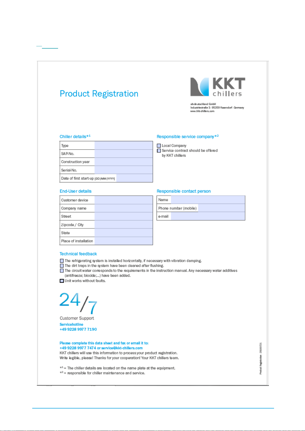
88 / 89 83000102.Ki
III.V. Product Registration
PDF download: http://www.kkt-chillers.com/en/downloads/product-registration/
Page 89
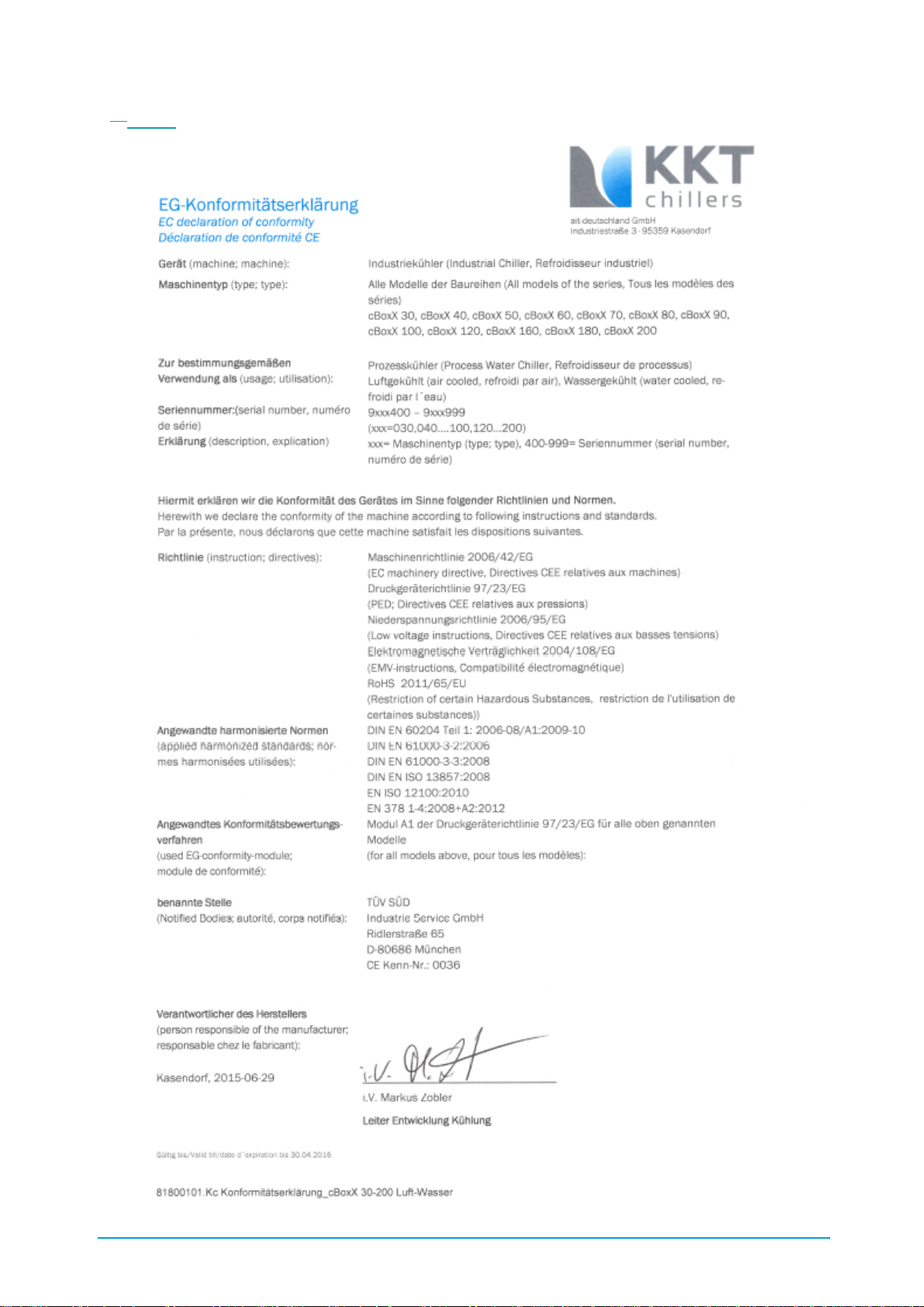
89 / 89 83000102.Ki
IV.VI. EC Declaration of Conformity
 Loading...