

Page 1
o
p
ge
s
p
ge
/
8
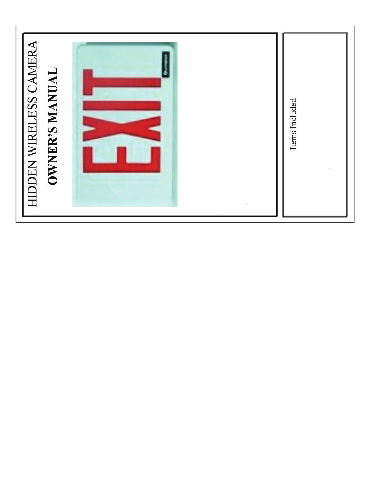
2.4 GHz Wireless
Exit Sign Camera
“Book” equipped with Hidden Camera and Transmitter
4 Channel Auto switching Receiver
1La
a
nt
Fr
RCA Video Cable
9V AC Adaptor
12V AC Adapter
a
t
TERMS AND CONDITIONS
Warranty Information
The manufacturer warrants their products to be free from defects in material or workmanship for a
period of one year from the date of the original purpose. The limited warranty stated above is subject
to these terms and conditions.
Limitation on Warranties: All merchandise carries a one (1) Year Manufacturer’s Limited Warranty on parts and labor. SELLER MAKES
NO WARRANTY, EXPRESSED OR IMPLIED, INCLUDING ANY WARRANTY OR FITNESS FOR ANY PARTICULAR PURPOSE OR
MERCHANTABILITY. No agent, employee or representative of Seller’s are authorized to bind the Seller to any affirmation, representa-
tion, or warranty, oral or written, unless by separate written instrument designed by Seller, which by its terms state that it is included as
part of this agreement.
Claims: Receipt of goods shall be deemed acceptance of the goods received. All claims for defective goods or revocation of acceptanc-
es, for shortages, for delays, or failures in shipment or delivery, or for any cause shall be deemed waived and released by the Buyer
unless it is made in writing within (7) days after receipt of goods. All claims must state specifically and in reasonable detail the nature of
all objections, and must be accompanied by delivery receipt or photocopy of the sales order or packing slip. Any delivery not placed in
dispute in a timely manner shall be paid for by the Buyer and all uncontested amounts due shall be paid by the Buyer with terms speci-
fied. As a condition to making a claim for missing or damaged goods sent, the Customer is responsible for initiating and pursuing with the
carrier.
Limitation on Seller’s Liability: Seller’s liability will be limited to replacement or repair of defective goods upon receipt of goods in a timely
manner per paragraph two herein. In no event will Seller be liable for consequential or special damages or for transportation, installation,
removal, adjustment or other expenses or losses which may arise in connection with the use or installation of the goods; late delivery,
failure to deliver or from any other cause. Not withstanding the terms of this Agreement, if there should arise any liability of Seller, such
liability shall be limited to an amount equal to one-half (1/2) the costs of the goods or $250.00, whichever is less.
Returned Material: In no case will the seller give a refund. Seller will accept most goods for exchange or credit, at the Seller’s discretion
within 30 days of purchase date. In no case are goods to be returned without first obtaining Seller’s permission. Only unused goods as
currently manufactured, in original unopened packaging and which has been paid for by Buyer in accordance with Seller’s payment terms
will be considered for exchange or credit upon receipt of proof of purchase. Special ordered items and obsolete items cannot be returned
for credit. Material accepted for credit will be subject to a 15% restocking charge for service and handling. Seller will not be obliged to
replace any product that has been abused, improperly installed or otherwise misused. Items must be returned in their original packaging,
securely packed to reach the Seller without damage.
Governing Law: This agreement shall be governed by the laws of the State of Tennessee.
IT IS THE USER’S RESPONSIBILITY TO ENSURE THAT THIS EQUIPMENT IS USED IN ACCORD-
ANCE WITH THE LAW(S) OF THE JURISDICTION IN WHICH THIS EQUIPMENT IS UTILIZED. THIS EQUIPMENT HAS BEEN TESTED AND HAS BEEN FOUND TO BE IN COMPLIANCE WITH THE
LIMITS FOR A CLASS B DIGITAL DEVICE, PURSUANT TO PART 15 OF THE FCC RULES. THESE
LIMITS ARE DESIGNED TO PROVIDE REASONABLE PROTECTIONS AGAINST HARMFUL INTER-
FERENCE IN A RESIDENTIAL INSTALLATION. THIS EQUIPMENT USES, GENERATES AND CAN
RADIATE RADIO FREQUENCY ENERGY AND IF NOT INSTALLED AND USED IN ACCORDANCE
WITH INSTRUCTIONS, MAY CAUSE HARMFUL INTERFERENCE TO RADIO COMMUNICATIONS. Part 15 Low Power:
ANY CHANGES OR MODIFICATIONS TO THIS EQUIPMENT WITHOUT THE EXPRESS AUTHORIZA-
TION OF THE MANUFACTURER COULD VOID THE USER’S AUTHORITY TO OPERATE THIS EQUIP-
MENT. (RULE 15.21 OF THE FCC)
FCC ID Number NGVAWV326T
Page 2

ge
ge
7
Wireless Exit Sign Camera!
Congratulations and thank you for purchasing the
This Exit Sign Camera is well-equipped with a completely undetectable,
high quality camera and selectable 4-channel 2.4 GHZ wireless transmitter.
Also included in this indispensable covert surveillance system are matching
Easy installation
Low light capabilities
High resolution camera
Additional features include:
interference from other wireless devices)
(LOS is dependent upon obstructions and
300 - 700 foot line-of-sight (LOS) approximate range
selectable 4-channel receiver and all necessary power adaptors.
User-friendly operation
FCC-approved 2.4 GHz transmitter
Upon reading through these instructions, you will be able to operate your
a covert video surveillance system.
state-of-the-art wireless Covert Camera even if you have never before used
NOTICE: In accordance with United States Codes, this unit is not
equipped with audio capabilities. It is illegal for non-authorized persons to
own, possess, or utilize surreptitious listening devices for the purpose of
intercepting and/or recording another person’s oral communications. Any
modifications made to this unit are unauthorized and will immediately void
the manufacturer’s warranty.
2 Pa
Pa
Page 3

p
ge
3
.
VIDEO
a
Figure 1
General Setup
Wireless Covert Camera
1. Install the Exit Sign Camera on a flat surface facing your target area. When
determining the best possible site selection, pay particular attention to lighting.
It is always best to have the lighting on or in front of your subject instead of
behind it.
2. Plug the power cord of the alarm clock into the nearest 110V AC outlet. Your
wireless covert camera should now be operating
For optimal performance, adjust the 2.4 GHz antenna on the receiver. Alt-
hough the units will still work properly without facing each other, transmis-
sion range may be decreased.
2.4 GHZ Receiver
1. Position the receiver within 150ft – 300 ft ( see LOS) of the covert camera.
power plug coming from AC adaptor into the back of the receiver. Red LED
will come on to indicate power.
2. Plug the included AC adaptor into a 110V wall outlet. Plug the 2.5mm male
located on the front of the receiver. (See Figure 1)
3. Connect the male yellow RCA cable plug into the female yellow RCA jack
Page 6
Page 4

ge
ge
5
found inside ????????????? .
twice for channel 3, or three times for channel 4.
Channel Selection
Your wireless transmitter and receiver have channel-select capabilities on four
channels. In order to capture video, transmitter and receiver must be on the
same channel.
1. To change the channel on the transmitter, push the black channel button
The unit is initially set to channel 1. Push the button once for channel 2,
switch of the appropriate channel down. All other channel switches must
remain up, as only one channel per camera may be selected.
2. To change the channel on the receiver, simply slide the channel select
may have inadvertently selected more than one channel. Adjust switches
NOTE: If your picture is going on and off every three to five seconds, you
to be sure that you have selected only one channel.
channel select switches, one per camera, into the down position. The re-
ceiver is auto-switch capable and should now switch every three to five
seconds between selected channels.
To use the receiver with multiple cameras, slide all of the appropriate
Safety Precautions
system.
- Use only the included power supply to operate your wireless surveillance
- To avoid electrical shock, do not attempt to open the unit.
- To prevent fire or shock hazard, do not expose this product to rain or
moisture. Do not operate near bath tub, sink, or swimming pool. Avoid
operation in moist environments.
fire or electric shock.
- Do not overload electrical outlets or extension cords as this may result in
Operation
end of the RCA video cable into the video input jack on your monitor or tele-
vision.
Once the Covert Camera is in place and aligned with the receiver, you must con-
nect the receiver to a monitor and/or video recorder to gain access to your video
footage. 1. To view video footage on a monitor or television, connect the unattached
.
into the video input jack on your VCR or video recorder according to manu-
facturer’s instructions
To record video footage, connect the unattached end of the RCA video cable
2. Change the video input or auxiliary input for your monitor or recorder until
video footage can be viewed. The input select button is usually located on the
unit’s remote control or on the front panel of the unit itself. However, some
units may require you to select the video input from the on-screen menu.
Therefore, consult the owner’s manual for your monitor or video recording
device for specific instructions.
ble from the video output jack on the recorder to a monitor or television.
If using a recorder, check video transmission by connecting another RCA ca-
any necessary adjustments to the receiver antenna for best reception.
3. Your monitor should now display the view from the Covert Camera. Make
Tip: If picture quality is not optimum, try selecting an alternative channel.
4 Pa
Pa
 Loading...