

Page 1
Specification
CM-DC10
Item Number
Video Signal
Number of Pixel
Resolution
S/N ratio
Image Sensor
Pixel size
Sensitivity
Video Output
Lens F/No
Focal Length
Angle of View
Power Supply Voltage
Camera Current
Dimension (Incld Lens)
CM-DC10
NTSC PAL
640x480 640x480
480 TV Line
38 dB
1/18 ˝
2.5µm x 2.5µm
4V(Lux•sec)
1.0V p-p
2.8
1 m - 10m
60 ˚ ± 2˚
DC 5V ± 0.5V
110mA
Ø5.6 x 46mm
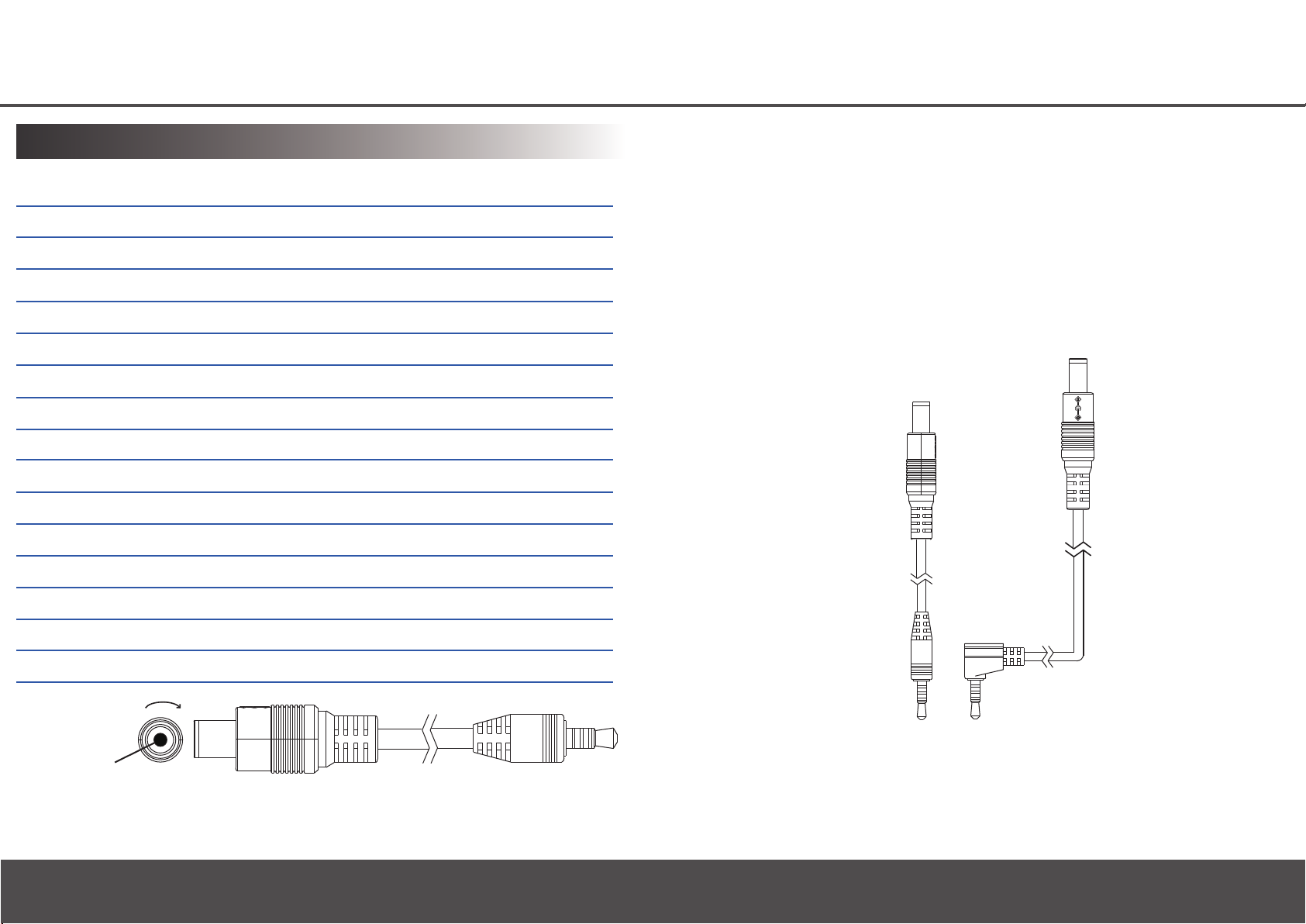
Adapter Connector Mini Camera
Quick Guide
Weight
Left Right
CMOS Lens
Direction Adjuster
*Specification and appearance may be subjected to change
without notice.
12g
Law Enforcement Products Manufacturer
LawMate
V1.0
Page 2
User Instruction:
CM-DC10 mainly uses to capture images. There are two
application methods to use this device:
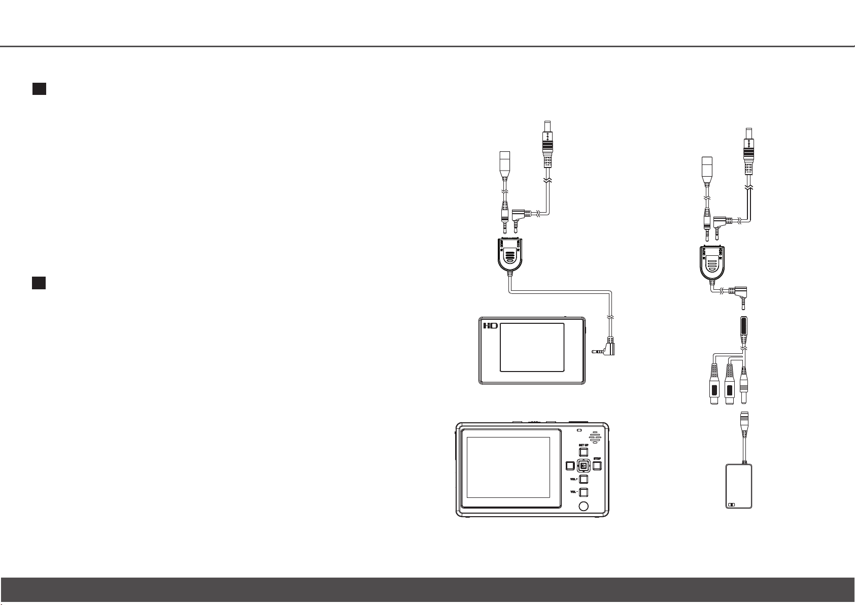
CM-DC10 can connect with a portable DVR:
1. Install the device same as Installation 1 shown on the left.
2. Insert CM-DC10 jack into A/V IN DC 5V OUT socket on DVR device.
Microphone is connected with Audio In socket, and CCD Camera
is connected with Video In socket on AV Switching Box.
3. Press POWER-ON button on portable DVR for 3 seconds and
release the button. Note that HOLD button should switch to left
when press POWER-ON button. You may adjust focus direction on adjuster.
4. A green light will turn on to show that DVR device is turn-on
properly. Press REC button to start recording.
5. Captured images are automatically shown on LCD display.
6. Audio and video signals are automatically collected into
recorded file on DVR.
CM-DC10 can also output captured audio and video signals
to an external display through AV switching cable:
1. Install the device same as Installation 2 shown on the left.
2. Slide the back cover of battery holder to open the
battery tray. Insert a PP3 (9V) battery with proper cathode/anode
direction into battery tray. Switch to ON indication. PP3
(9V) battery supplies power to the connected camera, CM-DC10.
3. The yellow and white color cable heads from switching cable
are to connect with the external audio and video jacks
from monitor/television. At the other end of switching cable
is a jack socket connected with jack of AV Switching Cable.
Microphone is connected with Audio In socket, and CCD
Camera is connected with Video In socket on AV Switching Box.
5. You may adjust focus direction on adjuster. Captured images are automatically
shown on the connected monitor/television.
6. Audio and video signals are automatically collected into the
recorder which connected with monitor/television. Noted that external
monitor/television is required to connect with an audio and
video recording device.Camera does not provide recording
function itself.
Connections Illustration
CM-DC10 connects to DVR
Installation 1
Camera
Direction Adjuster
Microphone
AV Switching Box
Optional Accessories
Portable DVR- PV-500EVO
Optional Accessories
Portable DVR- PV-1000
CM-DC10 AV output connection
Installation 2
Camera
Direction Adjuster
Microphone
AV Switching Box
Switching Cable
9V Battery Holder
 Loading...