

Kiyo GPS800 User Manual
USER MANUAL


1
1. PURPOSE OF THE GPS DETECTOR
The purpose of the device is to ensure the safe driving conditions, by
warning the driver to Fixed Speed Cameras, Section Control Zones,
Red Light Cameras and other risks. To do so, the detector uses a free
and upgradeable GPS database.
2. OPERATION OF THE DEVICE
After igniting the engine, the device powers on and starts connecting
to the GPS satellites. A short sound signal indicates the successful
connection and that the device is active. The detector displays the
current speed of the vehicle until it detects a speed camera. When a camera is
detected, the device signals to the driver
in the selected language and displays the
current distance to the speed trap.
With the optional Radar Detector module, the GPS Detector can also
indicate the location of mobile radar speed cameras. The device can
be hidden into the dashboard compartments or behind the dashboard itself; in such cases, the optional GPS antenna ensures the
stable connection to the satellites.
The driver can add new “Danger Zones” to the database of the device, for example, new speed camera locations or crossroads that the
driver found particularly dangerous.
2
3. INSTALLATION
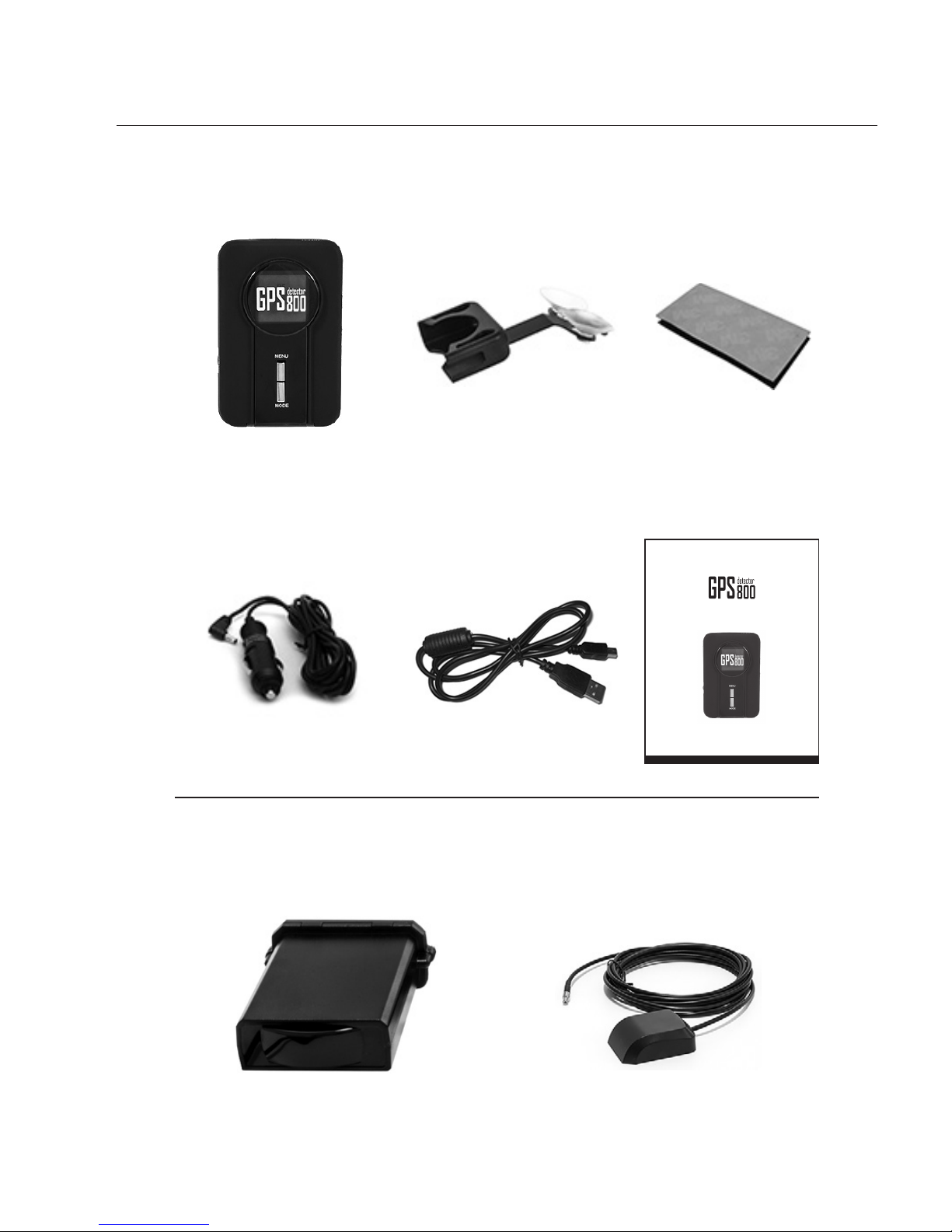
a) Accessories
Central Unit
Bracket Velcro tape
Cigarette Lighter Power
Cable (with a spare fuse)
USB Cable User Manual
USER MANUAL
Optional accessories
Radar Detector module GPS receiver
3
b) Finding the perfect location for the device
For the best efficiency, ensure that the logoed side of the device has
a clear view to the sky. Be warned that metallic parts might interfere
with the connection between the Detector and the satellites, therefore make sure that there are no such parts above the device. Do not
place the device where it may limit the driver’s view or where it can
cause injuries upon sudden braking.
If you wish to place the device below the dashboard or into certain
dashboard compartments, the separately purchasable GPS receiver
will ensure the connection between the satellites and the device.
WARNING! If your vehicle’s windscreen is metalized, the detector
can only function properly with the optional GPS receiver, because
the metallic components of the windscreen may interfere with the
connection between the detector and the satellites.
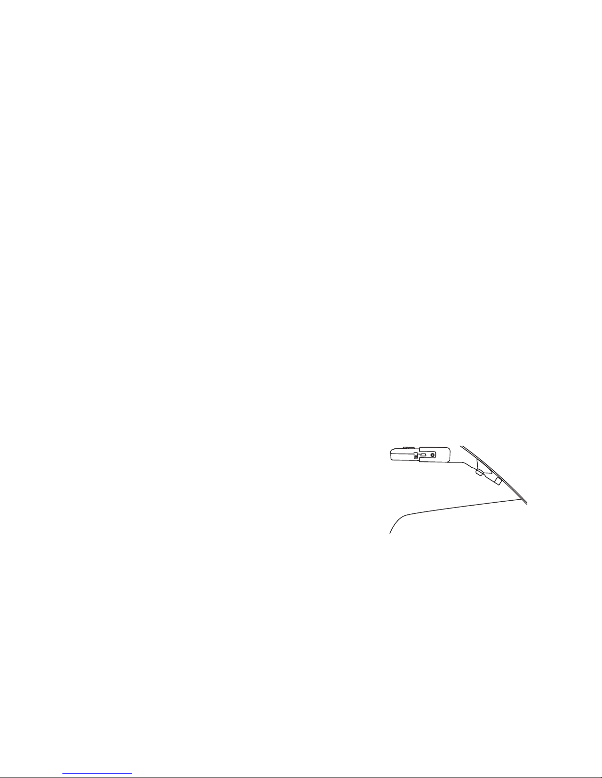
c) Mounting options
Mounting on windscreen
• Mount the bracket on the windscreen.
• Align the bracket until it is horizontal.
• Put the detector into the bracket.
• Attach the power cable to the device.
• Plug the power cable into a 12 V cigarette lighter socket.
When you leave the vehicle, remove the device from the bracket,
in this way you can avoid solar damages and other dangers. The
stealth installation may be more convenient and may even improve
the service life of the device.
4
WARNING! Some manufacturer might place a protective plastic film
on the windscreen of their latest vehicles. The bracket may leave
a mark on these windscreens; therefore check your vehicle’s user
manual for information regarding your windscreen.
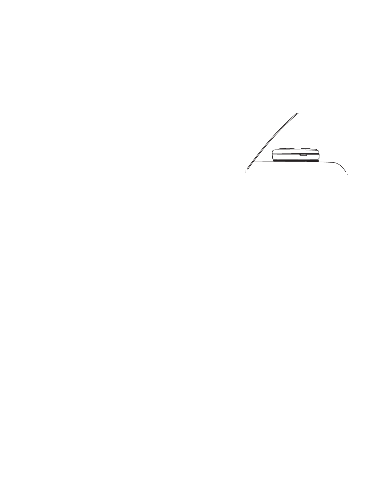
Mounting to dashboard
•
Locate a suitable mounting location and
clear that spot thoroughly.
•
Remove the protector foil from the Velcro
tape and attach it to the device.
•
Remove the protector foil from the Velcro tape attached to the device and mount the equipment on the selected and cleaned surface.
•
Connect the device and the cigarette lighter socket via the power
cable.
Stealth installation
Because the device at the same time displays the threat and gives
a voice signal in the selected language, it may be installed into hidden compartments. There are many places where it can be hidden,
for example, in the glove-box, in the car’s center console, into the
compartment of the armrest, or even below the dashboard. After
locating the given spot, follow the steps of the “Mounting to dashboard” section.
In case of a stealth installation, a GPS receiver is also necessary to
ensure the connection between the GPS Detector and the satellites.
For the best efficiency, the receivers should be placed to the lower
part of the windscreen. If the windscreen is metalized, the receivers
should be installed into the front bumpers.

5
d) Setting the device up
POWER USB OPT
VOL
•
The power cable of the cigarette lighter goes
into the POWER socket. (Vid: “Accessories”,
p.2.)
•
The mini USB connector of the USB cable goes
to the USB socket. (Vid: “Accessories”, p.2.)
•
The optional Radar Detector module can be attached to the OPT
socket. (Vid: “Connecting to the Radar Detector Module”, p.17.)
•
Connect the device to the vehicle’s cigarette lighter socket (DC 12-24
V) via the cigarette lighter power cable. If this socket is connected
to a constant current, the Detector will function when the car is not
moving. However, in this case, the device will drain the battery in
time, therefore, after use, you should turn the equipment off. If the
socket is connected to the ignition circuit, the Detector will turn off
when the ignition ceases, therefore it will not drain the battery.
e) Turning the Detector on
The device turns on when igniting the engine and starts searching
for the connection with the GPS satellites. This is displayed
on the screen of the device, once it is connected, the inscription will
disappear and the device is operational. A short greeting message in
the selected language can also be added to the startup of the device.
The time for finding the GPS signals for the first time may vary
depending on weather conditions, like the humidity of the air and
the temperature. In cities, signals reflected from certain objects may
also extend the searching time. Upon driving in tunnels or near tall
buildings, the device may lose the connection with the satellites and
display the searching text again, but it will reconnect in time.
6
WARNING! Without GPS connection, most of the device’s functions
are disabled. (e.g.: SMART MUTE, GPS database, etc…)
4. USE OF THE GPS DETECTOR
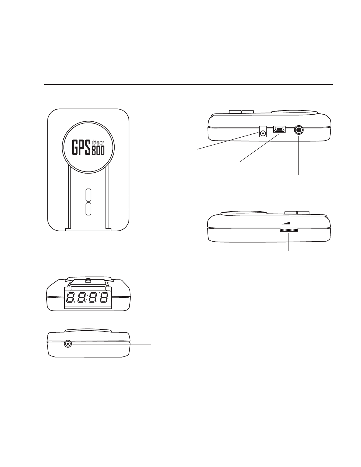
a) Controls of the GPS Detector
POWER USB OPT
MENU
MODE
VOL
POWER USB OPT
MENU
MODE
ANT.EXT
VOL
POWER USB OPT
MENU
MODE
ANT.EXT
VOL
POWER USB OPT
VOL
VOL
MENU button
MODE button
Display
Power socket
USB socket
Volume Control
GPS ANTENNA socket
Radar Detector Module
socket
b) Settings
The settings of the device can be adjusted in the menu system, with
the MENU and MODE buttons. (vid: “c) Functions of the GPS Detector”, p.8-13.)
 Loading...