

Kiva Lighting Sheridan, Pine Valley, Mountainair, Old Forge Owners & Installation Manual
Owners & Installation Manual
for the
Sheridan, Mountainair, Pine Valley
and Old Forge Ceiling Fan Family
Part of the Kiva Lighting Family
Custom Lighting and Fans Since 1992
1312 12th St NW Albuquerque, NM 87104
Your Western, Rustic and Specialty Ceiling Fan Source
(505) 342 - 9044

READ AND SAVE THESE INSTRUCTIONS
Over 90% of ceiling fan problems are the result of improper installation. Ceiling
fans are complicated, sensitive and precision products that must be treated with re-
spect and care during installation. If there are any problems, please see the trouble-
shooting section at the end of this manual.
Before beginning installation of your new Copper Canyon ceiling fan, please read and follow these
safety instructions. If you are not familiar with national/local electrical codes and basic electrical procedures, we recommend that you have a qualified electrician install your new ceiling fan. We are not responsible for any damage to your fan caused by improper installation.
Important Safety Considerations
TURN OFF THE ELECTRICITY before starting fan installation. Determine which circuit your new fan
will be using and remove the fuse or turn off the circuit breaker at the main panel.
Make sure that all wiring conforms to national and local electrical codes. If you are in question, ob-
tain a copy of the codes and wire the fan accordingly. Never leave bare wires uncovered and all
wire connections should have wire nuts to cap all connections. Plastic electrical tape is NOT rec-
ommended.
When working with electricity never take short cuts. Follow the code in every respect. Basic re-
quirements for a ceiling fan installed with lights are 120 volts AC – 60Hz on a grounded circuit
with a 15 amp breaker or fuse. Make sure that your electrical system and choice of location meet
these requirements.
If you plan to use an existing electrical location, check to make sure that the outlet box is NOT
plastic, that it is securely attached to a wood ceiling joist and able to support at least 50 lbs of moving weight. If you have any questions regarding these requirements, outlet boxes and support systems for ceiling fans you may get more information at your local Hardware store or Home center.
In most cases, your dealer will also have all the necessary knowledge and products for the proper
and safe installation of your ceiling fan.
If the location where you plan to install your fan does not already have an electrical outlet, hire a
licensed electrician to run the wiring and install an outlet box designed for a ceiling fan or any
heavy fixture. The outlet box should be able to support a minimum moving weight of 50 lbs. and be
marked “acceptable for fan support”.
The fan should be located in a spot that has a minimum of 30 inches between the wall and tip of the
fan blade at any point in its rotation. There should be a minimum of 7 feet from the blade level to
the floor to minimize any accidental contact with the fan.
Attach fan blades after the fan body has been properly mounted to the ceiling.
Lubrication will not be necessary in your new ceiling fan. The ball bearings have been greased and
permanently sealed at the factory so that further attention will not be necessary.
Every effort has been made to provide you with proper instructions for the safe installation of this
ceiling fan. You could, however, encounter situations or problems not covered in the manual.
Should this occur, please refer to an electrical wiring handbook or hire a qualified electrician to install your fan.

WARNING
To reduce the risk of fire, electrical shock and personal injury – mount this fan to an outlet box
marked “acceptable for fan support” using the mounting screws provided with the outlet box only.
To reduce the risk of personal injury, take care to not bend the blade arms or blades. Be careful not to
insert foreign objects into rotating fan blades.
The important safeguards and instructions appearing in this manual are not meant to cover all possible
conditions and situations that may occur. It must be understood that common sense, caution and careful attention to detail are factors which cannot be built into this product. These factors must be supplied by the person or persons installing, caring for and operating the unit.
Look for:
To find safety tips and ideas for installation.
These instructions are designed for a number of similar, but different, ceiling fans. As you proceed, some steps may or
may not apply to the fan you purchased. Compare each step or optional procedure to your fan and proceed accordingly.
Please follow these Minimum fan mounting
Guidelines. Fans with light kits will require an
additional 8-12 inches of ceiling height
Figure 1
Figure 2
Have you turned OFF the
ELECTRICITY to the Fan?
STEP 1: Install the included 4-25W light bulbs in the top of the fan
(figure 1)
Do not use any size larger than 25 Watts or the fan will overheat.
STEP 2: Attach the Support Assembly
Loosen the set screws (2) in the support rod coupler located on
the top center of the motor housing (figure 2) until the inside
channel is clear.
Note: If a longer down rod is being used, transfer the hanging
ball to the new down rod and tighten the screws and pin securely
Remove and save the hair pin clip and clevis pin from the cou-
pler.
Place the ceiling canopy decorative strip coupling cover onto
support rod. Slide the cover onto support rod. (figure 2)
Thread the support rod into the support rod coupler until the
clevis pin can be inserted through the hole in both the rod and
coupler. DO NOT TIGHTEN PAST THIS POINT OR YOU
WILL CUT THE WIRES AND VOID THE WARRANTY.
Insert the clevis pin through the hole in the support rod coupler
and support rod; tighten firmly.
Tighten the two set screws in the coupler; tighten firmly so the
pipe will not twist or come loose.
Canopy Mounting
Screws
Figure 3
Figure 4
Figure 5
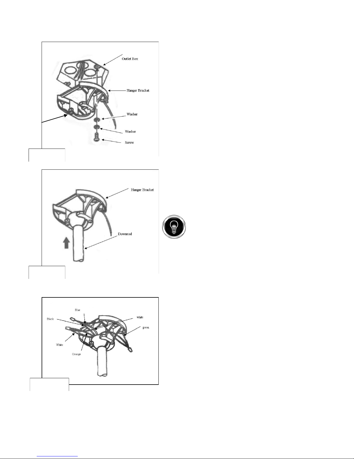
STEP 3: Attach the Mounting Bracket
Loosen the 2 small canopy mounting screws on the downside
face of the hanger bracket. Back them out about halfway, this will
allow for easier installation of the ceiling canopy later. (figure 3)
Install the hanger bracket on the electrical junction box in the
ceiling using 2 machine screws, 2 washers and 2 lock washers.
(figure 3) The mounting bracket has slotted holes to enable it to
move sideways for a proper alignment. Make sure the mounting
bracket is centered over the electrical junction box and that it is
securely attached. (figure 3)
STEP 4: Hanging the Fan Body
Notice the half ball on the end of the support rod is grooved down
one side. (figure 4) This keyway fits over the small keyway pin
on the inside of the mounting bracket and keeps the ceiling fan
from spinning on the mounting bracket.
Using a ladder, lift the fan and place the half ball in the center of
the mounting bracket with keyway pin inserted in the keyway of
the ball.
Turn the fan left and right slightly to make sure it is seated on the
bracket with the keyway pin in the keyway. Trim the lead wires,
leaving about 6 inches of each wire extending from the support
rod.
When using an optional longer down rod, be sure to attach the half ball properly with the clevis pin through the
rod and the set screw tightened down. These parts have to
be removed from the 4-5” rod included with the fan.
STEP 5: Making the Electrical Connections
In order to operate your ceiling fan with both pull chain(s) and
switches mounted on your fan – follow the instructions below. If using
wall switches or a remote control, please refer to the wiring diagrams
at the back of this manual.
Attach the GREEN wire (connected to the half ball) to the
GROUND wire in the junction box. The GROUND wire is usually a bare copper wire without plastic insulation. It could also be
covered in green plastic insulation or attached to the metal junction box in the ceiling. (figure 5)
Attach the BLACK wire and the BLUE wire from the ceiling fan
to the BLACK wire in the junction box.
Attach the WHITE wire and the ORANGE wire from the fan to
the WHITE wire in the junction box.
Fold the connected wires (figure 5) and push them up inside the
electrical junction box with the black and blue wires to one side
and white and orange wires to the other side.
Make sure the wire nuts do not come loose during this operation
and that the wires are still tightly bound together inside the wire
nut.
Note: a common problem is when one of the wires pulls out of
the wire nut when pushing the wires into the box.
 Loading...