

Page 1
HARNESS THE POWER OF THE SUN WITH THIS
ESSENTIAL
INFORMATION
BUILD INSTRUCTIONS
CHECKING YOUR PCB & FAULT-
FINDING
MECHANICAL DETAILS
WORKS
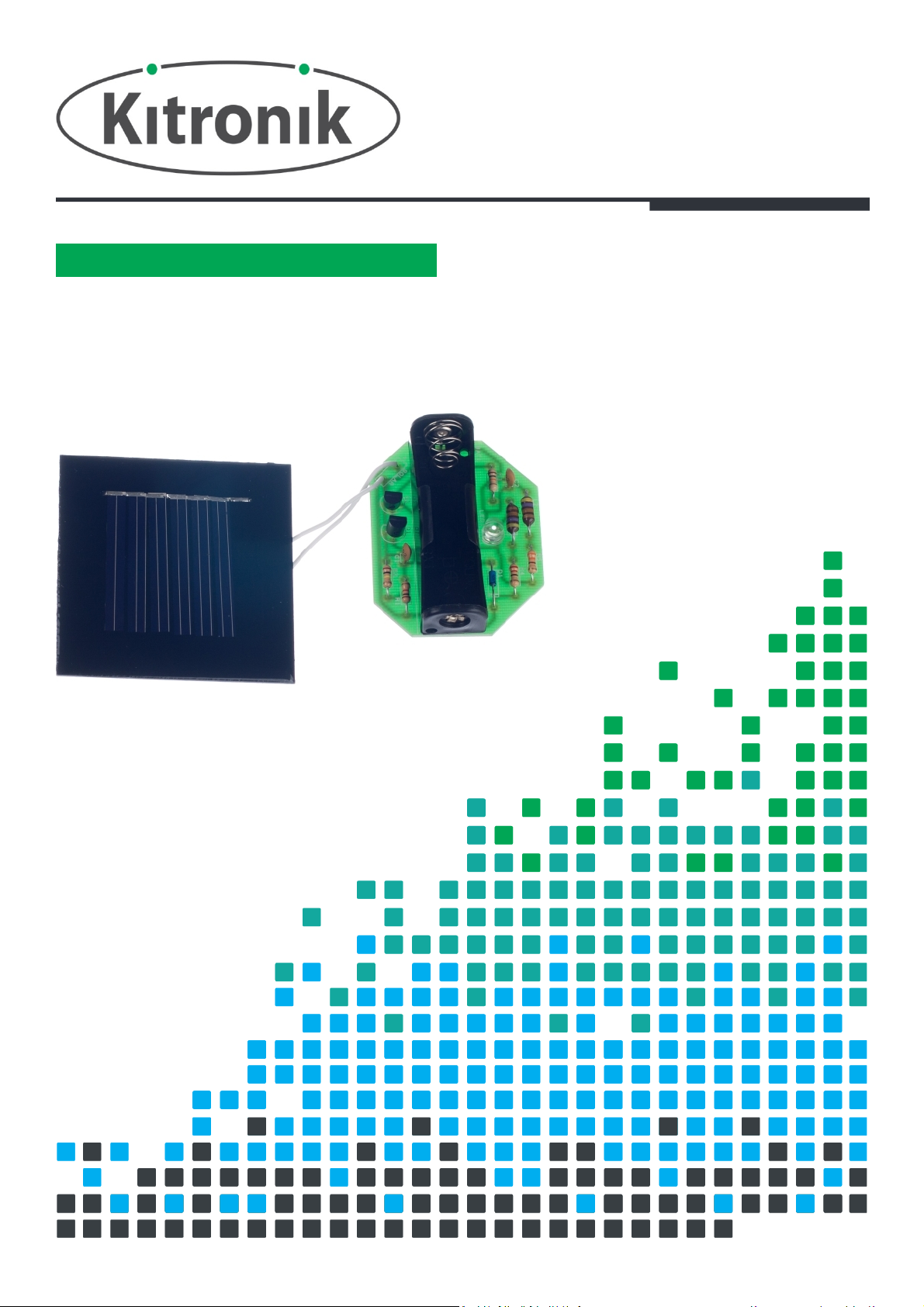
SOLAR GARDEN LIGHT KIT
HOW THE KIT
Version 2.0
Page 2

Solar Garden Light Essentials
PCB Ref
Value
Colour Bands
R11KBrown, black, red
R2
100K
Brown, black, yellow
R3
10K
Brown, black, orange
R4 22
Red, red, black
R5
330Orange, orange, brown
PLACE RESISTORS
1
SOLDER THE DIODE
2
SOLDER THE INDUCTORS
3
SOLDER THE CAPACITORS
4
SOLDER THE TRANSISTORS
5
www.kitronik.co.uk/2134
Build Instructions
Before you start, take a look at the Printed Circuit Board (PCB). The components go in the side with the writing on
and the solder goes on the side with the tracks and silver pads.
Start with the three resistors:
The text on the PCB shows where R1, R2 etc go.
Ensure that you put the resistors in the right place.
Solder the diode into the board where it is labelled D1. It is important that the diode is inserted the
correct way around otherwise it will not work. If you look closely at the diode, you will see that it
has a black band at one end. This should match the outline on the PCB.
Solder the two inductors into the PCB where it is labelled L1 and L2. The inductors look like the
resistor but are slightly larger. It doesn’t matter which way around the inductors go into the PCB.
Solder the two 1nF capacitors into the PCB where it is labelled C1 and C2. The capacitors can be
identified by the text ‘102’ which is written on them. It doesn’t matter which way around they are
put into the PCB.
Solder the two transistors into the PCB where it is labelled Q1 and Q2. The transistors have to be
inserted the correct way around to work. Make sure that the outline of the component matches
the outline on the PCB.
Page 3
Solar Garden Light Essentials
SOLDER THE LED
6
SOLDER THE BATTERY HOLDER
7
CONNECT THE SOLAR CELL
8
INSERT THE
BATTERY
9
www.kitronik.co.uk/2134
Solder the LED (Light Emitting Diode) into the PCB where it is labelled LED1. The LED has to be
inserted the correct way around to work. Make sure that the outline of the component matches the
outline on the PCB (the LED has one flat edge). Depending on your enclosure design, you may wish
to mount the LED at a specific height above the PCB or on wire leads.
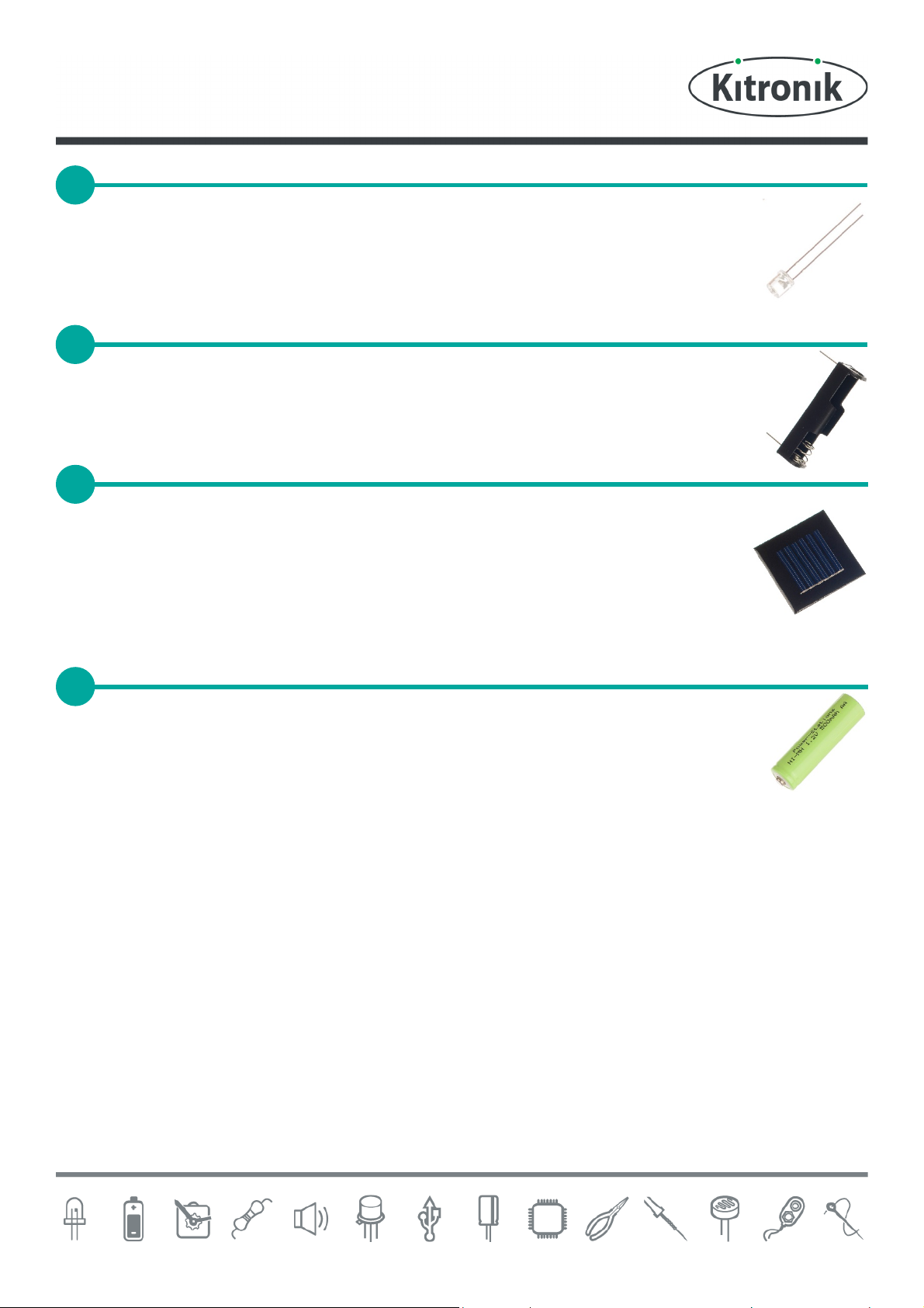
Solder the PCB mount battery holder into the PCB where it is labelled BAT1. The battery holder has
to be inserted the correct way around to work. The markings on the PCB show where the ‘spring’
end of the battery holder goes.
Next connect the solar cell to the PCB. First, look at the back of the solar cell. There are markings
to show which are the ‘+’ terminals and which are the ‘-’ terminals. Now look at the PCB and you
will see that the terminals labelled ‘solar’ also have labels to indicate which is ‘+’ and which is ‘-’.
In the kit there is a bundle of wire. Use two lengths of this to connect each of the terminals on the
PCB to the corresponding terminal on the solar cell. The solar cell has terminals that have already
been tinned with solder and you will find these the easiest to solder to.
The last job is to insert the rechargeable battery (the battery holder indicates which way around the
battery goes). Before you insert the battery please go through the ‘Checking your solar light PCB’
section on the right.
Page 4

Solar Garden Light Essentials
www.kitronik.co.uk/2134
Checking Your Solar Light PCB
Carefully check the following before you insert the battery:
Check the bottom of the board to ensure that:
All holes are filled with the lead of a component.
All these leads are soldered.
Pins next to each other are not soldered together.
Check the top of the board to ensure that:
The flat edges on the LEDs and transistors match the outlines on the PCB.
The band on the diode matches the corresponding outline on the PCB.
The spring end of the battery holder is next the ‘BAT1’ text on the PCB.
The positive connection on the solar cell is connected to the positive ‘solar’ terminal on the PCB and the
negative connection on the solar cell is connected to the negative ‘solar’ terminal on the PCB.
Fault Finding
Page 5

Solar Garden Light Essentials
www.kitronik.co.uk/2134
Fault Finding
With a battery that has
some charge in it fitted,
cover the solar cell
Yes, but
dimly
R4 & R5 are
in the wrong
place
solar cell, does the
Start
Does
the LED
light?
Yes
Uncover the
LED go off?
Yes
No
No
Fault finding flow chart
Check
R3, R4 & R5 for dry joints.
All the resistors are in the right place.
C2 for dry joints or a short.
D1 is the right way around.
L1 & L2 for dry joints
The LED is in the right way round, for
dry joints & short.
The battery holder is in the right way
around and for dry joints.
Q1 for a short.
Q2 for dry joints, shorts & that it is in
the right way around.
Check
R1 for dry joints.
R1 & R2 are in the right place.
C1 for a short.
The solar cell is in the right way around
and for dry joints.
Q1 for dry joints or shorts
Does the LED
turn on at the right
light level?
Yes
Does the
battery charge
during the day?
Yes
Stop
No
No
It is dark before the LED comes on
There is a dry joint on R2
The LED turns on when it is still light
There is a dry joint on Q1
There is a dry joint on D1
Page 6

Solar Garden Light Essentials
60
www.kitronik.co.uk/2134
Designing the Enclosure
When you design the enclosure, you will need to consider:
The size of the PCB (below left).
The size of the solar cell (below right).
Where the LED is mounted (shown in the top middle of the PCB).
60
All dimensions in mm.
The diameter of the LED is 5 mm and the total height of the unit approximately 15mm.
The LED can be mounted on flying leads if you want to position it away from the PCB.
Mounting the PCB to the
enclosure
The drawing to the left
shows how a hex spacer
can be used with two
bolts to fix the PCB to the
enclosure.
Your PCB has four
mounting holes designed
to take M3 bolts.
Page 7

Solar Garden Light Essentials
www.kitronik.co.uk/2134
How the Solar Garden Light Works
The garden light uses a solar cell to charge a
rechargeable battery during the day. At night,
when the light level has dropped, the circuit
switches from charging the battery to discharging
the battery through a high brightness LED.
The solar cell and the diode form the parts used to
charge the battery. When sunlight shines on the
solar cell, it produces enough power to charge the
battery. The diode is used to stop the battery
discharging back (as it only allows electricity to
flow in one direction) into the solar cell if there is
not enough sunlight falling upon (and therefore
not enough voltage generated by) the solar cell.
Resistors (R1) and (R2) and transistor (Q1) form the part of the circuit that switches the LED on when the light level
has fallen below the desired level.
When there is sunlight on the solar cell, the voltage it produces is enough to turn transistor (Q1) on (this keeps the
LED turned off). As the amount of sunlight falls, the voltage it produces falls until there is not enough to keep
transistor (Q1) turned on. The resistors (R1) and (R2) form a potential divider, which is used to feed only a
proportion of the voltage produced by the solar cell through to the transistor. This allows the point where the LED
comes on to be fine-tuned to the desired level.
Once activated, the remaining parts are used to power the LED. The LED requires around 3V to work but the battery
can only supply about 1.2V. In order to generate 3V for the LED, the circuit has been designed so that the LED is not
always on but when it is, 3V can be supplied.
This happens so fast that to the human eye, the LED
looks like it is always on. The inductor (L2) and the
capacitor (C2) form a resonant circuit that produces
an alternating signal as shown in the picture above.
When this alternating signal produces a voltage
above 0.7V it turns on the transistor (Q2), which
keeps the LED off. When this voltage drops below
0.7V, the transistor turns off and the LED comes on.
When it is on the inductor (L1), which has been
storing an amount of electricity, discharges into the
LED at the same time as the battery which produces
the extra voltage needed to give the 3V for the LED.
The resistors (R4) and (R5) have been selected to reduce the amount of power the LED drive circuit uses. This helps
to extend the battery life so that the light can last about ten hours from a good days charging in the summer. When
there is less daylight in winter, this time will be reduced.
Page 8

Online Information
This kit is designed and manufactured in the
UK by Kitronik
Two sets of information can be downloaded from the product page where the kit can also be reordered from. The
‘Essential Information’ contains all of the information that you need to get started with the kit and the ‘Teaching
Resources’ contains more information on soldering, components used in the kit, educational schemes of work and so
on and also includes the essentials. Download from:
www.kitronik.co.uk/2134
Every effort has been made to ensure that these notes are correct, however Kitronik accept no responsibility for
issues arising from errors / omissions in the notes.
Kitronik Ltd - Any unauthorised copying / duplication of this booklet or part thereof for purposes except for use
with Kitronik project kits is not allowed without Kitronik’s prior consent.
 Loading...