


MASTER THE ART OF SOLDERING WITH THIS
REAR BIKE
LIGHT KIT

BUILD INSTRUCTIONS
Before you start take a look at the Printed Circuit Board (PCB). The components
go in the side with the writing on and the solder goes on the side with the tracks
and silver pads.
PLACE RESISTORS
1
Start with the three resistors. The text on the
PCB shows where R1, R2 etc go. Make sure
that you put the resistors in the right place.
PCB Ref
R1&R2
R3
PLACE THE TRANSISTORS
2
Place the two transistors into the board where it
is labelled Q1 and Q2. Make sure the device is the
correct way around. The shape of the device
should match the outline on the PCB.
PLACE THE CAPACITORS
3
Place the two capacitors into the board where it is
labelled C1 and C2. Make sure the device is the
correct way around. The capacitors have a ‘-’ sign
marked on them which should match the same sign
on the PCB. Once the legs have been pushed through
the board the capacitor should be folded flat against
the PCB before it is soldered into place.
Value
470K
33Ω
Colour Bands
Yellow, purple, yellow
Orange, orange, black
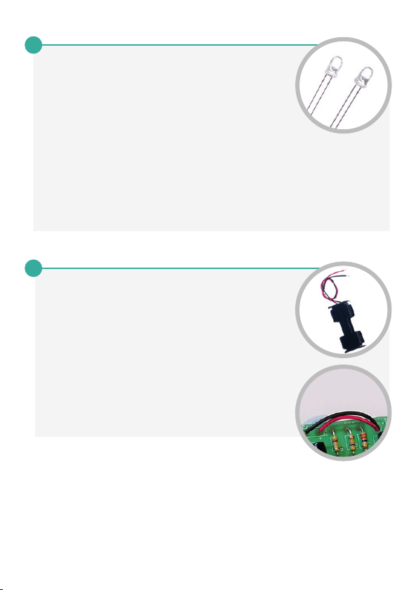
SOLDER THE LEDs
4
Place the two Light Emitting Diodes (LEDs) into
LED1 and LED2. It does not matter which goes
where, but the light won’t work if they don’t go in
the right way around. If you look carefully one side
of the LED has a flat edge, which must line up
with the flat edge on the lines on the PCB. You
may want to solder them in at a specific height
depending upon how you have designed your
enclosure (if you are making one). Once you are
happy solder them into place.
FIT THE BATTERY HOLDER
5
Finally you must attach the battery holder. Start by
feeding the leads through the strain relief hole near
R3. The wire should be fed in from the rear of the
board (see lower image).
The red lead should be soldered to the ‘+’ terminal
(also marked with the text ‘red’) and the black lead
should be soldered to the ‘-’ terminal (also marked
with the text ‘black’).

ADDING AN ON/OFF SWITCH
If you wish to add a power switch, don’t solder both ends of the battery cage
directly into the board, instead:
1
Solder one end of the battery cage to the PCB,
either black to ‘-’ or red to ‘+’.
2
Solder the other end of the battery cage
to the on / off switch.
3
Using a piece of wire, solder the remaining
terminal on the on / off switch to the
remaining power connection on the PCB.

CHECKING YOUR BIKE LIGHT PCB
Carefully check the following before you insert the batteries:
-
Check the bottom of the board to ensure that:
-
All holes (except the 4 large (3 mm) holes in the corners) are
filled with the lead of a component.
-
All these leads are soldered.
-
Pins next to each other are not soldered together.
-
Check the top of the board to ensure that:
-
The shape of the transistors match the outline on the PCB.
-
The flat edge of each of the LEDs matches the outline on the PCB.
-
The ‘-’ on the capacitors match the same marks on the PCB.
-
The colour bands on R3 are orange, orange and black.
-
The battery cage red and black wires match the red & black text on
the PCB.
MECHANICAL DETAILS
48.5
4
12.75
12.75
4 x 3.3mm diameter mounting holes
4
2 x LEDs 5mm diameter
25.5
4
4
Dimensions in mm

HOW THE BIKE LIGHT WORKS
Batteries
R1
LED1
C1
Q1
R3 R2
LED2
C2
Q2
The circuit has two states which it alternates between. In each of the states one
of the LEDs is on while the other is off.
V+
R1
C1
0V
R3
LED1
V+
R2
C2
0V
R3
LED2
State 1 (see picture above):
Q1 is turned on which connects LED1
and C1 to 0V. This turns LED1 on and
C1 starts to charge through the
resistor R1 causing the voltage across
it to increase (it starts at less than
is turned off. This means LED2 is not
connected to 0V and is therefore
turned off. C2 (which has more than
0.7V across it) is gradually discharging
into the base of Q1.
0.7V). The voltage at the base of Q2
starts to rise as C1 charges as they
are both connected to each other.
This continues until the C1 has
sufficient charge to produce a voltage
>0.7V on the base of Q2, which causes
As C1 has less than 0.7V across it Q2
it to turn on.

HOW THE BIKE LIGHT WORKS
V+
R2
C2
0V
R3
LED2
V+
R1
C1
0V
R3
LED1
State 2 (see picture above):
Q2 is now turned on which connects
they are both connected to each other.
LED2 and C2 to 0V. This turns LED2
on. This connection of C2 to 0V causes
the voltage across it to drop below
0.7V turning off Q1. Now C2 starts to
charge through the resistor R2
causing the voltage across it to
increase. The voltage at the base of
As C2 has less than 0.7V across it Q1
is turned off. This means LED1 is not
connected to 0V and is therefore
turned off. C1 (which has more than
0.7V across it) is gradually discharging
into the base of Q2.
Q1 starts to rise as C2 charges as
The right hand side of the circuit is in the same state that the left hand side
started in Stage 1, but with C2 charging instead of C1. When the charge gets
high enough the circuit flips back to Stage 1.
R3 is needed to limit the amount of current flowing through the LED. The
transistors aren’t turned fully on so also contribute to the limiting of current
flowing through the LED. This means the current limit resistor is smaller than
it would otherwise be.
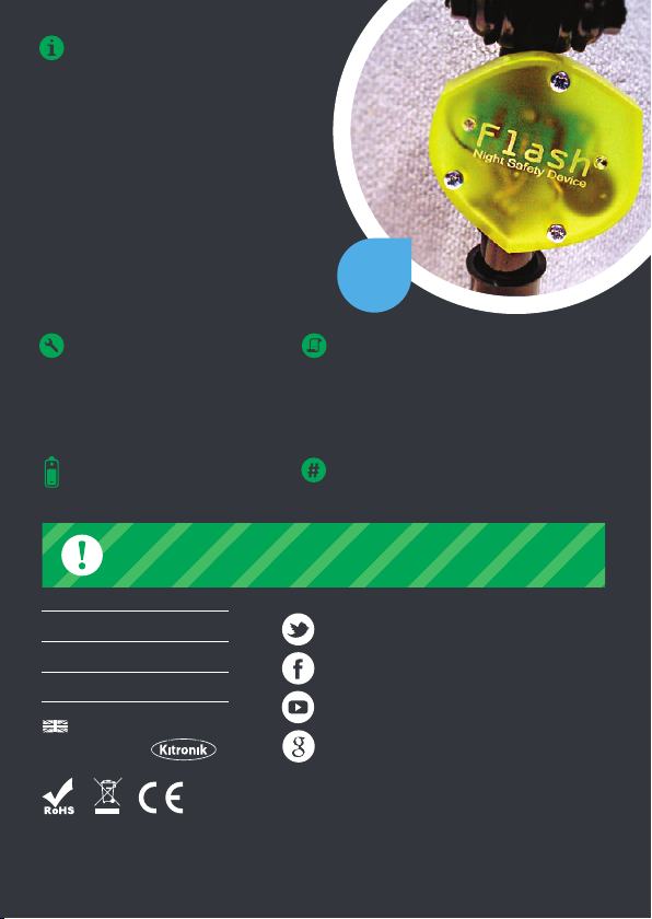
This easy build bike light kit has just ten
parts, making it a good introduction to
electronics. The kit uses two ultra
bright red LEDs, which flash rapidly,
providing a highly visible light. Making it
ideal for use as a rear bike light.
Note: We recommend this rear bike
light is used in conjunction with a
commercially available light.
TOOLS REQUIRED:
- Soldering Iron
- Solder
- Wire Cutters
KIT REQUIRES
2 x AA batteries
Example
Use
INSTRUCTIONS:
This booklet contains build instructions
and a circuit explanation. For more
detailed resources please visit our
website at www.kitronik.co.uk/2106
STOCK CODE
2106 or 1006 (Retail Version)
WARNING: Contents may inspire creativity
0845 8380781T:
www.kitronik.co.ukW:
support@kitronik.co.ukE:
Designed & manufactured
in the UK by
For more information on RoHS and CE please visit kitronik.co.uk/rohs-ce. Children
assembling this product should be supervised by a competent adult. The product contains
small parts so should be kept out of reach of children under 3 years old.
kitronik.co.uk/twitter
kitronik.co.uk/facebook
kitronik.co.uk/youtube
kitronik.co.uk/google
 Loading...