

Page 1
MP3 audio amplifier
Build Instructions
Issue 2.0
Page 2
Audio Amplifier
www.kitronik.co.uk
Build Instructions
Before you put any components in the board or pick up the soldering iron, just take a look at the
Printed Circuit Board (PCB). The components go in the side with the writing on and the solder goes on
the side with the tracks and silver pads.
You will find it easiest to start with the small components and work up to the taller larger ones.
Step 1
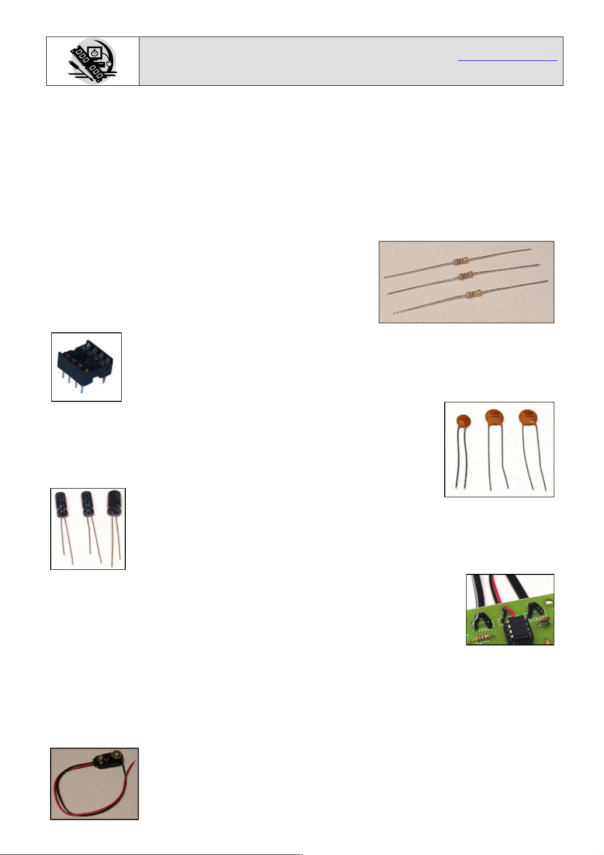
Start with the three resistors (shown right):
R1 is a 10K (brown, black, orange coloured bands)
R2 is a 100 (brown, black, brown coloured bands)
R3 is a 1 (brown, black, gold coloured bands)
The text on the PCB shows where R1, R2 & R3 go. Make sure that
you put the resistors in the right place.
Step 2
Solder the Integrated Circuit (IC) holder in to IC1. When putting this into the board, be
sure to get it the right way around. The notch on the IC holder should line up with the
notch on the lines marked on the PCB.
Step 3
There are three ceramic disc capacitors, the smaller one is a 470pF capacitor
and is printed with the number 471. This should be soldered into C1. The other
two capacitors are 100nF capacitors and are printed with 104. These need
soldering in to C2 and C3.
Step 4
The other three capacitors are electrolytic capacitors, the two smaller capacitors are
marked 100F. Place these two capacitors in to the board where it is labeled C4 and
C5. Make sure the device is the correct way around. The capacitors have a ‘-’ sign
marked on them which should match the same sign on the PCB. The bigger
capacitor is a 220F, which should be soldered in to C6.
Step 5
The three connections to your amplifier PCB need to go through the strain relief
holes as shown in the picture on the right.
Start with the connection labeled Speaker. The kit is supplied with ½ a meter of
twin cable with a 3.5mm Jack connector on one end. This cable will be used to
connect both the speaker and the MP3 player. You will need to cut a length from the end that does
not have the jack connector on which will be used to connect the speaker. Make sure you leave
enough cable so that you have a long enough lead to connect your MP3 player!
Take the piece of wire that you have cut off and strip the ends of the wire. Connect one end to the
two terminals on the speaker and the other end to the board marked speaker. It does not matter
which way around these connections go.
The middle connection is for the power. The PP3 battery clip (shown left) should be
attached to the power connection. Connect the red wire to ‘+’ and the black
wire to ‘-’.
Page 3

Audio Amplifier
www.kitronik.co.uk
Build Instructions (continued)
The final connection is the audio input. Strip the insulation off the other end of the remaining cable
that has the jack plug on. Run some solder in to the wire and trim the wire so only 2 or 3 mm of bare
wire is left. Solder these wires into the board where it is labeled ‘input’. It doesn’t matter which of the
pair of wires goes each of the two pads.
Step 6
The IC can now be put into the holder ensuring the notch on the chip lines up with the notch on the
holder. Your amplifier is ready for use. You can use the volume control on your MP3 player to control
how loud the amplifier is. Just make sure it’s mid volume when you test the amplifier.
Adding an on / off switch
If you wish to add a power switch, don’t solder both ends of the battery clip directly into the board,
instead:
Solder one end of the battery clip to the PCB, either black to ‘-’ or red to ‘+’.
Solder the other end of the battery clip to the on / off switch.
Using a piece of wire, solder the remaining terminal on the on / off switch to the remaining power
connection on the PCB.
Checking Your Amplifier PCB
Carefully check the following before you insert the batteries:
Audio equipment may become damaged if connected to an incorrectly built amplifier.
Check the bottom of the board to ensure that:
All holes (except the 4 large (3 mm) holes in the corners) are filled with the lead of a component.
All these leads are soldered.
Pins next to each other are not soldered together.
Check the top of the board to ensure that:
The three wires are connected to the right place.
The ‘-’ on the capacitors match the same marks on the PCB.
The colour bands on R1 are brown, black, orange & R2 are brown, black, brown.
The battery clip red and black wires match the red & black text on the PCB.
The notch on the IC is next to the power connection.
Page 4

Fault finding
Fault finding
flow chart
flow chart
Check
Check
• IC1 is in the right way around
• IC1 is in the right way around
• For dry joints on the power /
• For dry joints on the power /
speaker / input connectors
speaker / input connectors
• The input connector is in the
• The input connector is in the
right place
right place
• IC1 for dry joints on one of the
• IC1 for dry joints on one of the
following pins 3, 4, 5, 6, or 7
following pins 3, 4, 5, 6, or 7
• IC1 for shorts between pins 3-
• IC1 for shorts between pins 34, 5-6, or 7-8
4, 5-6, or 7-8
• C1, C4, C5 & C6 for shorts
• C1, C4, C5 & C6 for shorts
• C6 for dry joints
• C6 for dry joints
• C1 and C6 are in the correct
• C1 and C6 are in the correct
place
place
No
No
No
No
Does it “pop”
Does it “pop”
when the power
when the power
is connected?
is connected?
Yes
Yes
Audio Amplifier
www.kitronik.co.uk
Start
Start
Power up the board with it
Power up the board with it
connected to a music source
connected to a music source
Is the speaker
Is the speaker
making any kind
making any kind
of sound?
of sound?
Yes
Yes
Check
Check
• The power clip &
• The power clip &
batteries are
batteries are
connected the right
connected the right
way around
way around
• C1 is in the correct
• C1 is in the correct
place
place
• The speaker &
• The speaker &
power connections
power connections
are in the right
are in the right
place
place
IC1 for a short between pins
IC1 for a short between pins
2-3
2-3
R1 & R2 are in the right
R1 & R2 are in the right
place.
place.
• For a dry joint on C4, R2 or
• For a dry joint on C4, R2 or
IC1 pin 2.
IC1 pin 2.
• IC1 for a short between pins
• IC1 for a short between pins
1&2 or 6&7
1&2 or 6&7
Check
Check
• That resistor
• That resistor
R3 is in the
R3 is in the
correct place
correct place
• R3 for dry
• R3 for dry
joints
joints
• That C1 and
• That C1 and
C3 are in the
C3 are in the
correct place
correct place
• C2 for dry
• C2 for dry
joints
joints
Check
Check
No it’s
No it’s
muffled or
muffled or
unintelligible
unintelligible
noise
noise
Quiet
Quiet
Is the speaker
Is the speaker
playing the music
playing the music
clearly?
clearly?
Yes
Yes
Is the volume
Is the volume
as expected?
as expected?
Yes
Yes
Stop
Stop
Page 5

Audio Amplifier
www.kitronik.co.uk
How the Amplifier Works
At the centre of the circuit is an audio amplifier Integrated Circuit or IC. Inside the IC are lots of
transistors, which are connected together to allow the small input signal to be amplified into a more
powerful output that can drive a speaker.
All amplifiers need to use feedback to ensure the amount of gain stays the same. This allows the
output to be an exact copy of the input just bigger. The gain is the number of times bigger the output
is compared to the input, so if an amplifier has a gain of 10 and there is 1 volt on the input there will
be 10 volts on the output. Before looking at how the feedback works, we first need to understand how
a standard amplifier works. An operational amplifier has two inputs these are called the inverting (-)
and non-inverting (+) inputs. The output of the operational amplifier is the voltage on the noninverting input less the voltage on the inverting input multiplied by the amplifiers gain. In theory an
operational amplifier has unlimited gain so if the non-inverting input is a fraction higher than the
inverting input (there is more + than -) the output will go up to the supply voltage. Change the inputs
around and the output will go to zero volts. In this format the operational amplifier is acting as a
comparator, it compares the two inputs and changes the output accordingly.
Gain x10
Input
Amp
Output
90%
10%
With an infinite gain the amplifier is no good to amplify audio, which is
where the feedback comes in. By making one of the input a percentage
of the output the gain can be fixed, which allows the output to be a copy
of the input but bigger. Now when the two inputs are compared and the
output is adjusted, instead of it going up or down until it reaches 0 volts or
V+, it stops at the point when the two inputs match and the output is at
the required voltage.
Looking at the circuit diagram for the audio amplifier it’s not obvious where the feedback is, this is
because inside the IC is a 6K resistor between the output (pin 5) and the gain setting input (pin 2). The
internal 6K resistor and the 100 resistor (R2) on the gain setting pin make up a potential divider that
feeds back approximately a sixtieth of the output. This fixes the gain so the output is about 60 times
bigger than the input.
Battery
Input
R1
10K
TBA
820M
R2
100
3
2
C4
100µF
C1
470pF
6
7
1
5
4
C6
220µF
R3
1
C2
100nF
C3
100nF
C5
100µF
The rest of the components are needed as follows:
C3 & C5 are connected across the supply to make sure it remains stable.
The other capacitors have a filtering role, either to cut out high frequency noise or get the best out of
the speaker.
 Loading...