

Page 1

HEAT ACTIVATED SWITCH KIT
REACT TO THE
TEMPERATURE WITH THIS
ESSENTIAL INFORMATION
BUILD INSTRUCTIONS
CHECKING YOUR PCB & FAULT-FINDING
MECHANICAL DETAILS
HOW THE KIT WORKS
Version 2.1
Page 2
Heat Activated Switch Essentials
www.kitronik.co.uk/2113
Build Instructions – Cold activated
Before you start, take a look at the Printed Circuit Board (PCB). The components go in the side with the writing on
and the solder goes on the side with the tracks and silver pads.
Start with the resistor:
The text on the PCB shows where R1, go.
Ensure that you put the resistors in the right place.
PCB Ref
Value
Colour Bands
R4
220Ω Red, red, brown
Now place the two transistors. They should be placed into Q1 and Q2. It is important that they are
inserted in the correct orientation. Ensure the shape of the device matches the outline printed on the
PCB. Once you are happy solder the devices into place.
Place the variable resistor into R1. It will only fit in the holes in the board when it is the correct way
around.
Solder the thermistor in to the circle indicated by the text R2. This is next to the ‘cold’ text. It does
not matter which way around it is inserted.
Connecting power
There are two power terminals on the PCB to allow power to be connected. These are identified by the text ‘power’
on the PCB.
• The positive power connection should be connected to the terminal indicated by the text ‘+’ and ‘red’
• The negative power connection should be connected to the terminal indicated by the text ‘-’ and ‘black’
Connecting an LED
The circuit can be used to turn on a LED. The LED should be soldered into the LED1 on the PCB. A current limit
resistor must also be placed in the R3 on the PCB. The value of R3 will depend on the LED used and the supply
voltage. For a standard LED and a 5V supply voltage a 220Ω would be
suitable. Connecting an external circuit to the boards output
The circuit can be used to control another device. To do this the device
that is to be controlled should be connected to the terminals labelled
output. When the circuit is activated the output turns on and can be
used to turn on the device to which it is connected.
Note: This output will be around 0.9V lower that that connected to the PCB.
PLACE
THE
RESISTORS
1
Place the Transistors
2
Place the variable resistor
3
Plac
e the
thermistor
4
External
Circuit
Output +
Output –
Page 3

Heat Activated Switch Essentials
www.kitronik.co.uk/2113
Build Instructions – Heat activated
Before you start, take a look at the Printed Circuit Board (PCB). The components go in the side with the writing on
and the solder goes on the side with the tracks and silver pads.
Start with the resistor:
The text on the PCB shows where R1, go.
Ensure that you put the resistors in the right place.
PCB Ref
Value
Colour Bands
R4
220Ω Red, red, brown
Now place the two transistors. They should be placed into Q1 and Q2. It is important that they are
inserted in the correct orientation. Ensure the shape of the device matches the outline printed on the
PCB. Once you are happy solder the devices into place.
Solder the thermistor in to the circle indicated by the text R1. This is next to the ‘hot’ text. It does
not matter which way around it is inserted.
Place the variable resistor into R2. It will only fit in the holes in the board when it is the correct way
around.
Connecting power
There are two power terminals on the PCB to allow power to be connected. These are identified by the text ‘power’
on the PCB.
• The positive power connection should be connected to the terminal indicated by the text ‘+’ and ‘red’
• The negative power connection should be connected to the terminal indicated by the text ‘-’ and ‘black’
Connecting an LED
The circuit can be used to turn on a LED. The LED should be soldered into the LED1 on the PCB. A current
limit resistor must also be placed in the R3 on the PCB. The value of R3 will depend on the LED used and the
supply voltage. For a standard LED and a 5V supply voltage a 220Ω would be suitable.
Connecting an
external circuit to the boards output
The circuit can be used to control another device. To do this the
device that is to be controlled should be connected to the terminals
labelled output. When the circuit is activated the output turns on
and can be used to turn on the device to which it is connected.
Note: This output will be around 0.9V lower that that connected to the PCB.
PLACE
THE
RESISTORS
1
Place the Transistors
2
Place the
thermistor
3
Place
the variable resistor
4
External
Circuit
Output +
Output –
Page 4

Heat Activated Switch Essentials
www.kitronik.co.uk/2113
Checking Your Heat Activated Switch Board
Check the following before you connect power to the board:
Check the bottom of the board to ensure that:
• All these leads are soldered
• Pins next to each other are not soldered together
Check the top of the board to ensure that:
• The body of the two transistors match the outline on the PCB
Testing the PCB
Cold activated circuit
• Turn the variable resistor R1 fully clockwise (high resistance = 47KΩ). At this point the output should be off
(and the LED if fitted).
• Now turn the variable resistor R1 anti-clockwise until the output turns on (and the LED if fitted).
• Turn the variable resistor R1 back clockwise. Note the point at which the output (and the LED if fitted) turns
back off. This is the trip point for the current temperature.
• If you want the circuit to trip at a lower temperature then adjust R1 forward in the clockwise direction.
• If you want the circuit to trip at a higher temperature then adjust R1 back in the anti-clockwise direction.
• Some experimentation maybe required to set the correct trip point.
Heat activated circuit
• Turn the variable resistor R2 fully clockwise (high resistance = 47KΩ). At this point the output should be on
(and the LED if fitted).
• Now turn the variable resistor R2 anti-clockwise until the output turns off (and the LED if fitted).
• Turn the variable resistor R2 back clockwise. Note the point at which the output (and the LED if fitted) turns
back on. This is the trip point for the current temperature.
• If you want the circuit to trip at a lower temperature then adjust R2 forward in the clockwise direction.
• If you want the circuit to trip at a higher temperature then adjust R2 back in the anti-clockwise direction.
• Some experimentation maybe required to set the correct trip point.
Page 5

Heat Activated Switch Essentials
www.kitronik.co.uk/2113
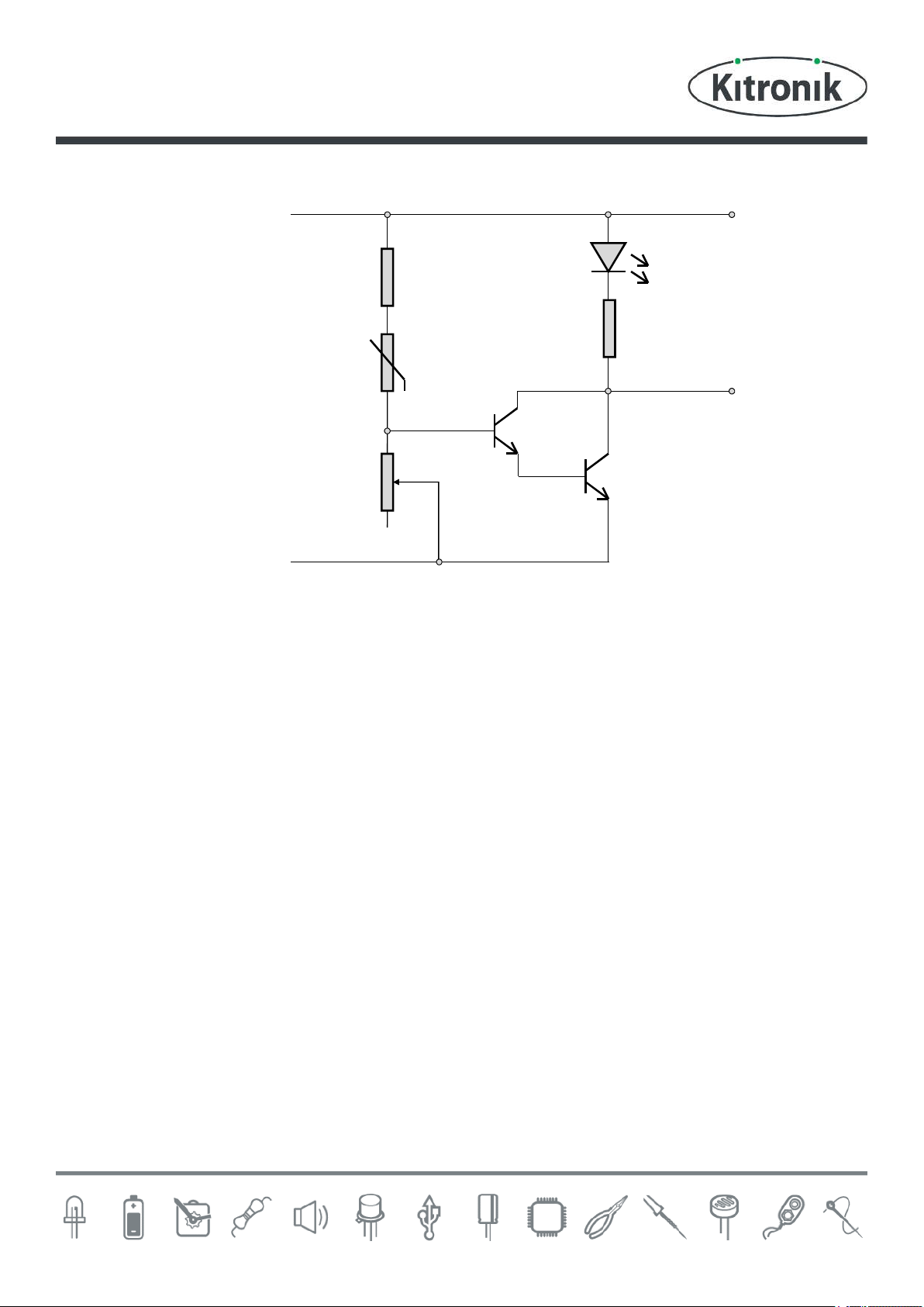
How the heat activated switch works – Cold activated
The circuit operation is very simple. When the input to the transistor Q1, which is fed from the connecting point of
R1 and R2, is greater than 1.4V the output is turned on. The voltage at the join of R1 and R2 is determined by the
ratio of the two resistors. This is known as potential divider.
Voltage at the join of R1 and R2 = The supply Voltage x (R1/(R1+R2))
Normally it requires 0.7V to turn on a transistor but this circuit uses two transistors in a Darlington Pair meaning it
requires 2 x 0.7V = 1.4V to turn on both transistors.
It is also worth noting that the output, when turned on, will be around 0.9V lower than the supply voltage V+. This is
because of the voltage drop across the collector and emitter pins of the Darlington Pair of transistors. Therefore if
the supply voltage is 5V then the output voltage will be around 4.1V.
R4 is present to protect the transistor should the variable resistor be set to zero.
Adjusting the trigger level
The point at which the circuit is triggered is set by the 47KΩ variable resistor. By varying the value of this resistor the
ratio of the resistance of R1 and R2 can be varied to a point where a centre voltage (trip point) of 1.4V is achieved at
the desired light level.
LED (if fitted)
If LED1 and R3 are fitted the LED will light at this point. The value of R3 should be selected for the relevant supply
voltage on LED used. A standard LED would require around 10mA (0.01A) producing a normal brightness. As stated a
5V supply would give 4.1V across LED1 and R3. The LED1 would use 1.9V leaving around 2.2V (4.1V-1.9V) across R3.
Using R = V/I R3 = 2.2 / 0.01 R3 = 220Ω
V+
LED1
R4
220
Transistor
Q2
Transistor
Q1
R1
47K
R2
Thermistor
0V
R3
+
-
Output
Page 6
Heat Activated Switch Essentials
www.kitronik.co.uk/2113
How the heat activated switch works – Heat activated
The circuit operation is very simple. When the input to the transistor Q1, which is fed from the connecting point of
R1 and R2, is greater than 1.4V the output is turned on. The voltage at the join of R1 and R2 is determined by the
ratio of the two resistors. This is known as potential divider.
Voltage at the join of R1 and R2 = The supply Voltage x (R1/(R1+R2))
Normally it requires 0.7V to turn on a transistor but this circuit uses two transistors in a Darlington Pair meaning it
requires 2 x 0.7V = 1.4V to turn on both transistors.
It is also worth noting that the output, when turned on, will be around 0.9V lower than the supply voltage V+. This is
because of the voltage drop across the collector and emitter pins of the Darlington Pair of transistors. Therefore if
the supply voltage is 5V then the output voltage will be around 4.1V.
Note: R4 is only present to protect the transistor in the cold activated version (when the variable resistor is set to
zero).
Adjusting the trigger level
The point at which the circuit is triggered is set by the 47KΩ variable resistor. By varying the value of this resistor the
ratio of the resistance of R1 and R2 can be varied to a point where a centre voltage (trip point) of 1.4V is achieved at
the desired light level.
LED (if fitted)
If LED1 and R3 are fitted the LED will light at this point. The value of R3 should be selected for the relevant supply
voltage on LED used. A standard LED would require around 10mA (0.01A) producing a normal brightness. As stated a
5V supply would give 4.1V across LED1 and R3. The LED1 would use 1.9V leaving around 2.2V (4.1V-1.9V) across R3.
Using R = V/I R3 = 2.2 / 0.01 R3 = 220Ω
V+
LED1
R4
220
Transistor
Q2
Transistor
Q1
R2
47K
0V
R3
+
-
Output
R1
Thermistor
Page 7

Heat Activated Switch Essentials
www.kitronik.co.uk/2113
Applications
Heat activated fan/cooler
By using a temperature activated
board built in the heat activated
option and the addition of motor it
is possible to make a heat
activated fan (shown right). The
fan can be set up to come on at a
desired temperature by adjusting
the variable resistor.
Parts list to build 100 heat activated fans:
Part no. Description Qty
2113 Temperature activated switch 100
2234-25 3 x AA battery cage with clip, pack of 25 4
2238-25 PP3 Battery clip lead, pack of 25 4
2501 Pack of 10 motors 10
2503 Pack of 10 motor clips 10
2201-40 Zinc Chloride AA batteries, box of 40 8
Babies bath over temperature indicator
By using a temperature activated board built in the heat activated option it is possible to make a simple
babies bath too hot indicator. The ‘too hot’ state can be indicated by an LED that light by the addition of
the 150Ω resistor (in R3) and red LED (in LED1).
The thermistor should be mounted on separate flying leads as the PCB should not be immersed in water.
Parts list to build 100 babies bath over temperature indicators:
Part no. Description Qty
2113 Temperature activated switch 10
2234-25 3 x AA battery cage with clip, pack of 25 4
2238-25 PP3 Battery clip lead, pack of 25 4
3003-150R 150ohm resistor, pack of 100 1
3504 Red 5mm LED, pack of 50 2
2201-40 Zinc Chloride AA batteries, box of 40 8
Page 8

Online Information
Two sets of information can be downloaded from the product page where the kit can also be reordered from. The
‘Essential Information’ contains all of the information that you need to get started with the kit and the ‘Teaching
Resources’ contains more information on soldering, components used in the kit, educational schemes of work and so
on and also includes the essentials. Download from:
www.kitronik.co.uk/2113
Every effort has been made to ensure that these notes are correct, however Kitronik accept no responsibility for
issues arising from errors / omissions in the notes.
Kitronik Ltd - Any unauthorised copying / duplication of this booklet or part thereof for purposes except for use
with Kitronik project kits is not allowed without Kitronik’s prior consent.
This kit is designed and manufactured in the UK by Kitronik
 Loading...