

Kitronik FM Radio KIT Essential Information
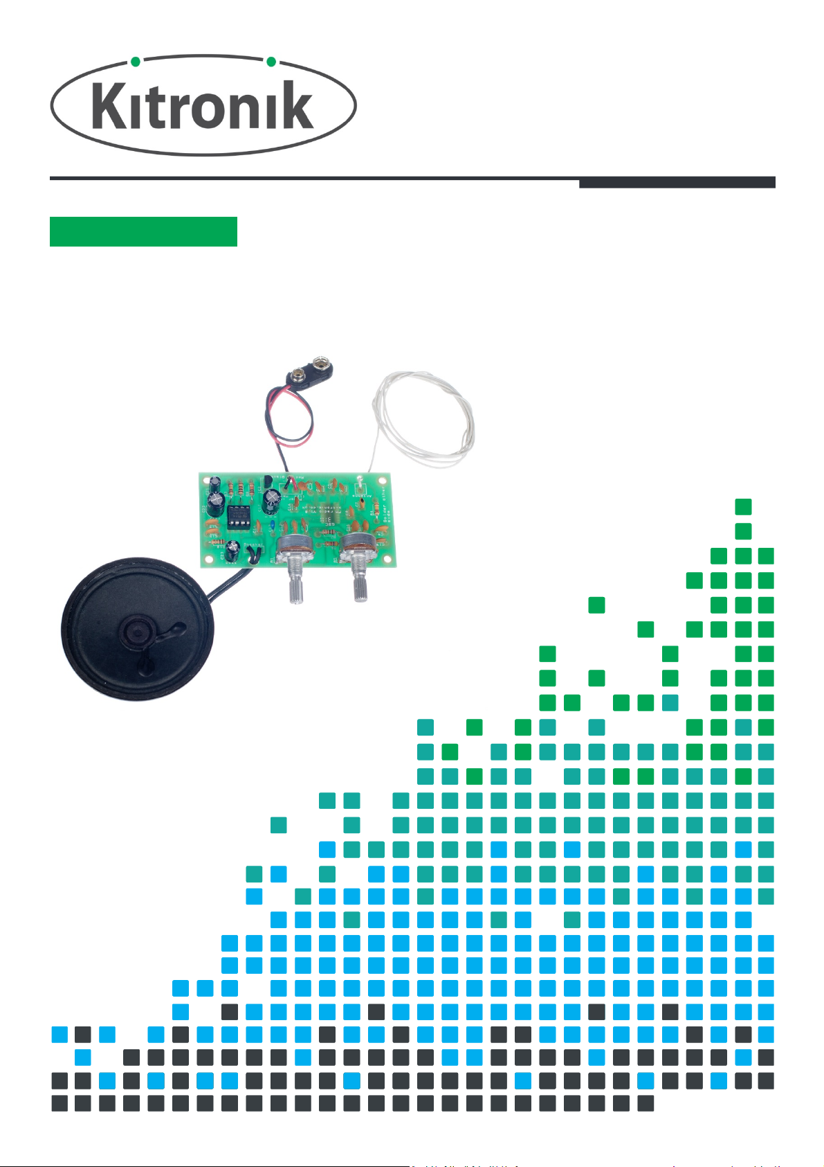
FM RADIO KIT
GET IN TUNE WITH THIS
ESSENTIAL INFORMATION
BUILD INSTRUCTIONS
FINDING
MECHANICAL DETAILS
WORKS
Version 2.
0
CHECKING YOUR PCB & FAULT-
HOW THE KIT
FM Radio Essentials
PCB Ref
Value
Colour Bands
R2 & R8
10K
Brown, black, orange
R3 & R4
100K
Brown, black, yellow
R6
4.7K
Yellow, purple, red
R7
15K
Brown, green,
orange
R9
Brown, black, brown
R10
Brown, black, gold
PCB Ref
Value
Text
C1, C9, C15, C18
100nF
104
C2, C12, C19, C20
10nF
103
C3 & C5
3.3nF
332
C4, C6, C16
180pF
181C739pF
39C82.2nF
222
C10
330pF
331
C11
220pF
221
C13
220nF
224
C14
470pF
471
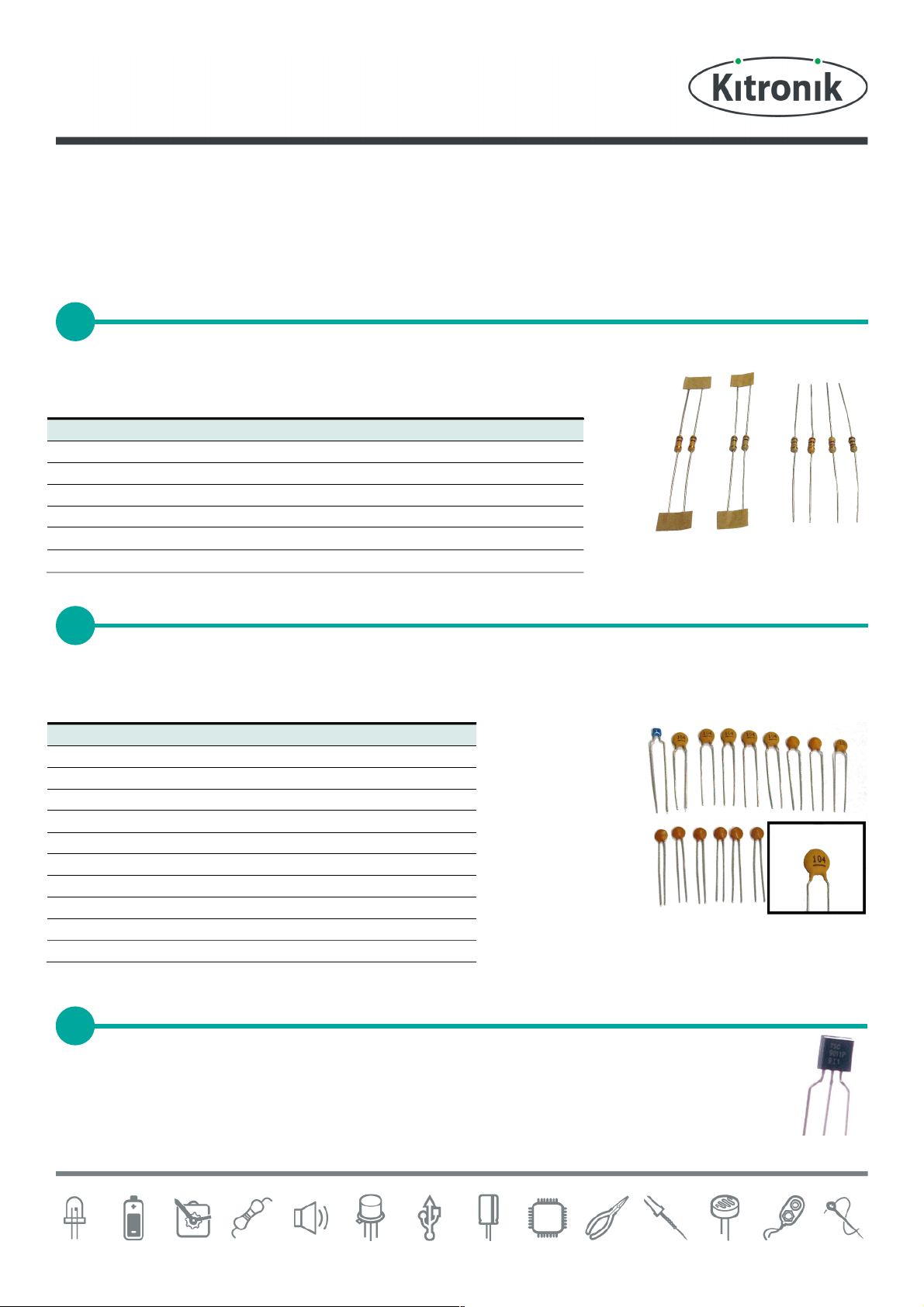
PLACE RESISTORS
1
SOLDER THE CERAMIC DISC CAPACITORS
2
3
www.kitronik.co.uk/2135
Build Instructions
Before you start, take a look at the Printed Circuit Board (PCB). The components go in the side with the writing on
and the solder goes on the side with the tracks and silver pads.
Start with the eight resistors:
The text on the PCB shows where R1, R2 etc go.
Ensure that you put the resistors in the right place.
100
1
The ceramic disc capacitors should be soldered into the board. There are a lot of these so be careful to put them all
in the correct place. The capacitors can be identified by the text printed on them (see close up image below right). It
doesnt matter which way around the capacitor goes into the board.
SOLDER THE VOLTAGE REGULATOR
Solder the voltage regulator (shown right) into the PCB where it is labelled IC2. Make sure that the
shape of the component matches the outline on the PCB.
FM Radio Essentials
PCB Ref
Value
C21
C23
C17 and C22
PCB Ref
Value
R1
10K
R5
100K
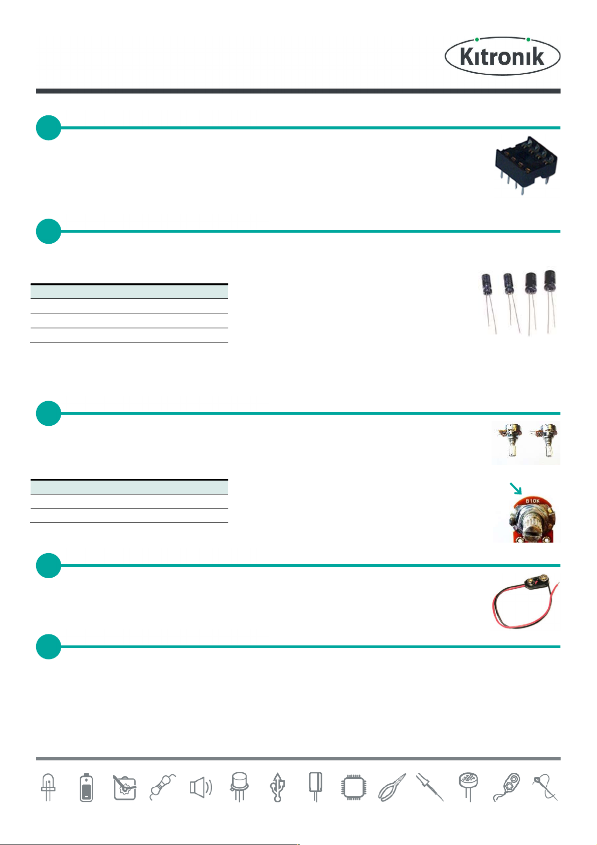
SOLER THE IC HOLDER
4
SOLER THE ELECTROLYTIC CAPACITORS
5
SOLER THE
POTENTIOMETERS
6
ATTACH THE BATTERY CLIP
7
CONNECT THE WIRES
8
www.kitronik.co.uk/2135
Solder the Integrated Circuit (IC) holder into IC3. When putting this into the board, be sure to get it
the right way around. The notch on the IC holder should line up with the notch on the lines marked
on the PCB. Once this has been done insert the 8 pin IC into this socket, making sure that the notch
on the device matches the notch on the IC holder.
Now solder in the four electrolytic capacitors. The capacitors have text printed on the side that indicates their value.
The capacitors are placed as follows.
100F
220F
470F
Make sure that the capacitors are the correct way around. The capacitors have a - sign marked on them, which
should match the same sign on the PCB.
Solder the two potentiometers into the PCB. Each potentiometer has a different value so they have
to be put in the correct place. If you look at the potentiometers, you will see they are labelled with
their value. The shaft of the potentiometer should point away from the PCB.
Value
Solder the PP3 battery clip to the terminals labelled Power In. Connect the red wire to + and the
black wire to - after feeding it through the strain relief hole.
Solder the length of single core wire to the terminal labelled Antenna. You will first have to strip off a piece of the
insulation to expose a short length of the wires core. Before doing this, make sure that you feed it through the strain
relief hole. Once soldered, measure 750mm of wire from the point where the wire is soldered and cut any remainder
off (this will make sure that the antenna is the right length to pick up the correct radio frequencies for the radio).
 Loading...