

Page 1
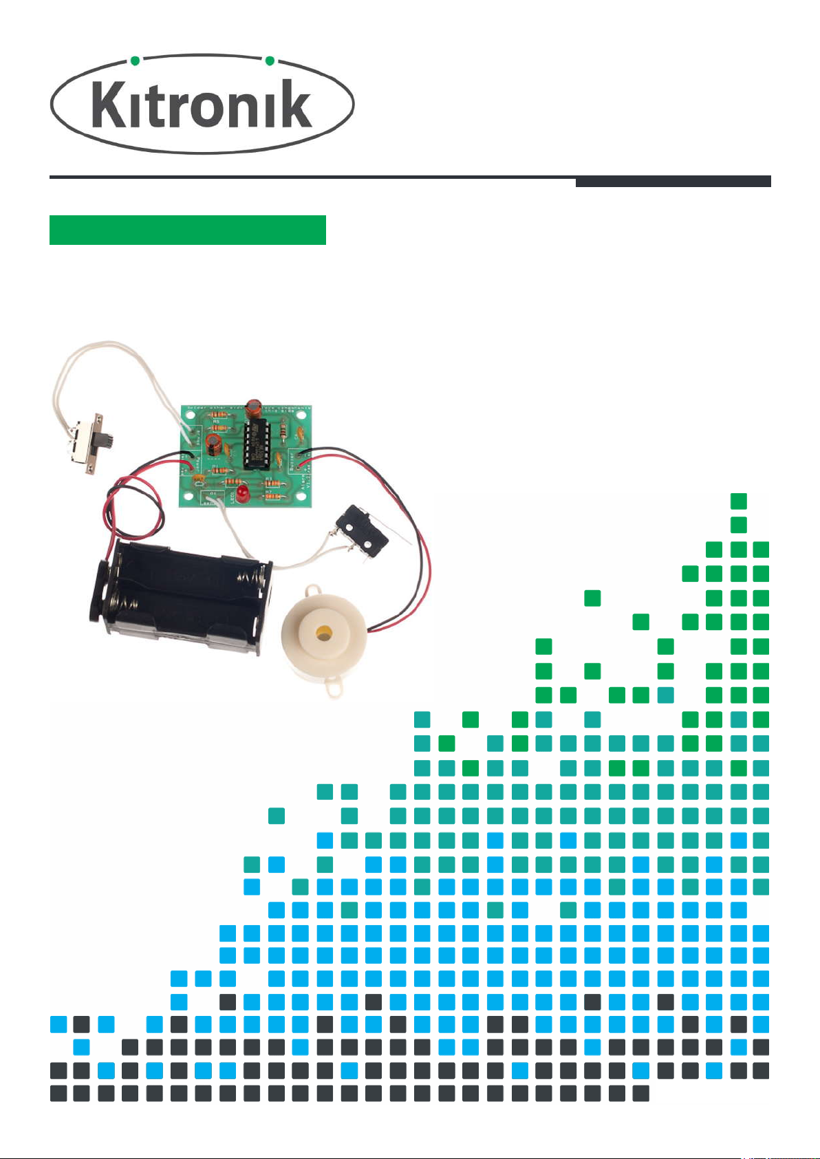
ALARM KIT
WHAT CAN YOU PROTECT WITH THIS
ESSENTIAL INFORMATION
BUILD INSTRUCTIONS
CHECKING YOUR PCB & FAULT-FINDING
MECHANICAL DETAILS
HOW THE KIT WORKS
Version 2.0
Page 2
Alarm Essentials
www.kitronik.co.uk/2101
Build Instructions
Before you start, take a look at the Printed Circuit Board (PCB). The components go in the side with the writing on
and the solder goes on the side with the tracks and silver pads.
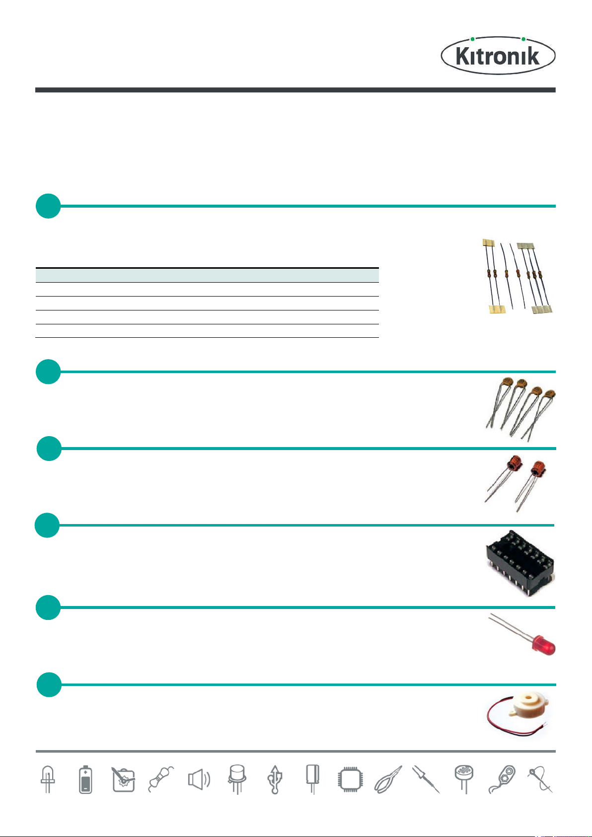
Start with the seven resistors:
The text on the PCB shows where R1, R2 etc go.
Ensure that you put the resistors in the right place.
PCB Ref
Value
Colour Bands
R1, R3 & R5
10KΩ
Brown, black, orange
R2
220K
Ω Red, red, yellow
R7
330Ω
Orange, orange, brown
R4 & R6
1.2M
Ω Brown, red, green
Solder the four ceramic capacitors into C1, C3, C4 and C6. They can go in either position as they
are all the same.
Solder the two electrolytic capacitors into C2 and C5. They can go in either position but it is
important that the ‘–’on the capacitor lines up with the ‘----’ markings on the PCB.
Solder the Integrated Circuit (IC) holder into U1. When putting this into the board, be sure to get
it the right way around. The notch on the IC holder should line up with the notch on the lines
marked on the PCB.
Solder the Light Emitting Diode (LED) into LED1. The alarm won’t work if it doesn’t go in the right
way around. If you look carefully one side of the LED has a flat edge, which must line up with the
flat edge on the lines on the PCB.
The buzzer should be soldered into the ‘buzzer’ terminal. The red wire must go to the ‘+’ terminal
and the black wire must go to the ‘–’ terminal.
PLACE RESISTORS
1
SOLDER THE CERAMIC CAPACITORS
2
SOLDER THE ELECTROLYTIC
CAPACITORS
3
SOLDER THE IC HOLDER
4
SOLDER THE LED
5
SOLDER THE BUZZER
6
Page 3
Alarm Essentials
www.kitronik.co.uk/2101
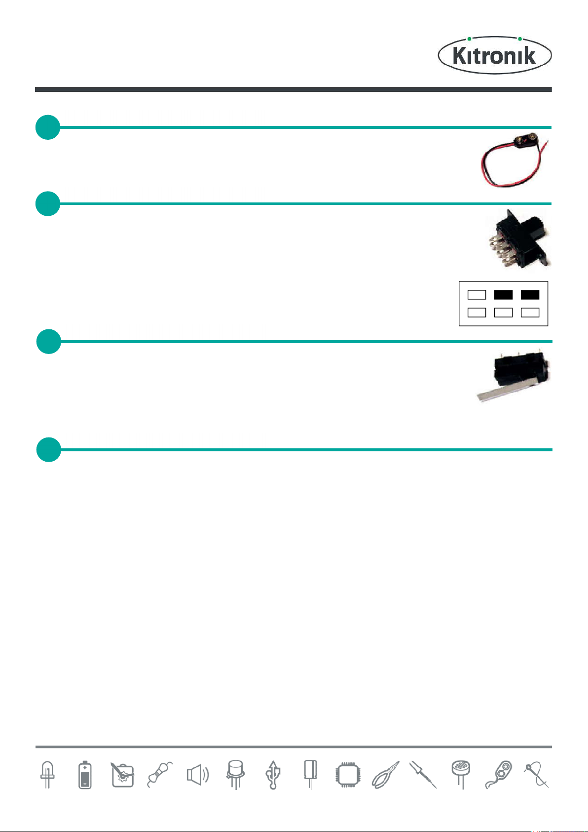
The battery connector should be soldered into the ‘Power’ terminal. The red wire must go to the
‘+’ terminal and the black wire must go to the ‘–’ terminal.
Cut and strip two short lengths of wire. Solder these to an edge and the centre terminal on the
same row of pins on the switch. The terminals that should be used are shown in black on the
drawing, below. Now solder the other end of the wires to the PCB where it is marked ‘armed’. It
does not matter which way around the two wires go.
Look carefully at the sensor switch and you will see that it is marked COM (common), NO
(normally open) and NC (normally closed). Cut and strip two short lengths of wire. Solder these to
the COM and the NO terminals on the switch and solder the other end of the wire to the PCB
connection marked Q1 (sensor).
The IC can be put into the holder ensuring the notch on the chip lines up with the notch on the holder.
FIT THE BATTERY CONNECTOR
7
SOLDER THE ARM / DISARM SWITCH
8
SOLDER DETECTION SWITCH
9
PLACE THE IC INTO HOLDER
10
Page 4

Alarm Essentials
www.kitronik.co.uk/2101
Checking Your Alarm PCB
Check the following before you insert the batteries:
Check the bottom of the board to ensure that:
All holes (except the 4 large 3mm holes) are filled with the lead of a component.
All these leads are soldered.
Pins next to each other are not soldered together.
Check the top of the board to ensure that:
The notch on the IC and the IC holder are in the same orientation as the markings on the Printed Circuit
Board.
All the resistors are in the right place.
The red / black wires on both the power connector and buzzer are the right way around.
The LED is in the right way around.
Both of the electrolytic capacitors have the ‘----’ marking on the PCB lined up with the ‘-’ on the capacitor.
Testing the PCB
When the batteries are connected, either or both the disarm LED / the alarm sounder may start.
To stop this, put the alarm into the disarmed state (push the slide switch so that it is at the end where the
wires are connected).
Now move the arm switch into the arm state (slide the switch the other way).
Close the door switch; the LED should remain off.
Open the switch and the LED should light, indicating that the alarm should be disarmed.
After around 20 – 25 seconds the alarm should sound.
If your circuit does not function as described, use the fault finding flow chart to resolve the issue.
Using the Alarm
To arm / disarm the system use the arm switch.
When exiting the alarmed area, move the arm switch to the arm position.
Close the door behind you.
Upon entering the alarmed area you have 20 –25 seconds in which to disarm the alarm.
The LED will light to indicate that the alarm needs to be disarmed.
Disarm it by moving the arm switch into the disarm position.
Should the alarm not be disarmed in the given time, the buzzer will sound (this will continue for 2 minutes or
until the alarm is disarmed).
Page 5

Alarm Essentials
www.kitronik.co.uk/2101
Fault Finding
Does the
LED go on or
the buzzer
sound?
No
Yes
Yes
Check
• The batteries are good and in the right
way around
• The power clip is in the right place and
connected the right way around and
soldered
• For a short on the arm switch
• For a dry joint on R5 or R6
• U1 pin 5 for dry joints
• U1 pins 4 / 10 for a short
Fault finding flow chart
Start
With the alarm system in the armed
state and the door sensor open.
Power the board up
No
Go to page 2
Close & open the door
sensor
Does the
LED go on or
the buzzer
sound?
Wait for the LED to go out
Then disarm the system
Has the
LED gone off
and the buzzer
stopped?
The LED
stays on
The buzzer
stays on
What is
left on?
Both the LED and
buzzer stay on
No
Check
• R2 for a dry joint
• U1 for a short between pins 6 & 7
• U1 pin 2 for a dry joint
• C4 for a short
Check
• U1 pin 7 for a dry joint
• U1 short between pin 8 & 9
Yes
page 1
Check
For a dry joint on the arm switch and that
the correct terminals have been used on the
switch
Page 6

Alarm Essentials
www.kitronik.co.uk/2101
Yes
Stop
No
Does the
LED light?
Did the
buzzer
sound?
Wait for the LED
to go out
Yes
No
Check
• The buzzer for dry joints
and it is connected the right
way around
• C4 & C5 for dry joints
• U1 pins 8, 9 & 14 for dry
joints
• U1 short between 11 & 12
or 13 & 14
Start
Continued from page 1
Arm the system,
close & open the door
Fault finding flow chart
page 2
Check
• The LED is the right
way around, for dry
joints and shorts
• R7 is the right value
and for dry joints
Check
• U1 pin 6 for a dry joint
• R1 & R6 for dry joints
Does the
buzzer sound
after a
while?
Yes
Check
• C2 for a dry joint
• U1 for a short
between pins 2 & 3
Was the
delay the right
length?
Entry delay shorter
Is R2 the right value
Is there a dry joint on U1 pin 4
Entry delay longer
Is R2 the right value
Is there a short on C1
Alarm shorter
Is R4 the right value
Is there a dry joint on U1 pin 10
Alarm longer / indefinite
Is R4 the right value
Is C5 shorted
Is there a dry joint on R3 or R4
Is there a dry joint on U1 pin 12
Does it
work a 2nd
time?
Yes
Yes
No
No
Check
• The door contact for dry
joints
• U1 pin 1 & 13 for dry joints
No
It is instant
Page 7

Alarm Essentials
www.kitronik.co.uk/2101
Designing the Enclosure
When you design the enclosure, you will need to consider:
The size of the PCB (right).
Where the detector switch will be (below right).
Where the arming switch will be (below left).
Where the buzzer will be mounted (below centre).
Where the 5mm LED indicating the alarm needs disarming is to be
mounted (shown on PCB dimensions image right).
Access to the batteries to allow them to be changed (bottom
right).
Technical drawings of all of these items are illustrated on this page, which should help you design your enclosure.
All dimensions are in mm.
Mounting the PCB to the
enclosure
The drawing to the left
shows how a hex spacer
can be used with two bolts
to fix the PCB to the
enclosure.
Your PCB has four
mounting holes designed to
take M3 bolts.
14
32
37
45.5
14
32
37
45.5
10
9.5
20
3
2
2
.
5
3
10
9.5
20
3
2
2
.
5
2
2
.
5
3
Page 8

Alarm Essentials
www.kitronik.co.uk/2101
How the Alarm Works
The alarm is based around the 556 Timer. This is simply two 555 Timers in the same chip.
The 555 Timer is a versatile IC (Integrated Circuit) and can be used to form many circuits. One of these circuits is a
monostable timer. This circuit produces a single pulse when triggered. This means that the Out pin is high and causes
the LED to light.
To trigger the circuit the Trig input must go from a high to a low voltage. When the door switch is closed, the Trig
input is high and the circuit is not triggered. When it opens, the Trig input is taken low and the output pulse starts.
The duration of the pulse generated is determined by the RC constant formed by the resistor and capacitor
connected to the Threshold input. When the trigger line goes low, the Discharge pin is used to start the 100µF cap
charging. When it is charged the Out pin changes from high to low. The first 555 Timer is used to provide the entry
delay, which is the time you have to disarm the alarm before it triggers. When this times out (100µF x 220KΩ = 22
seconds) the output goes low and causes the second 555 Timer circuit to start and the LED to go out. The second
timer turns the buzzer on for two minutes (100µF x 1.2MΩ =120 seconds).
When the Arm switch is closed, the circuit is held in reset and the alarm is disarmed (off). When the switch is open,
the 10KΩ resistor connected to both Reset inputs pulls them to 6V and the circuit is active.
Irrespective of the state of the alarm the 556 Timer IC uses around 10 mA current. This means that a typical battery
life will be about one week.
Page 9

Online Information
Two sets of information can be downloaded from the product page where the kit can also be reordered from. The
‘Essential Information’ contains all of the information that you need to get started with the kit and the ‘Teaching
Resources’ contains more information on soldering, components used in the kit, educational schemes of work and so
on and also includes the essentials. Download from:
www.kitronik.co.uk/2101
Every effort has been made to ensure that these notes are correct, however Kitronik accept no responsibility for
issues arising from errors / omissions in the notes.
Kitronik Ltd - Any unauthorised copying / duplication of this booklet or part thereof for purposes except for use
with Kitronik project kits is not allowed without Kitronik’s prior consent.
This kit is designed and manufactured in the UK by Kitronik
 Loading...