

Kitronik 2154, MP3 Mono Amplifier V2.0 Essential Information

CREATE YOUR OWN SPEAKER DOCK WITH THIS
ESSENTIAL INFORMATION
BUILD INSTRUCTIONS
FINDING
MECHANICAL DETAILS
WORKS
Version 2.
2
MONO AMPLIFIER KIT
CHECKING YOUR PCB & FAULT-
HOW THE KIT
Mono Amplifier Essentials
PCB Ref
Value
Colour Bands
R1 4.7k
Yellow, purple, red
R2 & R3
10Ω Brown, black,
black
PLACE RESISTORS
1
2
SOLDER THE CERAMIC DISC CAPACITORS
3
SOLDER THE
ELECTROLYTIC CAPACITORS
4
CONNECT THE
POWER WIRES
5
www.kitronik.co.uk/2154
Build Instructions
Before you start, take a look at the Printed Circuit Board (PCB). The components go in the side with the writing on
and the solder goes on the side with the tracks and silver pads.
Start with the three resistors:
The text on the PCB shows where R1, R2 etc go.
Ensure that you put the resistors in the right place.
SOLDER THE IC HOLDER
Solder the Integrated Circuit (IC) holder into IC1. When putting this into the board, be sure to get
it the right way around. The notch on the IC holder should line up with the notch on the lines
marked on the PCB.
There is one ceramic disc capacitor which should be soldered in to C1 on the PCB. The capacitor should
be marked ‘473’. It does not matter which way around it goes.
The other two capacitors are electrolytic capacitors, they are both marked 100uF. Place these two
capacitors in to the board where it is labelled C2 and C3. Make sure the device is the correct way
around. The capacitors have a ‘-’ sign marked on them which should match the same sign on the
PCB.
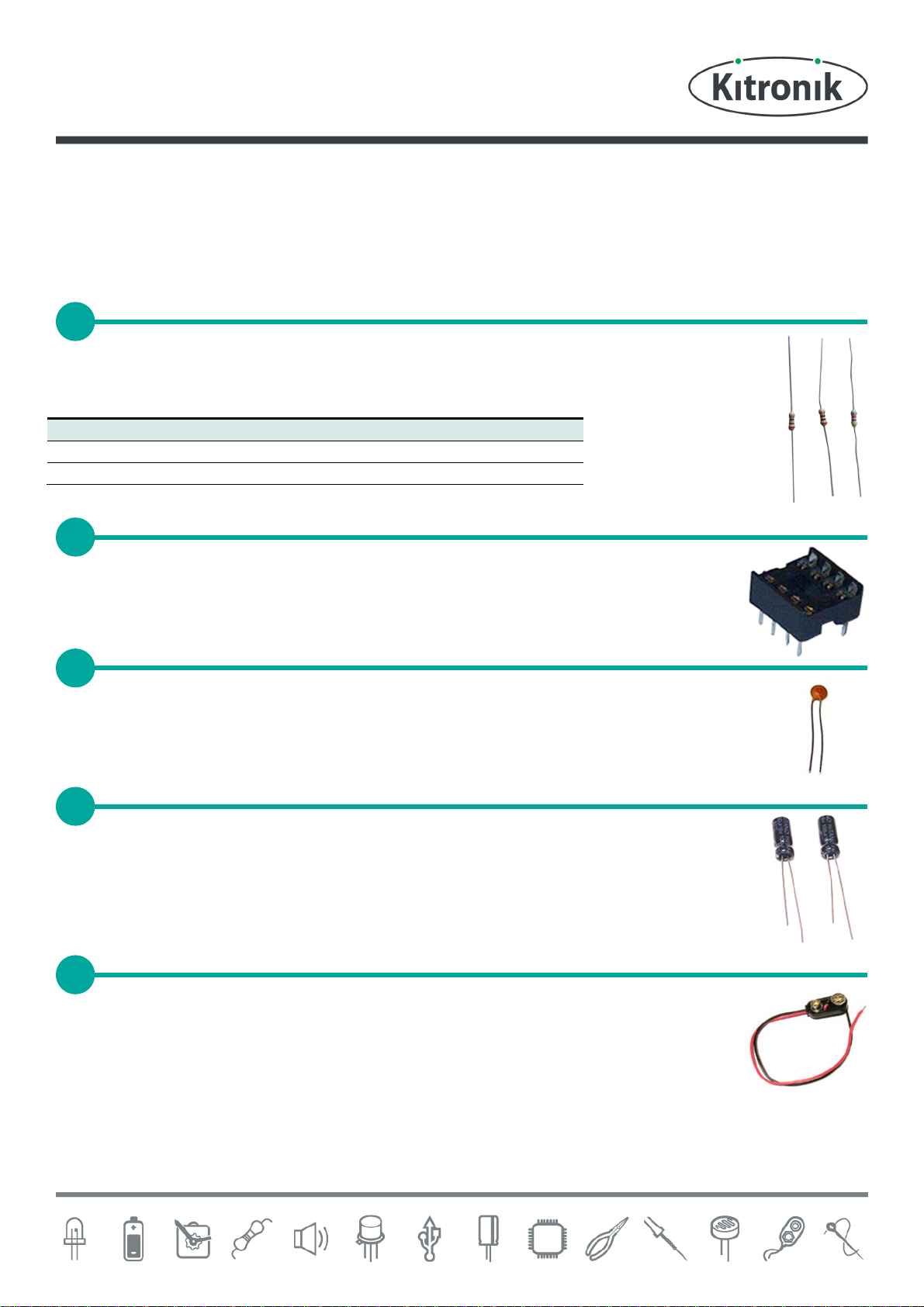
The PP3 battery clip (shown right) should be attached to the power connection. This is the
central two pads and can be identified by the word “Power” on the PCB. Connect the red wire to
‘+’ and the black wire to ‘-’. The wires should be fed through the strain relief hole before being
soldered into place.
Mono Amplifier Essentials
CONNECT THE JACK LEAD
7
CUT THE JACK LEAD
6
CONNECT THE SPEAKER
8
INSERTING THE IC INTO THE HOLDER
9
www.kitronik.co.uk/2154
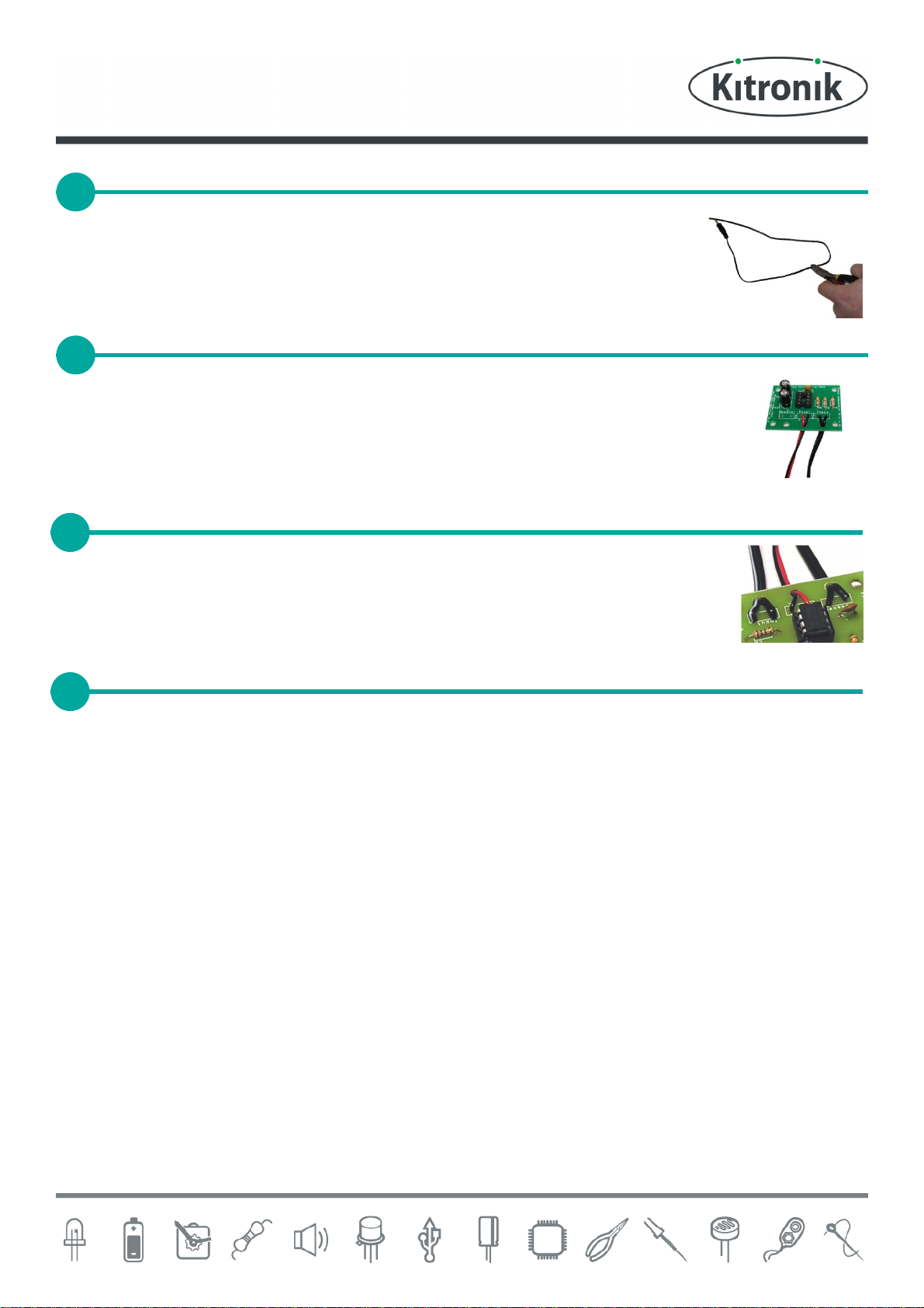
The kit is supplied with ½ a metre of twin cable with a 3.5mm Jack connector on one end.
This cable will be used to connect both the speaker and the MP3 player. You will need to
cut a length from the end that does not have the Jack connector on, which will be used to
connect the speaker in a later step. Make sure that you leave enough cable on the end with
the jack so that you have a long enough lead to connect your MP3 player!
Strip the insulation from the other end of the cable that has the Jack plug on. Run some solder
onto the exposed wire and trim the wire so that only 2 or 3mm of tinned wire is left. Solder these
wires into the board where it is labelled ‘Input’. It doesn’t matter which of the pair of wires goes
into each of the two pads. The wires should be fed through the strain relief hole before being
soldered into place.
Take the piece of wire that you previously cut from the jack lead and strip the ends of the wire.
Solder one end to the two terminals on the speaker and the other end to the board connection
marked ‘Speaker’. It does not matter which way around these connections go. Again the wires
should be fed through the strain relief hole before being soldered into place.
The IC can now be put into the holder, ensuring the notch on the chip lines up with the notch on the holder. Your
amplifier is ready for use. You can use the volume control on your MP3 player to control how loud the amplifier is.
Just make sure that it’s mid volume when you test the amplifier.
Checking Your Amplifier PCB
Carefully check the following before you insert the batteries:
Audio equipment may become damaged if connected to an incorrectly built amplifier.
Check the bottom of the board to ensure that:
• All holes (except the 4 large (3 mm) holes in the corners) are filled with the lead of a component.
• All these leads are soldered.
• Pins next to each other are not soldered together.
Check the top of the board to ensure that:
• The three wires are connected to the right place.
• The ‘-’ on the capacitors match the same marks on the PCB.
• The colour bands on R1 are yellow, purple, red & R2 & R3 are brown, black, black.
• The battery clip red and black wires match the red & black text on the PCB.
• The notch on the IC is next to the power connection.
 Loading...