

KITO Harrington RYU030A25HDD, Harrington RY Series, Harrington RYU050B25HDD, Harrington RYU050B33HDD, Harrington RYU030A33HDD Owner's Manual
EFFECTIVE: May 8, 2019
ELECTRIC
WIRE ROPE
HOIST and TROLLEY
RY SERIES
3 Ton and 5 Ton Capacity
Hoist Code and Serial Number
This equipment sh ould not be i nstal le d, op erat ed or
maintained by a ny pers on w ho has n ot re ad a nd
understood all t he cont ents o f this manu al. Fail ur e to r ead
and comply w ith th e co nte nts of thi s m anual c an res ul t in
serious bodily inj ury or dea th, and/ or pr op erty d amag e.
© Harrington Hoists, Inc.
All Rights Reserved

Table of Contents
Section Page Number
1.0 Important Information and Warnings…………………………………………….……………………. 4
1.1 Terms and Summary
1.2 Warning Tags and Labels
2.0 Technical Information …………………………….…………………………………………………… 10
2.1 Specifications
2.2 Dimensions
2.3 Part Names
3.0 Pre-operational Procedures……………………………………………………………………….….. 16
3.1 General Information
3.2 Handling
3.3 Mounting Location
3.4 Assembly, Adjustments and Mounting
3.5 Block Operated Limit Switch (BLS) Adjustment
3.6 Electrical Connections
3.7 Pendant Installation
3.8 Hoist Variable Frequency Drive (VFD) Setup
3.9 Light-Load High Speed Function
3.10 Hoist Load Limiter (LL) Adjustment
3.11 Trolley Variable Frequency Drive (VFD) Setup
3.12 Hoist Upper and Lower Limit Switch (ULLS) Setup
3.13 Pre-operational Checks and Trial Operation
4.0 Operation……………………………………………………………………………………………….. 44
4.1 Introduction
4.2 Shall’s and Shall Not’s for Operation
4.3 Hoist and Trolley Controls
2

Section Page Numbe r
5.0 Inspection……………………………………………………………………………………………….. 48
5.1 General
5.2 Inspection Classification
5.3 Frequent Inspection
5.4 Periodic Inspection
5.5 Occasionally Used Hoists and Trolleys
5.6 Inspection Records
5.7 Inspection Methods and Criteria
6.0 Maintenance & Handling………………………………………………………………………….…… 61
6.1 Count/Hour Meter
6.2 Lubrication
6.3 Lubrication – Hoist Gearbox
6.4 Hoist Motor Brake
6.5 Trolley Brake Adjustment
6.6 Wire Rope, Reeving and Adjustment
6.7 Storage
6.8 Outdoor Installation
6.9 Operational Environment
7.0 Troubleshooting …………………………………..…………………………………………………… 80
7.1 General Troubleshooting
7.2 VFD Troubleshooting
7.3 VFD Error Rest and Restart
7.4
VFD Monitor ing , Err or Tr ace and Er ror H ist ory
8.0 Warranty…..……………………………………………………………………………………………101
9.0 Parts List..…………………………………...…………………………………………………………102
3

1.0 Important Informat ion and W arnings
1.1 Terms and Summary
This manual provides impor tant infor mation for personnel involved with the installation, operation and maintenance
of this product. Although you may be familiar with this or similar equipment, it is strongly recommended that you read
this manual before installing, operating or maintaining the product.
Danger, Warning, Cauti on and Notic e - Throughout this manual there are steps and procedures that can present
hazardous situations. The following signal words are used to identify the degree or level of hazard seriousness.
Danger indicates an imminently hazardous situation which, if not avoided, will result in death or
serious injury, and property damage.
Warning indicates an imminently hazardous situation which, if not avoided, could result in death or
serious injury, and property damage.
Caution indicates a potentially hazardous situation which, if not avoided, may result minor or
moderate injury or property damage.
Notice is used to notify people of installation, operation, or maintenance information which is
important but not directly hazard-related.
INTENDED USE OF HOIST/TROLLEY HOIST and Owner’s Manual
“The RY hoists and trolley hoists are intended only for vertical lifting service of freely suspended, unguided loads. In
addition to lifting service of freely suspended, unguided loads, RY trolley hoists are to be used to traverse these loads
on a single girder beam.
The RY hoist and trolley hoists are not intended to lift greater than rated loads, lift, support or transport people nor lift
loads over people.
The RY hoist and trolley hoists are intended to be operated by persons who have read and understood the operation
section of the RY owner’s manual, all warnings and are familiar with the RY hoist/trolley hoist controls.”
4

These general instructions deal with the normal installation, operation, and maintenance situations encountered with
the equipment described herein. The instructions should not be interpreted to anticipate every possible contingency
or to anticipate the final system, crane, or configuration that uses this equipment. For systems using the equipment
covered by this manual, the supplier and owner of the system are responsible for the system’s compliance with all
applicable industry standards, and with all applicable federal, state and local regulations/codes.
This manual includes instructions and parts information for the RY trolley hoist. Therefore, all instructions and parts
information may not apply to any one type or size of specific trolley hoist. Disregard those portions of the instructions
that do not apply.
Record your trolley hoist’s Product Code and Serial Number on the front cover of this manual for identification and
future reference to avoid referring to the wrong manual for information or instructions on installation, operation,
inspection, maintenance, or parts.
Use only Harrington authorized replacement parts in the service and maintenance of this trolley.
5

Equipment described herein is not designed for and MUST NOT be used for lifting, supporting, or transporting people,
or for lifting or supporting loads over people.
Equipment described herein should not be used in conjunction with other equipment unless necessary and/or
required safety devices applicable to the system, crane, or application are installed by the system designer, system
manufacturer, crane manufacturer, installer, or user.
Modifications to upgrade, rerate, or otherwise alter this equipment shall be authorized only by the original equipment
manufacturer.
Equipment described herein may be used in the design and manufacture of cranes or monorails. Additional
equipment or devices may be required for the crane and monorail to comply with applicable crane design and safety
standards. The crane designer, crane manufacturer, or user is responsible to furnish these additional items for
compliance. Refer to ANSI/ASME B30.17, “Safety Standard for Top-Running Single Girder Cranes”; ANSI/ASME
B30.2 “Safety Standard for Top-Running Double-Girder Cranes”; and ANSI/ASME B30.11 “Safety Standard for
Underhung Cranes and Monorails”.
Hoists, trolleys and cranes, used to handle hot molten material may require additional equipment or devices. Refer to
ANSI Z241.2, “Safety Requirements for Melting and Pouring of Metals in the Metalcasting Industry”.
Electrical equipment described herein is designed and built in compliance with Harrington's interpretation of
ANSI/NFPA 70, “National Electrical Code”. The system designer, system manufacturer, crane designer, crane
manufacturer, installer, or user is responsible to assure that the installation and associated wiring of these electrical
components is in compliance with ANSI/NFPA 70, and all applicable Federal, State and Local Codes.
Failure to read and comply with any one of the limitations noted herein can result in serious bodily injury or death,
and/or property damage.
6
HAZARDOUS VOLTAGES ARE PRESENT IN THE CONTROL BOX, OTHER ELECTRICAL COMPONENTS,
AND CONNECTIONS BETWEEN THESE COMPONENTS.
Before performing ANY mechanical or electrical maintenance on the equipment, de-energize (disconnect) the main
switch supplying power to the equipment; and lock and tag the main switch in the de-energized position. Refer to
ANSI Z244.1, “Personnel Protection – Lockout/Tagout of Energy Sources”.
Hoist incorporates a VFD as well as a Capacitor. Therefore, DO NOT perform ANY mechanical or
electrical maintenance within 5 minu tes of powering down to allow time for the capacitor inside the
VFD to discharge. DO NOT perform any voltage or in sulation resistance tests with a meg ohmmeter
when the VFD is connected to the electr ical circuit.
Only trained and competent personnel should inspect and repair this equipment.
The VFD is designed in Harrington Hoists exclusive specifications. Do NOT use other than Harrington Hoist,
Inc. – authorized VFD.
• Do NOT modify the VFD.
• Do NOT change the wiring.
• Do NOT perform a withstand voltage test or measurement of insulating resistance with the VFD connected.
• Do NOT shut down the power supply during oper at io n.
• Do NOT connect the power supply to the output side of the VFD.
Before performing parameter change or maintenance of the VFD, read this owner’s manual and observe the
information contained herein.
Parameter change and maintenance must be performed by a competent person with experience and expertise
of handling the rope hoist and VFD.
The product is energized during a parameter change or maintenance of the VFD. Do NOT remove the cover of
the VFD. Do NOT
Each hoist heats up during operation. Do NOT maintain and inspect the electrical components for 30 minutes
after a stop of operation.
When handling the VFD, provide protection for Electrostatic Discharge (ESD).
Do NOT perform maintenance and inspection of peripheral parts (excluding the VFD) within 5 minutes after de-
energizing.
Failure to comply with the instructions may lead to an electric shock, burns, malfunction, breakdown or VFD
damage, and even may cause serious or even fatal injury.
touch the circuit board or electrical components around the VFD.
7

It is the responsibility of the owner/user to install, inspect, test, maintain, and operate a trolley hoist in accordance with
ANSI/ASME B30.16, “Safety Standard for Overhead Hoists”, OSHA Regulations and ANSI/NFPA 70, "National
Electric Code". If the trolley hoist is installed as part of a total lifting system, such as an overhead crane or monorail, it
is also the responsibility of the owner/user to comply with the applicable ANSI/ASME B30 volume that addresses that
type of equipment.
It is the responsibility of the owner/user to have all personnel that will install, inspect, test, maintain, and operate a
trolley hoist read the contents of this manual and applicable portions of ANSI/ASME B30.16, “Safety Standard for
Overhead Hoists”, OSHA Regulations and ANSI/NFPA 70, “National Electric Code”. If the trolley is installed as part of
a total lifting system, such as an overhead crane, the applicable ANSI/ASME B30 volume that addresses that type of
equipment must also be read by all personnel.
If the trolley hoist owner/user requires additional information, or if any information in the manual is not clear, contact
Harrington or the distributor of the trolley. Do NOT
this information is fully understood.
install, inspect, test, maintain, or operate this trolley hoist unless
A regular schedule of inspection of the trolley hoist in accordance with the requirements of ANSI/ASME B30.16 should
be established and records maintained.
8
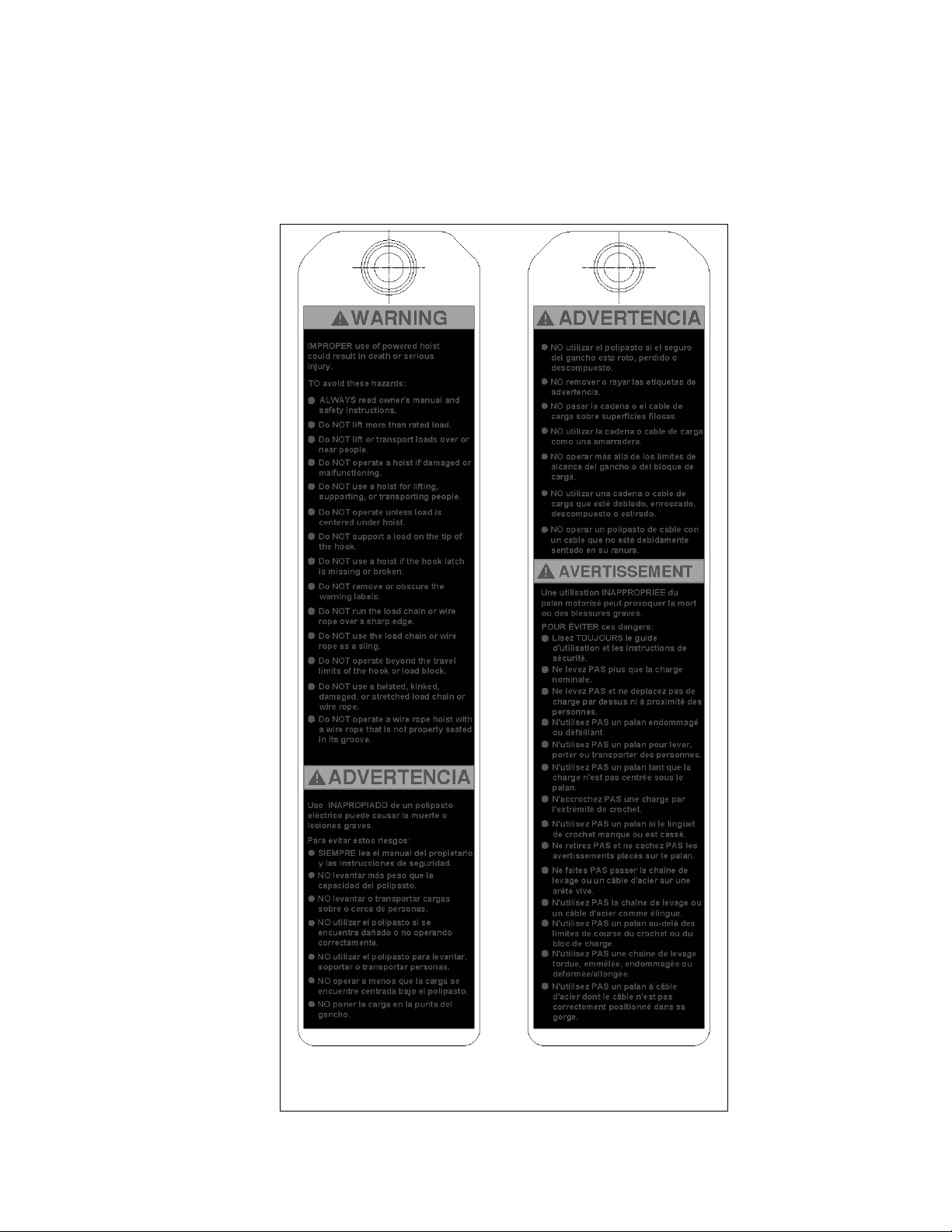
1.2 Warning Tag and Labels
The warning tag illustrated below in Figure 1-1 is supp lie d with each RY hoist and trolley hoist shipped from the
factory. If the tag is not attached to the pendant cord for your hoist/trolley, order a tag from your dealer and install
it. Read and obey all warnings attached to this Hoist. Tag is not shown actual size.
front back
Figure 1-1 Warning Tag Attached to Hoist
9

Trolley Hoist Capacity Ratin g
3T & 5T
ASME
H4
ISO
M5
FEM
2m
Ratio of Inte rmittence
60 (40/20)
Start Ups per Hour
240
Cycles per Hour
40
Ratio of Inte rmittence
30 (20/10)
Start Ups per Hour
180
Cycles per Hour
30
1/3 (33.3% of total number of
start-ups per hour)
2/3 (66. 7% of total number of
start-ups per hour)
1/3 (33.3% of the average
daily running time)
Running Time at Main Speed (min.)
30
Running Time at Low Speed (min.)
3.5
Maximum number of starts-ups per hour
10
Motor Ins ulation C lass – Hoist and Trolley.
F type
Lifting Brake Capacity
150% capacity or more
2.0 Technical Informat ion
NOTE: Throughout this section the symbol ““ is used as a place holder for the trolley hoist voltage. The
available trolley hoist voltages are listed in Section 2.1.1 that follows.
2.1 Specifications
2.1.1 Product Code:
2.1.2 Operating Conditions and Environment
Temperature Range: -4° to +104°F (-20° to +40°C)
Humidity: 90% RH or less (no condensation)
Electrical Enclosure Rating: IP55
Motors and Pendant: IP65
Speed: Dual – Variable Frequency Drive (VFD)
Supply Voltage: 208V- 230V or 415-460V-3ph-50/60Hz
Control Voltage: 110V-1ph-60Hz (Optional: 24V-1ph-60Hz)
Noise Rating: less than 85 dba at full speed (A scale: measured 1 meter away
from electric wire rope hoist)
Table 2-1 Hoist and Trolley Duty Ratings
Service Group
Hoist
Intermittent Use
Trolley
Start Ups per
Hour
Dual Speed
Motors
Daily Run Time
Main Speed
Low Speed
Main Speed
Low Speed
2/3 (66.7% of the average
daily running time)
Temporary Use
10

Reeving
Lifting Motor
1
Output
2
Flange Range
B
Table 2-2 Ultra-Low Headroom Trolley Hoists Hoist Specifications
Capacity
(Ton)
3
5
1) Low and high speeds are adjustable
2) Current values based on 250 kVA power supply
Product Code
RYU030A25HDD 25
RYU030A33HDD 33
RYU050B25HDD 25
RYU050B33HDD 33
Lift
(ft.)
Table 2-3 Ultra-Low Headroom Trolley Hoists Trolley Specifications
Rope
(Parts/
reeving)
4/1 9 26/4.3 39
Dia.
(mm)
Lifting Speed
(ft/min)
Initial
High/Low
Speed
No
Load
High
Speed
3 Phase - 50/60Hz
Rated Current
(amps)
(Hp)
6.7 24.7 12.1
10.7 36.5 18.3
@208-230V/
60Hz
@415- 460V/
60Hz
Capacity
(Ton)
3
5
2) Current values based on 250 kVA power supply
Product Code
RYU030A25HDD
RYU030A33HDD
RYU050B25HDD
RYU050B33HDD
4.92-13.78
13.79-19.68 971
4.92-13.78 1048
13.79-19.68 1059
4.92-13.78 993
13.79-19.68 1004
4.92-13.78 1092
13.79-19.68 1103
(in)
Travers ing M otor
3 Phase – 50/60Hz
Traversing
Speed2
(ft/min)
Initial
High/Low
Speed
66/11 0.54 2.1 1.4
Output
(Hp)
Rated Current2
(amps)
@208-230V/
60Hz
@415-460V/
Net Weight
(lbs)
60Hz
960
11
Flange
(in)
4.92-
13.78
32.4-
23.6
13.79-
19.68
29.5-
23.6
4.92-
13.78
32.4-
23.6
13.79-
19.68
29.5-
23.6
13.79-
19.68
29.5-
23.6
13.79-
19.68
29.5-
23.6
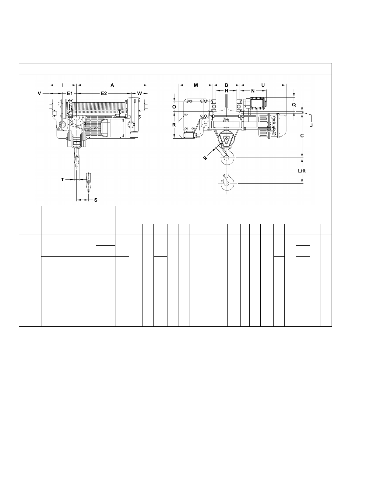
2.2 Dimensions
Table 2-4 Ultra-Low Headroom Trolley Hoist Dimensions
Capacity
(Tons)
3
5
Product Code
RYU030A25HDD 25
RYU030A33HDD
RYU050B25HDD 25
RYU050B33HDD
Lift
(ft)
33
33
14.1
14.1
Dimensions (in)
1.2
or
17.4 13.5 4.9 7.3 13.7
less
1.2
or
17.4 13.5 4.9 7.3 13.7
less
Range
B
A C E1 E2 g H I J M N O Q R S T U V W
36.3
22.8 7.3
44.7 36.1 8.4
4.92-
13.78
36.3
4.92-
13.78
23.2 7.3
44.7 36.1 8.4
27.8
27.8
1.7
1.8
B-
3.1
B-
3.1
6.3
6.3
2.1
2.5
32.4-
23.6
32.4-
23.6
6.7 8.5
6.7 8.5
12
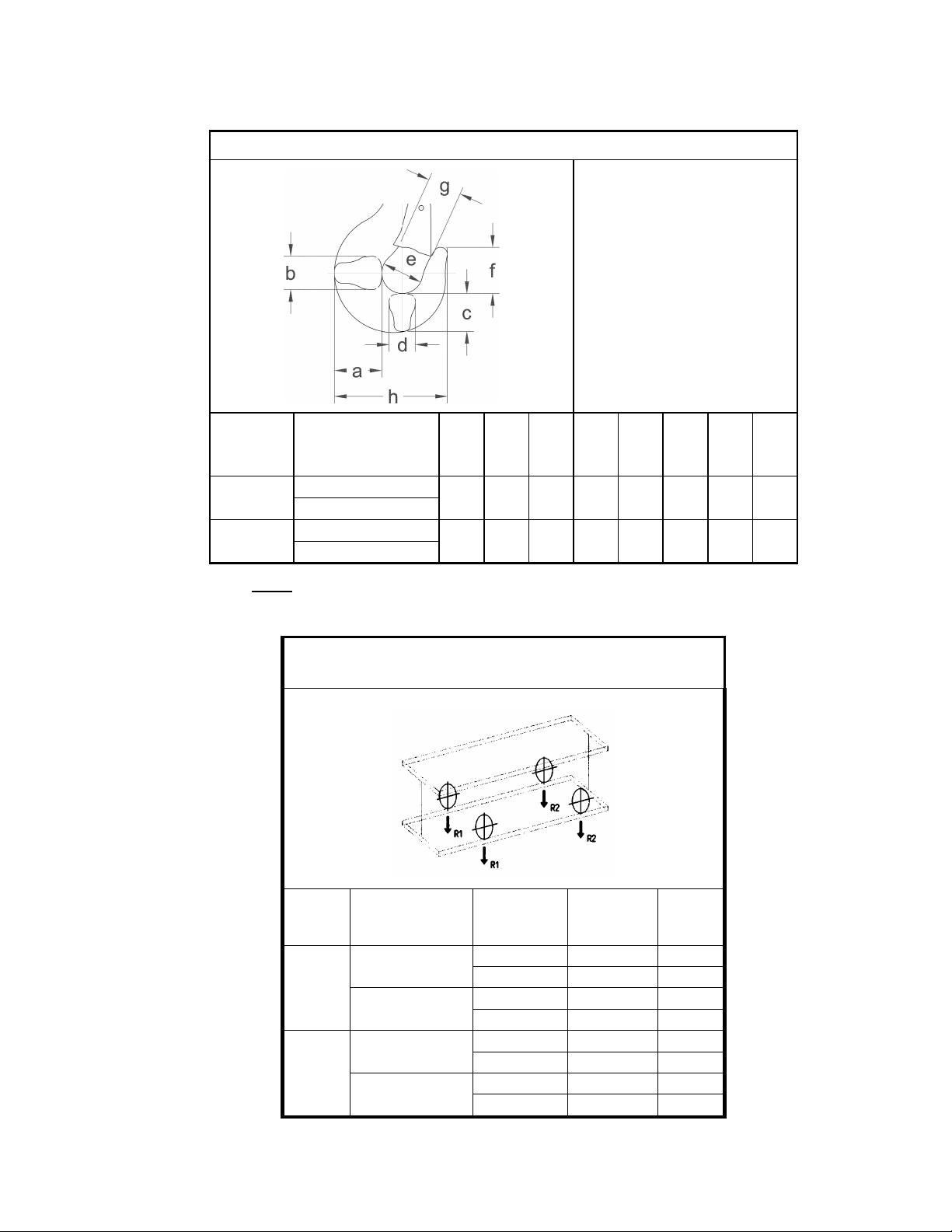
Table 2-7 Hook Dimension*
Units = inch
Capacity
(Tons)
3
5
Product Code
RYU030A25HDD
RYU030A33HDD
RYU050B25HDD
RYU050B33HDD
a
(in) b (in) c (in) d (in) e (in) f (in) g (in) h (in)
2.6 2.1 2.3 1.8 2.5 2.8 1.7 6.7
3.2 2.5 2.6 2.1 2.8 3.2 1.8 7.6
Notes: *Refer to Section 5, Table 5-6 for inspection dimensions and limits.
Table 2-8 Reaction Forces at Rated Load
Ultra-Low Headroom Monorail Trolley
Capacity
(Tons)
3
5
Product Code
RYU030A25HDD
RYU030A33HDD
RYU050B25HDD
RYU050B33HDD
Flange Range
B
(in)
4.92-13.78 2994 789
13.79-19.68 2999 790
4.92-13.78 3182 645
13.79-19.68 3187 646
4.92-13.78 4751 1252
13.79-19.68 4755 1253
4.92-13.78
13.79-19.68
R1
(lbs)
5032 1020
5037 1021
R2
(lbs)
13
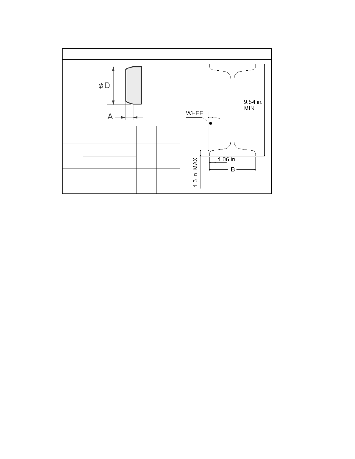
Table 2-9 Trolley Wheel Dimensions
Capacity
(Tons)
3
5
Product Code
RYU030A25HDD
RYU030A33HDD
RYU050B25HDD
RYU050B33HDD
A
(in)
0.79 3.86
0.79 3.86
φD
(in)
14
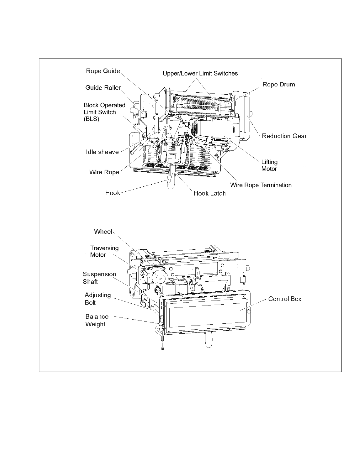
2.3 Part Names
Figure 2-1 RY Part Names
15
3.0 Pre-operational Pr ocedur es
3.1 General Information
3.1.1 When the RY trolley hoist is incorporated into lifting systems utilizing other equipment, follow and
complete all pre-operational procedures and instructions provided with the equipment. Special
wiring considerations must also be taken to complete the integration of the RY trolley hoist into
the system.
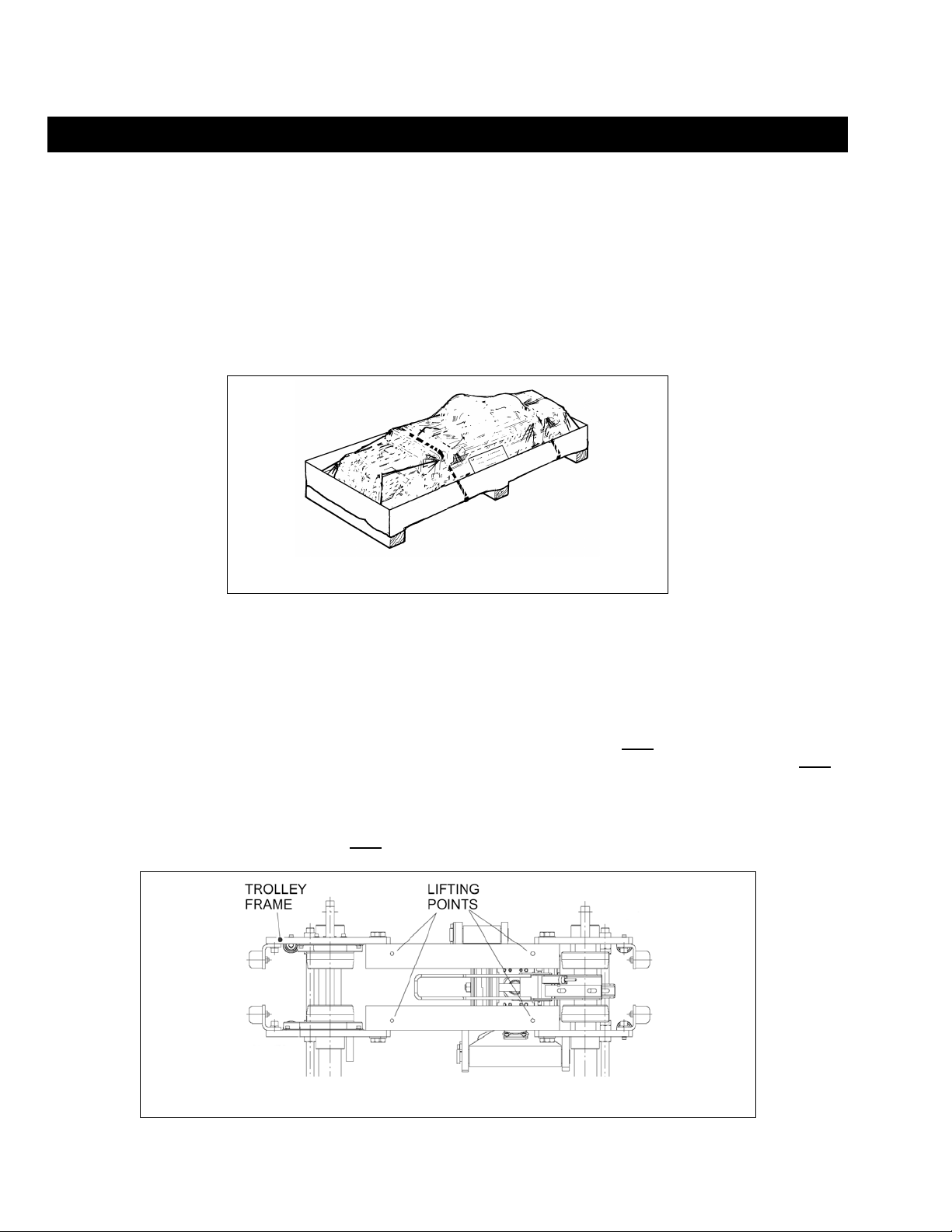
3.1.2 The RY hoist is delivered pre-assembled on a plastic-covered pallet/skid as shown in Figure 3-1.
During shipment and storage prior to installation, the trolley hoist should be kept between –4° and
+104°F (-20° and +40°C) and the relative humidity must not exceed 90%. The standard packaging is
not watertight and rainproof.
3.1.3 The RY trolley hoist is shipped with the wire rope installed and reeved from the wire rope drum through
the return sheaves and hook block to the dead end, reference Section 6.6.
3.1.4 The RY trolley hoist is shipped pre-lubricated with the correct amount of lubricant in the gear box(s).
Follow the lubrication requirements in Section 6.2 after the trolley hoist is placed into service.
3.2 Handling
3.2.1 Transportation – When moving the trolley hoist prior to installation, do NOT remove the trolley hoist
from the pallet. Always move trolley hoist utilizing a fork lift, pallet jack or hoist/crane system. Do NOT
stack or place anything on top of the trolley hoist or crate. Avoid swinging and unbalanced conditions.
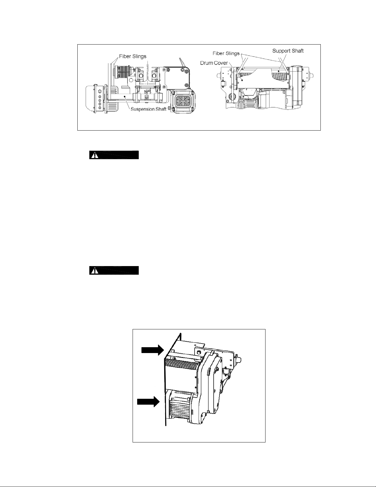
3.2.2 Lift points – When a pallet is not practical, use of the RY lifting points or the trolley frame is acceptable.
The RY trolley hoist is equipped with threaded lifting lugs in the horizontal tubes (see
Figure 3-3
Figure 3-1 Packaged as delivered
Figure 3-2 and
). While lifting do NOT support the trolley hoist any other way.
Figure 3-2 Lift Points for Trolley Hoist, 4 places. (M12mm Lifting Lugs Included)
16
3.3 Mounting Location
Figure 3-3 Sling Lifting Method
3.3.1
Prior to mounting the RY trolley hoist ensure that the wire rope has not loosened
on the wire rope drum. Due to vibration or other impacts during transportation of the product, the
wire rope wound on the Rope Drum may be loosened. Check for “slack” in the wire rope on the
drum. Remove all “slack” from the wire rope on the drum.
1) Pull the load side of the Wire Rope wound on the Rope Drum to remove slack and confirm
that the Wire Rope is settled in the groove of the Rope Drum.
2) If slack still remains, move the loosened part of the Wire Rope toward the Rope Guide side
so as to gradually remove the slack. When the slack reaches the Rope Guide, pull the Wire
Rope to completely remove the slack.
3) If slack cannot be removed by the steps above, detach the Rope Guide and remove the slack
and entanglement of the Wire Rope.
3.3.2 For the procedure of installation and removal of the Rope Guide, see Section 6.6.6 “Wire Rope
Installation/Rope Guide Installation”.
3.3.3
Prior to mounting the RY trolley hoist ensure that both the trolley beam lower
flange rating meets or exceeds the trolley hoist reaction forces listed in Table 2-8 and the beam
supporting structure is adequate to support the trolley hoist and its load. If necessary consult a
professional that is qualified to evaluate the adequacy of the suspension location and its supporting
structure.
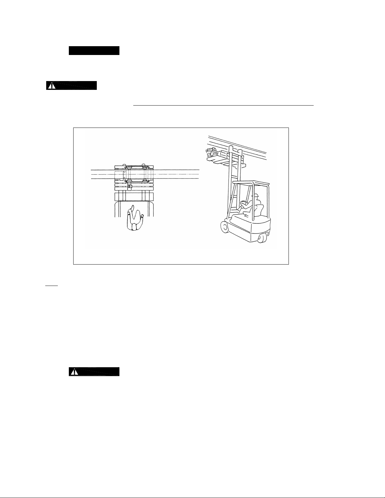
3.3.4 Ensure that there is adequate vertical and horizontal clearance along the entire range of the trolley
hoist’s motion as shown in Figure 3-4.
Figure 3-4 Trolley Hoist Clearances
17
3.3.5
See Section 6.8 for outdoor installation considerations.
3.4 Assembly, Adjustments and Mounting
When installing the trolley hoist on a beam, ALWAYS raise the hoist into position with the
trolley assembled together and securely attached to a pallet/skid. Raise the trolley hoist with a forklift, lifting
platform, or other similar means. NEVER use slings to raise and install the trolley hoist onto the beam.
forklift or another suitable means, position the pallet/skid so that the horizontal axis of the beam is parallel to the
horizontal axis of the trolley hoist as shown in Figure 3-6.
Using a
Figure 3-6 Trolley Secured to Pallet/skid for Installation
Note: Unless specified when ordered, the RY trolley hoist is factory set to accommodate a 4.92 to 13.78 inch
beam flange. A wider flange range for beams with flange widths 13.79 to 19.68 inches is available.
The RY is equipped with the maximum counterweight necessary for the standard and optional flange range,
4.92 to 19.68 inch, for each hoist capacity.
3.4.1 RY Trolley Hoist Installation
1) Make sure the mounting location complies with Section 3.3.
2) Install any additional devices, if any (power supply cords or pendants, for instance – see Section 3.7)
onto the trolley hoist. If the trolley hoist is not secured to a pallet, place and secure it to one making
sure that the trolley hoist is completely stable as shown in Figure 3-6.
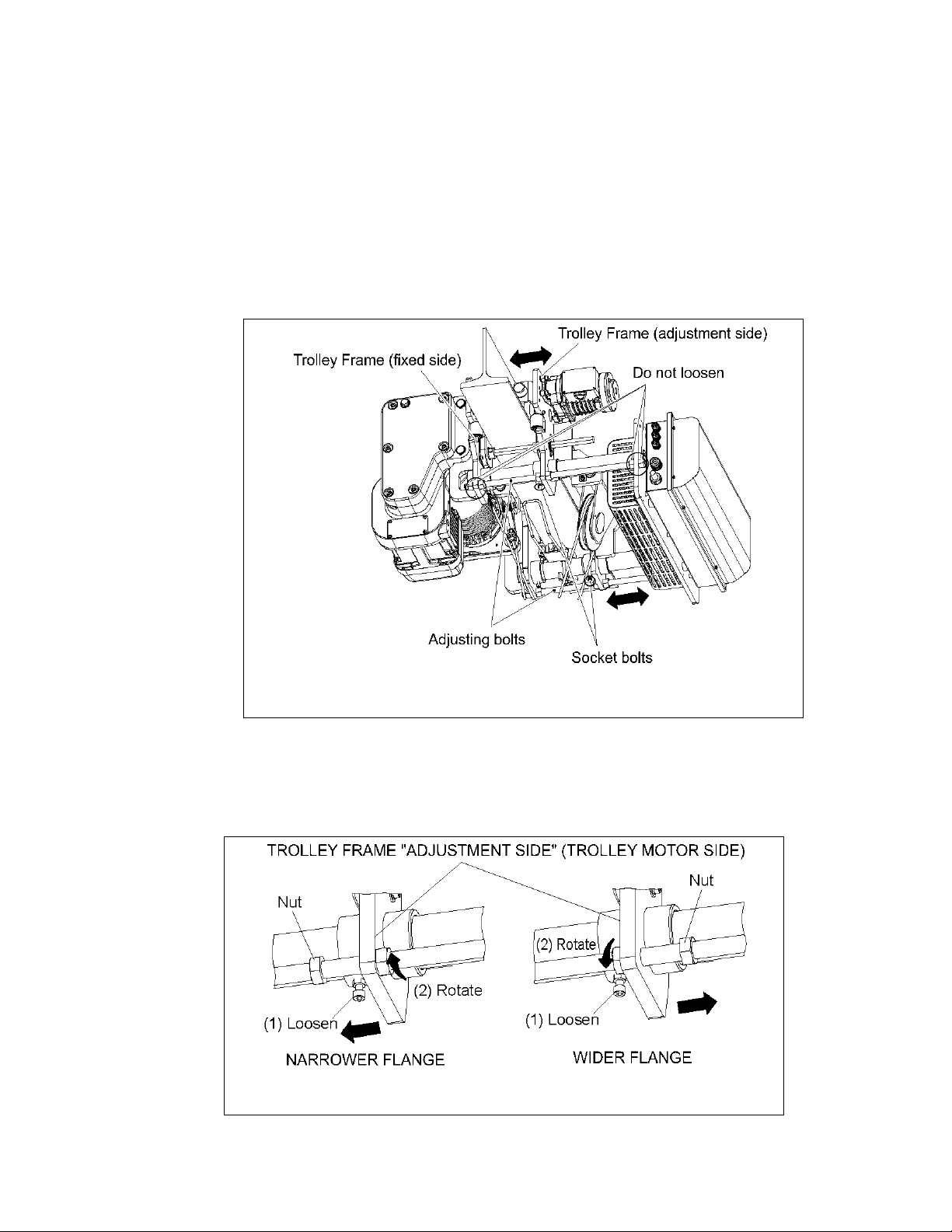
3)
the trolley. The “adjustment side” is easily identifiable as the trolley motor is bolted to it. Never loosen
the Adjusting Bolt Nuts on the “fixed side” or attempt to move the “fixed side” of theTrolley Frame. See
Figure 3-7 for Trolley Frame identification. Loosen the Socket Bolt attached to the lower side of the
boss on the Trolley Frame “adjustment side” (trolley motor) side as shown in Figure 3-7 and Figure 3-
8.
4) Before attempting to install the trolley hoist, verify beam width, “B” and the “A” dimension as shown in
Figure 3-10. Adjust flange width if necessary.
Only move/adjust the Trolley Frame “adjustment side” (side with trolley motor) of
18
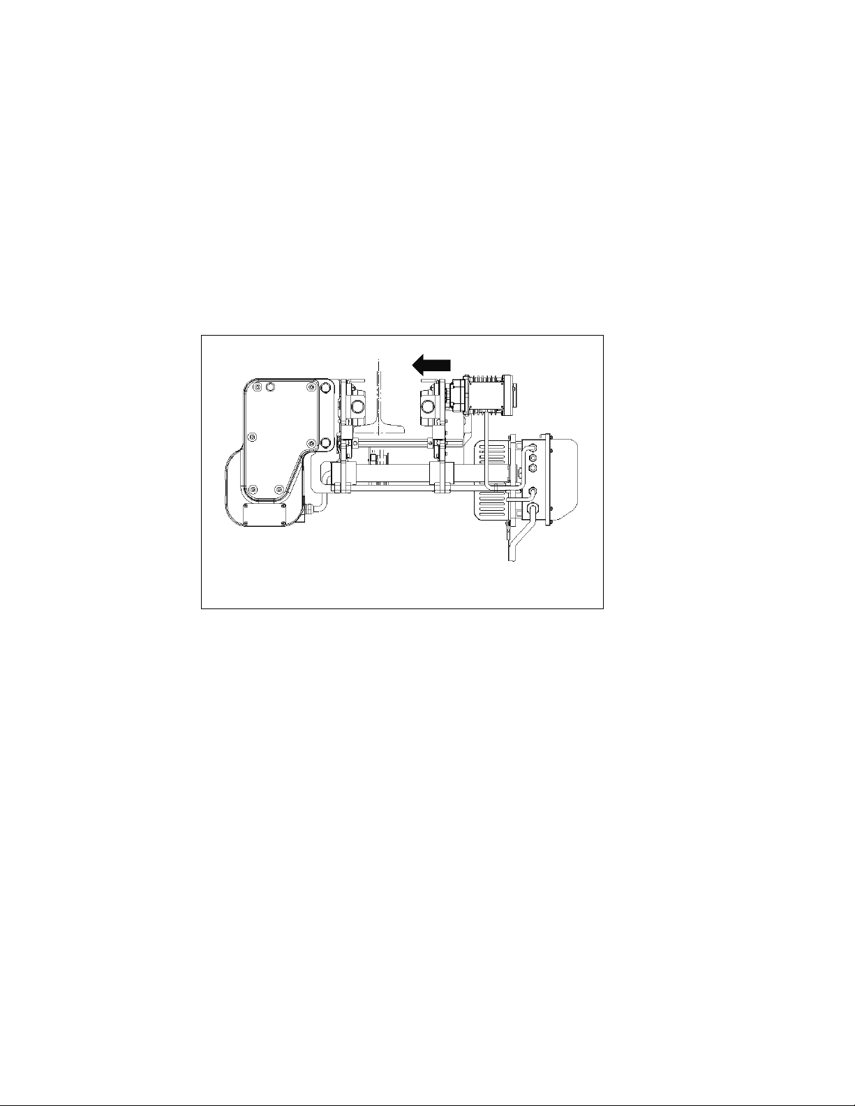
5) To adjust the flange width of the trolley, loosen the Socket Bolt located on the underside of the
“adjustment side” of the Trolley Frame on each as shown in Figure 3-7 and Figure 3-8.
To widen the flange width: Loosen the adjusting nut on the outer side of the trolley frame (adjustment
side) and tighten the nut on the inner side of the trolley frame (adjustment side) shown in Figures 3-8.
This must be performed uniformly on both Adjusting Bolt locations on each end of the hoist as shown in
Figures 3-7. Confirm dimension “A” as referenced in Figure 3-10.
To narrow the flange width: Loosen the adjusting nut on the inner side of the trolley frame (adjustment
side) and tighten the nut on the outer side of the trolley frame (adjustment side) shown in Figures 3-8.
This must be performed uniformly on both Adjusting Bolt locations on each end of the hoist as shown in
Figures 3-7. Confirm dimension “A” as referenced in Figure 3-10.
Figure 3-7 Adjusting distance between frames to accommodate beam
6) If the end of the runway beam is accessible, slide the trolley hoist onto the end of the runway
beam. Check the Trolley Wheel to Guide Roller clearance, “t”. “t” = 5/64 inch as shown in Figure
3-10. Adjust the Trolley Frame as necessary to meet the Trolley Wheel to Guide Roller
clearance, “t”. (See Section 3.4.1 Step 5 for proper adjustment procedure).
Figure 3-8 Loosen the Adjusting Bolt Nuts and Socket Bolts
19
7) If the end of the runway beam is not accessible, the trolley flange width will need to be opened up
to allow the Trolley Hoist to fit around the beam. (See Section 3.4.1 Step 5 for proper
procedure to widen flange width.)
8) Once the hoist is in position with the beam flange wheel running surface, the trolley flange can be made
narrowed to accommodate the respective beam flange width. Confirm dimension “t” = 5/64 inch as
shown in Figure 3-10. (See Section 3.4.1 Step 5 for proper procedure to widen flange width.
Figures 3-8, 3-9 and 3-10)
9) After adjusting the Trolley Frames for the correct beam flange width, tighten the Socket Bolt that was
loosened in step 3) and tighten the Adjusting Bolt Nut.
a. Socket Bolt Tightening Torque: 80 lbf-inch.
b. Adjusting Bolt Nut Tightening Torque: 111 lbf-ft
Figure 3-9 Trolley Sliding onto Beam
20
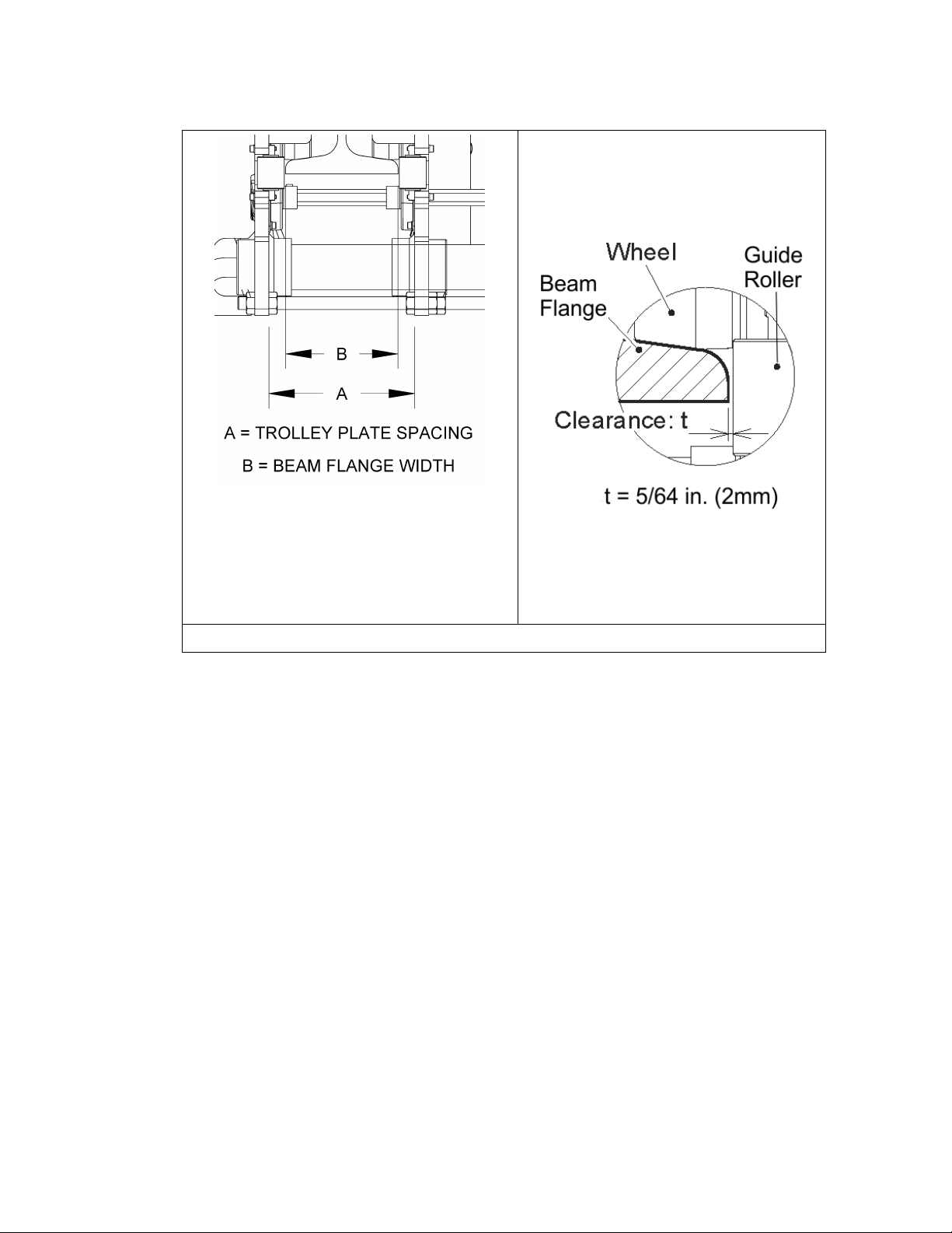
Note: A (trolley plate spacing) = B (beam
flange width) + 2 inches (inc. 5/64 in/2mm
space between each trolley wheel and guide
roller)
Figure 3-10 Trolley Flange Adjustment Example
21
3.5 Block Operated Limi t Switch (BLS) Adjustment
The BLS must be adjusted to where the Hoist and the Hook Block do not interfere with each other. The BLS
operates when the Upper/Lower Limit Switch does not function due to failure, improper setting, or abnormal
operation. The load can be lowered after the BLS has been activated.
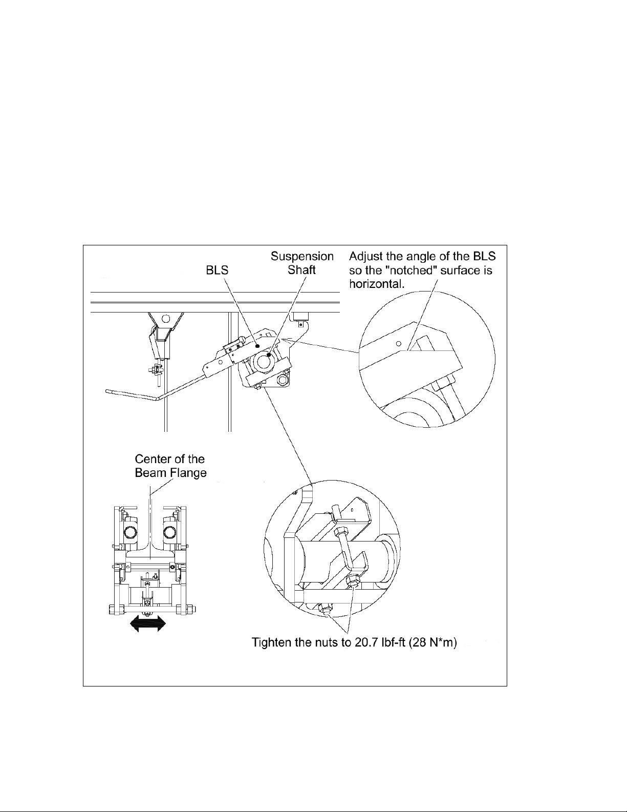
1) Because the BLS is attached to the Suspension Shaft, its position must be adjusted after installing the hoist
on the beam.
2) Adjust the position of the BLS to the center of the beam flange or the position where the center of the Hook
Block and the BLS can make contact, then set the angle of the lever to the position where the “notch” in the
BLS frame is horizontal (parallel to the beam flange) as shown in Figure 3-11.
3) Tighten the nuts to a torque setting of 20.7 lbf-ft (28 N• m).
Figure 3-11 Aligning BLS with beam center
22

3.6 Electrical Conn ect ions
3.6.1
3.6.2
3.6.3
3.6.4
3.6.5
3.6.6
3.6.7
If the Trolley hoist was supplied without a Power Supply Cable. The install er
must use a UL List power supply cable Type SJ, SJT, SO, SOO, SOOW, ST, STO or of a type at
least equally servicable for the particular application. Rated 90C, 600V minimum. Refer to total
AMP draw and NEC® (ANSI/NFPA 70, “National Electric Code”) guidelines when sizing appropriate
Power Supply Cable gauge. Alwa ys consult w ith a qualifie d pers on when appr o p r iate Pow er
Supply Cable sizing is in question.
Ensure that the voltage of the electric power supply is proper for the trolley hoist.
Do NOT apply electronic soft-start control or voltage varying controls to the RY.
Use of such devices may cause the motor brake and other electrical components to malfunction. The
RY lifting and traversing motions are variable frequency drive (VFD) controlled.
Before proceeding, ensure that the electrical supply for the hoist or trolley has
been de-energized (disconnected). Lock out and tag out in accordance with ANSI Z244.1 “Personnel
Protection -Lockout/Tagout of Energy Sources”.
To avoid a shock hazard, DO NOT perform ANY mechanical or electrical
maintenance on the trolley or hoist within 5 minutes of de-energizing (disconnecting) the trolley or
hoist. This time allows the internal VFD capacitor to safely discharge.
Do NOT remove power to the trolley hoist during operation.
All RY trolley hoists are dual speed hoists and trolleys that are equipped with
VFD’s. The VFD’s are used to control the high and lo w lift i ng and traversing speeds. The speeds
come preset from the factory (See Table 3-5). Speed (frequency) can be customized. Refer to
Section 3.8.13 for hoist specific speed ranges and instructions and Section 3.11.5 for trolley
traversing speed ranges and instructions.
3.6.8 Installing Power Supply Cord
1) Refer to Figure 3-12 and the wiring diagram provided with the Hoist.
2) Remove Control Cover.
3) Multiple cable fittings/clamps are available for use on both sides of the Control Panel for the Power
Supply Cord. Loosen the selected cable fitting/clamp and insert the Power Supply Cable. Pull
through enough cable to reach the power supply terminal and securely tighten the cable fitting as
shown in Figure 3-12.
4) Pull the Power Cable to check that it does not move in the cable fitting/clamp.
5) Connect the 3 phase power leads (L1, L2 and L3) and the ground lead of the Power Supply Cable
to the power supply terminals, Red, White, Black and Green/Yellow (ground). Make sure the
terminals are securely tightened and each lead is completely isolated as shown in Figure 3-12.
6) Connection to Electrical Power Source - The Red, White and Black wires of the Power
Supply Cable should be connected to an Electric Power Disconnect Switch or Circuit
Breaker.
7) Fuse/Breaker Capacity -The hoist's power supply should be equipped with current overload
protection such as fuses, which should be selected for 110% to 120% of total listed full load
amperage, and should be dual element time-delay fuses. Refer to the motor nameplate for
the full load amperage draw.
8)
electrical shock hazard when touching any part of the hoist or trolley. In the Power Supply
Grounding - An improper or insufficient ground connection creates an
23

Cable the ground wire will be either Green with Yellow stripe or solid Green. It should always
be connected to a suitable ground connection. Do not paint the trolley wheel running
surfaces of the beam as this can affect grounding.
9) Replace the Control Cover. Be careful to not damage the seal or sealing surfaces and make sure
to securely tighten all fasteners or latches.
3.7 Pendant Installation
If Trolley hoist was supplied without a Pendant/Control Cable. The installer must use
a UL List Pendant along with a UL Listed Pendant Cord/Control Cable Type SO, SOO, SOOW, ST, STO,
STOO or of a type at least equally servicable for the particular application and suitable for use with a
Pendant rated 60ºC minumum, 600V, 18 ga. minimum. Always consult with a qualified person when
appropriate Pendant Cable sizing is in question.
In outdoor, damp or applications subject to moisture, a NEMA 4 rated pendant shall
be used.
1) Refer to Figure 3-13, Figure 3-14 and the hoist wiring diagram for pendant connections.
2) Remove Control Cover.
3) Loosen the cable fitting located on the lower side of the electrical enclosure and insert the Pendant
Cable. Pull through enough cable to reach the terminals then securely tighten the cable fitting.
4) Attach a strain relief cable or chain between the pendant and hoist. The cable should attach to the
small plate located at the bottom of the electrical enclosure under the gear box.
5) Access to terminal strip: The terminal block/strip is mounted to the left of the VFD in the control box, as
shown in Figure 3-13.
Figure 3-12 Power Supply Connection Points
6) Connect the individual pendant leads to the correct terminals as shown in Figure 3-14. Make sure the
terminals are securely tightened and each lead is completely isolated.
7) Reinstall the Control Cover. Be careful to not to pinch any wires while closing and tightening down the
Control Cover.
8) Attach the pendant strain relief to the attachment point shown in Figure 3-15.
24
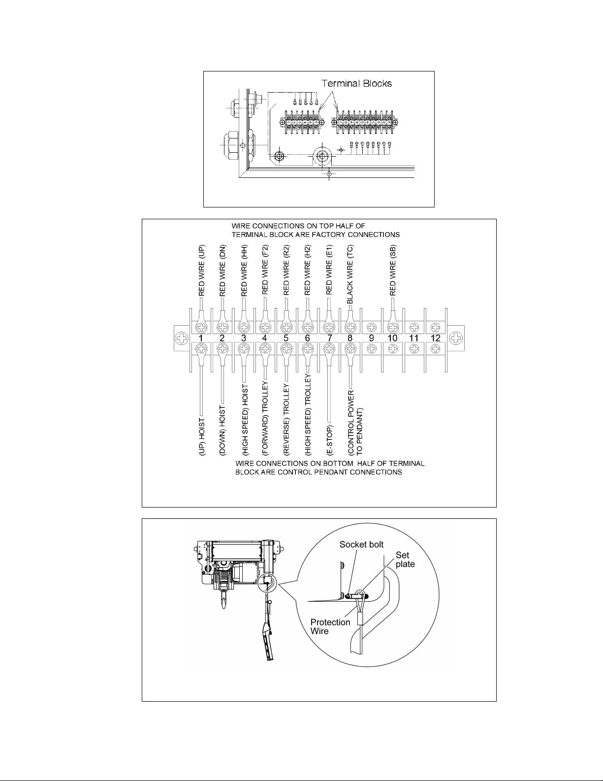
Figure 3-13 Pendant Terminal Block Location
Figure 3-14 Pendant Terminal Connection
Figure 3-15 Pendant Strain Relief Attachment
25

3.8 Hoist Variable Frequency Drive (VFD) Setup
The hoist Lifting/Lowering VFD is located in the Trolley Hoist Control Box as shown in Figure 3-16.
Figure 3-16 VFD Locations
3.8.1
maintenance on the dual speed (VFD control) trolley or hoist within 5 minutes of de-energizing
(disconnecting) the trolley or hoist. This time allows the internal VFD capacitor to safely
discharge.
3.8.2
3.8.3
procedures before working on the VFD.
3.8.4 All hoists are equipped with a VFD. The VFD is used to control the high and low lifting speeds.
The speeds come preset from the factory (Table 3-5). Speed (frequency) can be customized.
Refer to Section 3.8.13 for hoist specific speed ranges and instructions.
3.8.5
person with experience and expertise of handling the wire rope hoist and the VFD control.
3.8.6
VFD. Do NOT
components around the VFD.
3.8.7 The VFD is controled by a Keypad/Display Interface. Refer to Figure 3-17 for Keypad/Display
Interface functions and desc r iptions .
To avoid a shock hazard, DO NOT perform ANY mechanical or electrical
Do NOT remove power to the VFD control hoist or trolley during operation.
Ensure proper Electro-Static Discharge (ESD) component safe handling
Parameter change and maintenance must be performed by a competent
The product is energized during a parameter change or maintenance of the
remove the cover of the VFD. Do NOT touch the circuit board or electrical
26
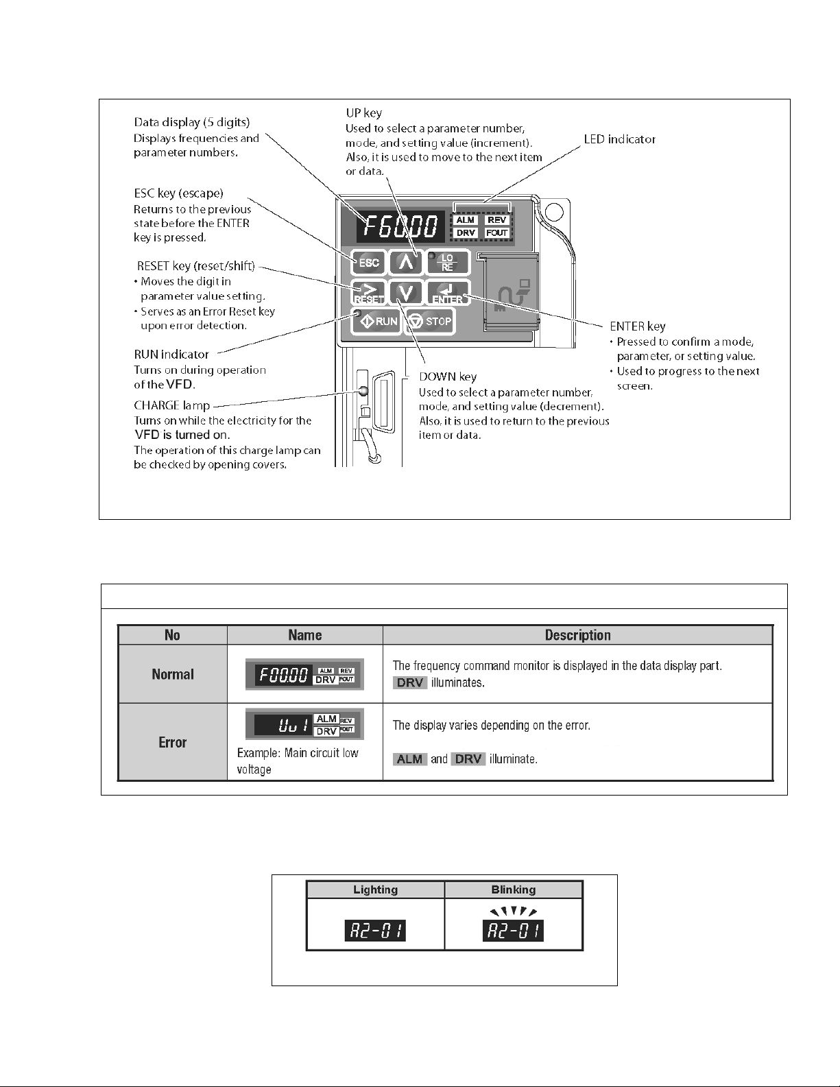
Figure 3-17 VFD Keypad/Display Interface
3.8.8 When power is supplied to the hoist the VFD LED operator dis pl a y will illum inate a s shown Table
3-1.
Table 3-1 LED Operator Display
3.8.9 During operation the data display will exhibit illuminating or blinking data as shown in Figure 3-
18.
Figure 3-18 Illuminating/Blinking Display
27
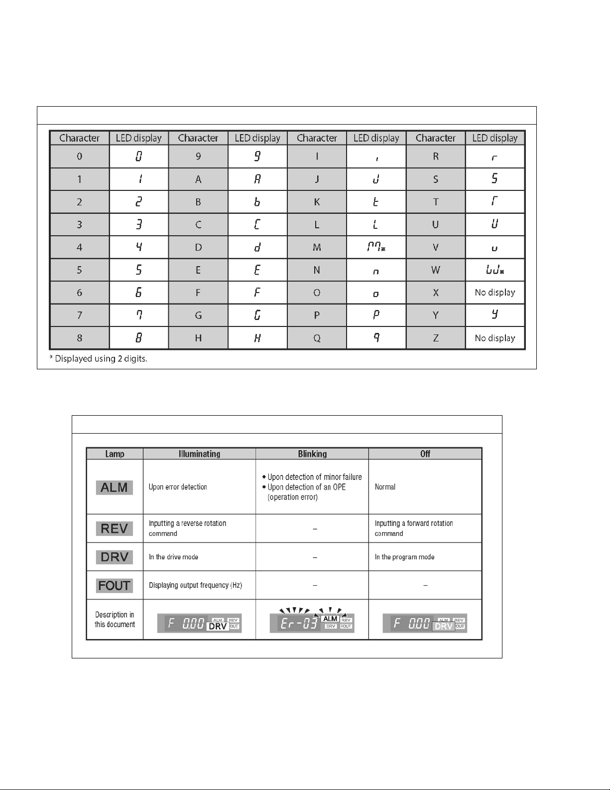
3.8.10 The digital display uses a seven segment character to form the specific charaters used in the
display. Table 3-2 shows the corresponding digital characters to its English eqivalent.
Table 3-2 Digital Character Key
3.8.11 The LED Lamp display provides hoist status. Table 3-3 shows some of the status displays.
Table 3-3 LED Lamp Display
3.8.12 The Run Lamp display provides hoist “RUN” status. Table 3-4 shows the various “RUN”
displays.
28
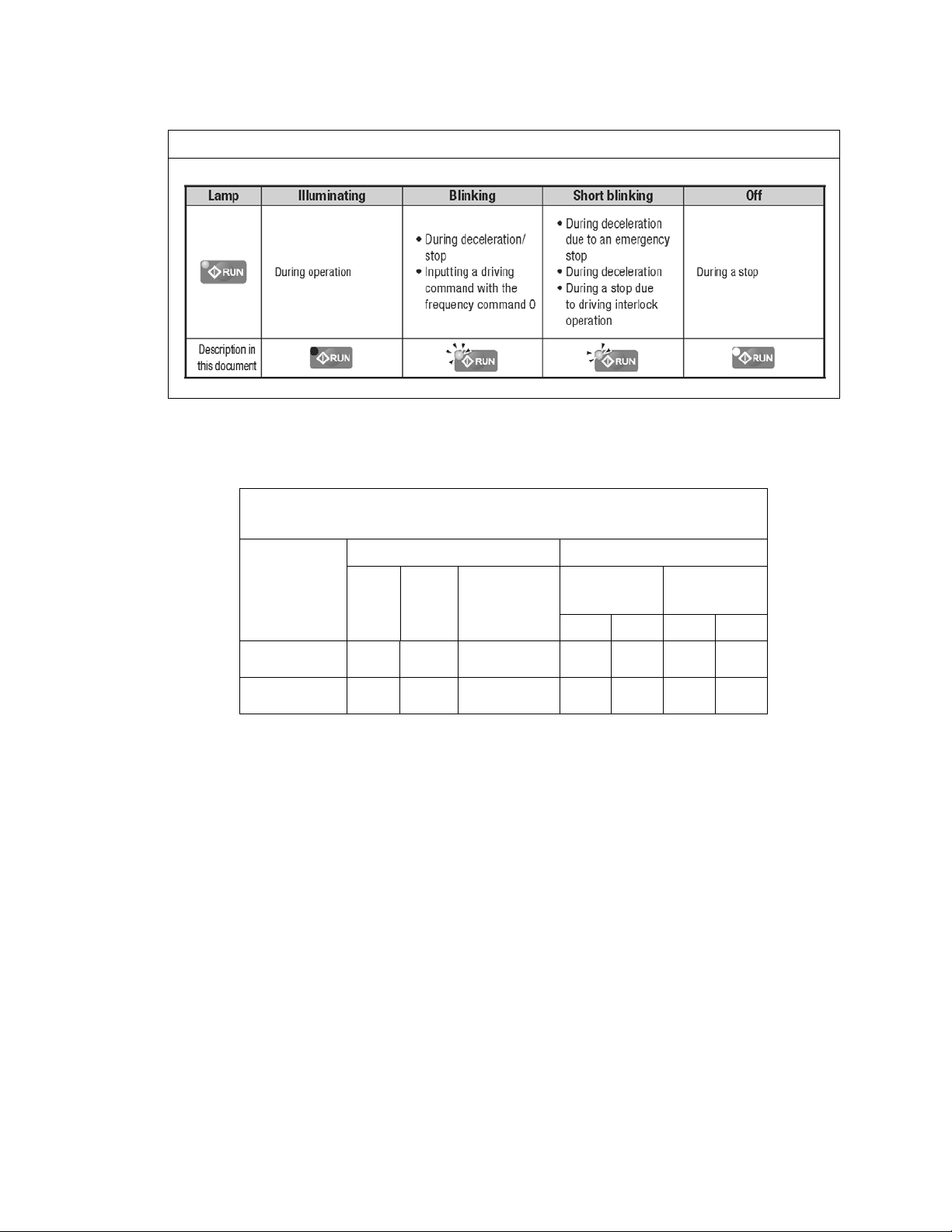
Table 3-4 Run Lamp
3.8.13 All of the hoists have speed/frequency ranges that can be customized to a specific application.
Refer to Table 3-5 for specific hoist speed/frequency ranges. To set custom speeds for an
application, follow the procedure listed in Table 3-6 and refer to the speed/frequency Table 3-7.
Table 3-5 Hoist Speed and VFD Frequency Ranges
200V = 208 – 230V / 400V = 415 – 460V
1
Lifting Speed
(ft/min) VFD Frequency1 (Hz)
Product
Code
Low High
No Load
High
2
Speed
Low (d1-01) High (d1-02)
200V 400V 200V 400V
RY030 4.3 26 39 8.5 8.6 57.7 56.5
RY050 4.3 26 39 8.3 8.4 56.5 57.5
The factory standard minimum and maximum speed/frequency range (6:1 ratio).
1)
2) The “Light-Load High Speed” feature is not an adjustable parameter. It can be
turned on/off using the instructions in Table 3-8.
29

(Example Value: 8 Hz)
Table 3-6 Hoist VFD Speed/Frequency Change Procedure
Each dual speed hoist model has a range of available speeds/frequencies (upper and lower limits).
Any value outside the range listed in Table 3-5 for your specific hoist is strictly prohibited.
Speeds must be set such as Low [d1-01] and High [d1-02].
After parameters are changed, a “no load” operational check must be performed.
Operational Step VFD Display
1. Energize the hoist.
2. Press until the “Setup Mode” screen is displayed (blinking).
3. Press to display the parameter setting screen (blinking).
4. Press or until the desired parameter is displayed (blinking).
(Low Speed: d1-01, High Speed: d1-02)
5. When you press , the current setting value is displayed (digit selected blinks).
(Example Value: 9 Hz)
6. Press to move the blinking digit to the desired digit.
(Example Value: 9 blinks)
7. Press or until the desired setting is displayed and press .
8. Press to confirm the new setting.
9. The display will automatically return to the parameter screen (blinking).
(As in Step 4.)
10. Press until the diplay returns to the initial scr een.
(As in Step 1.)
30
 Loading...