

KITO ER2, ER2SP, ER2M, ER2SG Owner's Manual

OM-ER2ZZZ-MGE-00
ER2 Series Electric Chain Hoist
Owner's Manual
Hook Suspended Type (hoist only) : ER2
Motorized Trolley Type : ER2M
Manual Trolley Type : ER2SP/ER2SG
(125kg to 5t)
To Customer
• Thank you for purchasing KITO Electric Hoist (ER2).
• Operators and maintenance engineers are requested to read this manual.
After reading, please keep this manual at hand for future use.
• This product is designed considering the environment protection. The product contains none of six hazardous
substances specified by European RoHS Directives nor asbestos.

Table of Contents
Introduction ............................................................................................2
Safety Precautions ................................................................................4
Chapter 1 Handling the Product ..........................................................7
Chapter 2 Inspection ..........................................................................63
Chapter 3 Troubleshooting ................................................................93
Appendix ............................................................................................119
Warranty .............................................................................................162
Introduction
This electric hoist ER2 is designed and manufactured for the purpose to lift and lower a load within a normal
work environment. The motorized trolley MR2 and the manual trolley are designed and manufactured for the
purpose to move the lifted load laterally with the combination with the electric hoist.
Movement of a load in a 3D direction such as up/down, forward/backward and right/left is also enabled by
combining with a crane.
This Owner's Manual is intended for those operating the KITO electric hoist ER2 and maintenance engineers
(* pesonnel with expertise).
Other than this manual, Disassembly/Reassembly Manual and Parts List are also available for the maintenance
engineers. Assign the maintenance engineers and use these materials for inspection and repair. Please contact
the nearest distributor or KITO for these materials.
■Disclaimer
●
KITO shall not be liable for any damage incurred thereof due to natural disaster such as fire, earth quake
and thunderbolt, conduct by third party, accident, willful conduct or negligence by customer, erroneous use
and other use exceeding the operational condition.
●
KITO shall not be liable for any incidental damage due to the use or non-use of the product such as the loss
of business profit, suspension of business and damage of the lifted load.
●
KITO shall not be liable for any damage arising from negligence of the contents in the Owner's Manual and
the use of the product exceeding the scope of its specification.
●
KITO shall not be liable for any damage arising from the malfunction due to the combination of the product
with other devices in which KITO is not concerned.
●
KITO shall be indemnified from any loss of life, bodily injury and property damage due to the use of our
product for which it has passed 10 years since its delivery.
●
KITO shall not be liable to supply the spare parts for the product for which it has passed for 15 years since
the discontinue of the product.
2

■Restriction on Use
●
The product described herein is not designed or manufactured for transporting people. Do not use the
product for that purpose.
●
The product described herein is designed for the materials handling work such as lifting/lowering and
traveling the load under ordinary operational condition. Do not use the product for the work other than
materials handling work.
●
Do not assemble the product into machinery not for materials handling, as a part of it.
■Operators
●
Read carefully this Owner’s Manual and the instruction manuals of related products, fully understand their
contents, and the use and operate the product.
●
Be sure to ware the proper clothing and protective equipment when using and operating the product.
■Laws and Standards
Carry out installation, inspections, operations, maintenance management in accordance with the laws and
standards of the country and region where the product is used.
An application before installation or a test before beginning usage may be required. Furthermore, the tester
may be required to have specific qualifications. Be sure to check the laws and standards of the corresponding
country and region before using the product.
3
Safety Precautions
Improper use of electric chain hoist causes danger such as drop of lifted load. Read this Owner’s
Manual carefully before installation, operation and maintenance. Use the product after understanding the
product knowledge, safety information and precautions.
This Owner’s Manual classifies the safety information and precautions into two categories of “DANGER”
“WARNING” and “CAUTION”.
Also read the instruction manual of the device associated with electric chain hoist, and follow the
described contents.
Description of Signal Words
DANGER
injury.
Indicates a potentially hazardous situation which, if not avoided, could result in death or serious
Indicates an imminently hazardous situation which, if not avoided, will result in death or serious
WARNING
injury.
Indicates a potentially hazardous situation which, if not avoided, may result in minor or moderate
CAUTION
Further, the event described in CAUTION may result in serious accident depending on the situation. Both DANGER and CAUTION
describe important contents. Please follow the instruction.
After reading, please keep this manual at hand for future use by the user.
injury. It may also be used to alert against unsafe practices.
Description of Safety Symbols
Means “Prohibited” or “You must not do”.
Prohibited action is shown in the circle or described near the circle.
Prohibited
Mandatory
This Owner’s Manual uses
Means “Mandatory Action” or “You must do”.
Required action is shown in the circle or described near the circle.
This Owner’s Manual uses
as the general prohibition.
as the general instruction.
■General Matters on Handling and Control
DANGER
• This product shall not be disassembled and repaird by personnel other than maintenance engineers.
Other than this manual, Disassembly/Assembly Manual and Parts List are provided for the maintenance engineers.
Prohibited
Mandatory
4
Per form the disassembling and repair by the maintenance engineer in accordance with these materials for
maintenance.
• Do not modify the product and its accessories.
Failure to comply with these instructions may result in death or serious injury.
• Understand the contents of the Owner’s Manual sufficiently. Then operate the Electric chain hoist.
• Warning label is affixed to each part of the product. Follow the instruction described in the warning label.
Failure to comply with these instructions may result in death or serious injury.
CAUTION
• Do not drag or drop the product when carrying.
Otherwise it causes damage or flaw of the electric chain hoist, bodily injury or loss of property due to the drop of the
Prohibited
Mandatory
lifted load.
• When discarding the product, disassemble it not to be used and discard in accordance with the
ordinances of local government or the rules specified by the business entity.
Ask the local government or the relevant section for the details.
Refer to “Disassembly/Assembly Manual” for disassembling, or contact KITO.
(This product uses oil. We prepare MSDS (Materials Safety Data Sheet) for the oil. Contact KITO for it.)
• Carry out daily inspection by user.
• Carry out inspection (monthly, annual) by maintenance engineer.
• Keep the record of the inspection.
Failure to comply with these instructions causes bodily injury or loss of property.
■General Matters on Handling of Dual Speed VFD Model
The dual speed VFD model electric chain hoist is controlled by VFD for important items related to safety such as
operation, braking and emergency stop. Be sure to follow the safety precautions below as well as the above safety
precautions.
Prohibited
DANGER
• Do not change parameters.
When parameters need to be changed, ask distributor or KITO.
• Do not carry out the work such as maintenance and inspection within 5 minutes after power off.
Wait for the completion of discharging of the capacitor inside the VFD.
• Do not touch the controller cover as it becomes hot during operation.
Do not touch the controller cover until about 30 minutes elapsed after the stop of operation.
• USE KITO genuine VFD.
The VFD requires the special specification for KITO. Be sure to use genuine VFD.
• Do not change the connection of the VFD.
When the wires were removed for any reason, connect them again correctly checking the wiring diagram inside the
controller cover.
• Do not carry out withstand voltage test and insulation resistance measurement of a circuit by megger
while the VFD is connected.
• Do not turn off the power while operating.
Failure to comply with these instructions may result in death or serious injury and the damage of VFD.
5

6

Chapter 1
Handling the Product
This chapter describes mainly how to use, assemble and install, and the check
after installation. It also describes the daily inspection items before use.
For Operators and Maintenance Engineers
●
Type and Names of Each Part ..........................................................8
Opening the Package ......................................................................11
Product Specication and Operational Environment ..................16
How to Use ......................................................................................19
● Daily Inspection of Electric Chain Hoist (Hook Suspended Type)
● Daily Inspection of Motorized Trolley (MR2) .............................25
● Daily Inspection of Manual Trolley (TSG/TSP) ..........................26
● How to Operate the Push Button Switches ...............................28
● Operation ......................................................................................31
● Speed Change of Dual Speed VFD Model .................................34
● How to Sling the Load Properly .................................................34
● How to Suppress the Swinging of a Load .................................34
● Precautions After Work ...............................................................35
20
For Maintenance Engineers and Installars
●
Work Flow of Assembling and Installation....................................36
Assembling ......................................................................................37
● Assembling Parts to Electric Chain Hoist .................................37
● Combination with the Trolley ......................................................41
● Checking Power and Power Cable .............................................52
● Connecting Cables ......................................................................54
Installation ........................................................................................57
● Connecting Power and Power cable ..........................................57
● Installing the Hook suspended Type (hoist only).........................57
● Installing the Trolley Combined Model .......................................58
Check after Installation ...................................................................61
7

Chapter 1 Handling the Product
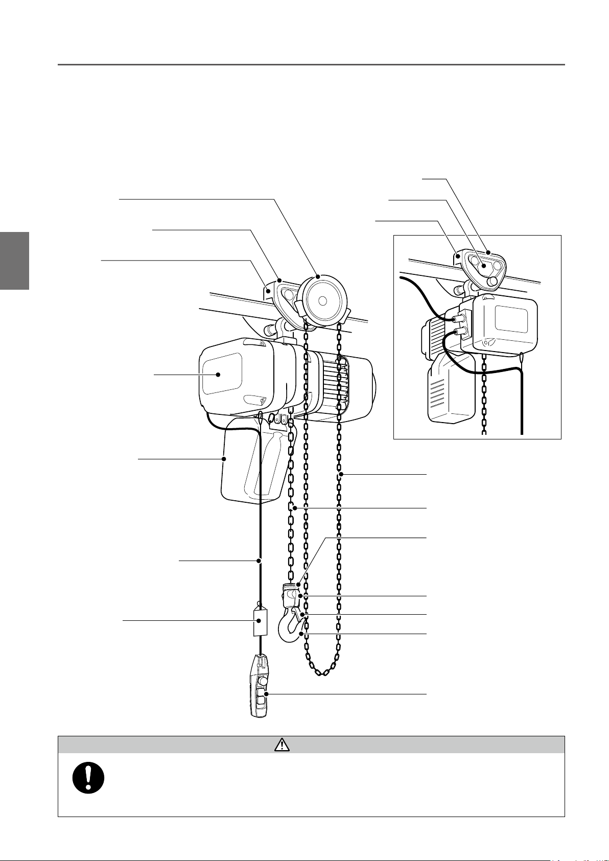
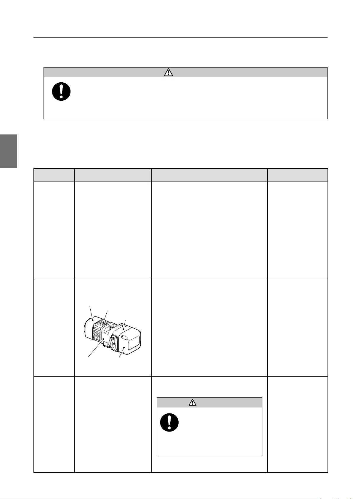
Type and Names of Each Part
■Hook Suspended Type (ER2)
●
Electric chain hoist dedicated for elevation
Type and Names of Each PartHook Suspended Type (ER2)
1
Electric Chain hoist
name plate
Chain Container
Push Button
Switch Cord
Top Hook
Body
Load Chain
Cushion Rubber
(Chain spring and end plate for the
model of rated load 2 t or more)
Bottom Yoke
Warning Tag
Mandatory
Hook Latch
Bottom Hook
Push Button Switch
DANGER
• Warning labels are affixed to each part other than above. Be sure to follow the instructions in the label.
Failure to comply with the contents of the label may result in death or serious injury.
8

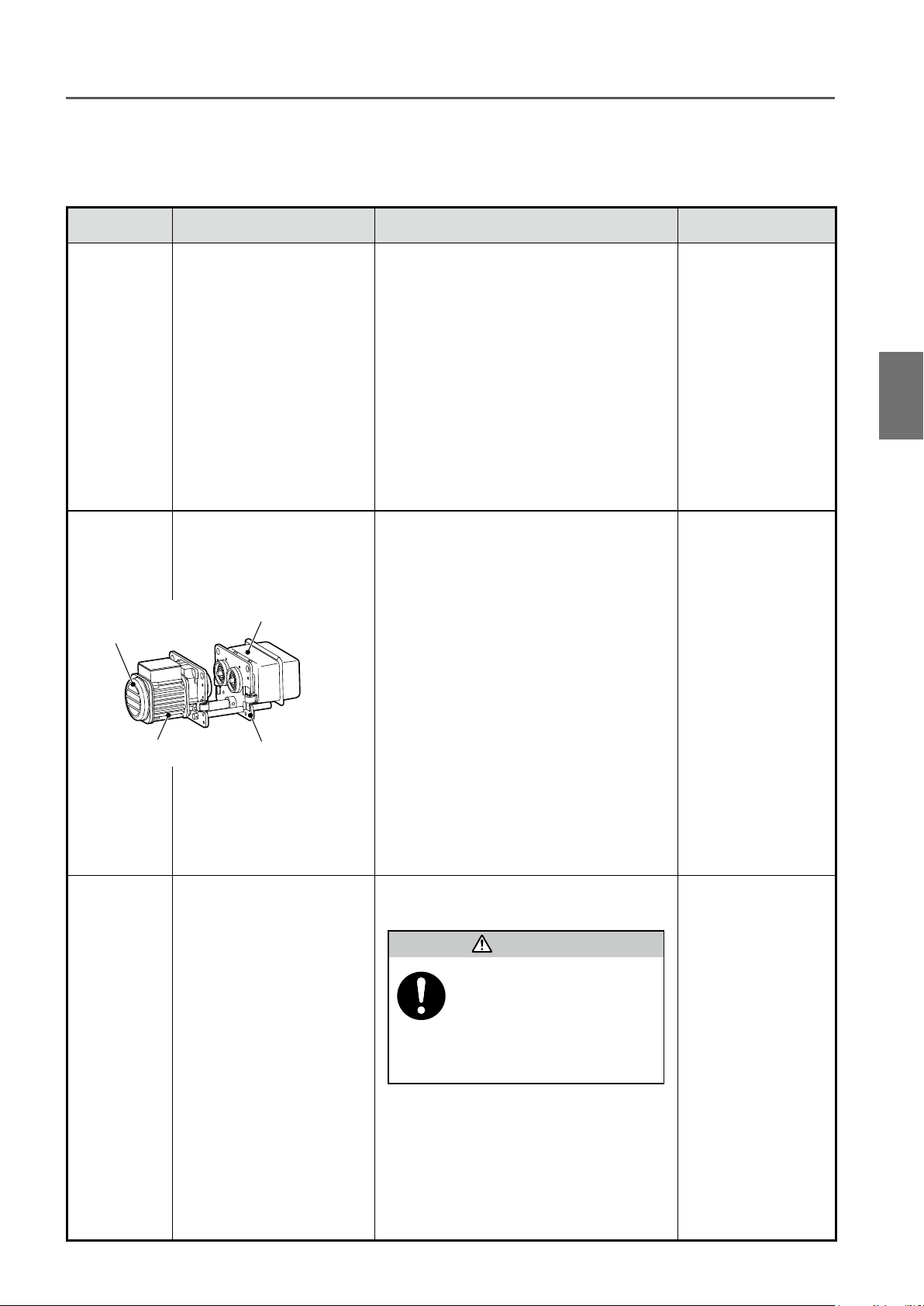
■Motorized Trolley Type (ER2M)
●
Electric Chain Hoist combined with motorized trolley (MR2) for elevation and traveling motion
Motorized trolley
nameplate
Connection Box
Cable Support Bar
Type and Names of Each Part Motorized Trolley Type (ER2M)
Relay Cable
Chain Container
Load Chain
1
Power Cable
Electric chain hoist
nameplate
Push Button
Switch Cord
Warning Tag
Cushion Rubber
(Chain spring and end plate for the
model of rated load of 2 t or more)
Bottom Hook
• Warning labels are affixed to each part other than above. Be sure to follow the instructions in the label.
Failure to comply with the contents of the label can result in serious bodily injury or death.
Mandatory
DANGER
Bottom Yoke
Hook latch
Push Button Switch
(to be continued)
9
Chapter 1 Handling the Product
Chain Container
Electric chain hoist
nameplate
Push Button Switch Cord
Warning Tag
Load Chain
Cushion Rubber
(Chain Spring and End Plate for the
model of rated load 2 t or more)
Hand Chain
Bottom Yoke
Hook Latch
Bottom Hook
Push Button Switch
Geard Trolley (TSG)
Bumper
Hand Wheel
Type and Names of Each Part (continued)
■Manual Trolley Type (ER2SG/ER2SP)
●
ER2SG : The electric chain hoist equipped with the geared trolley (TSG) enabling fine
adjustable lateral motion of the load by pulling the hand chain.
●
ER2SP : The electric chain hoist equipped with the plain trolley (TSP) enabling lateral motion by moving the
load manually. For light work.
Plain Trolley (TSP)
Nameplate
Type and Names of Each PartManual Trolley Type (ER2SG/ER2SP)
1
Bumper
Mandatory
DANGER
• Warning labels are affixed to each part other than above. Be sure to follow the instructions in the label.
Failure to comply with the contents of the label can result in serious bodily injury or death.
10

Opening the Package
■Checking the Product
●
Make sure that the indication on the package and the product coincide with your order.
●
Make sure that the product is not deformed and damaged due to the accident during transportation.
■Packaging
■Packaging
For the customer's convenience, the main parts of our product are packaged individually and delivered.
Electric chain hoist main
unit packaging
Equipped with
Top Hook
ER2
Equipped with
Connection Yoke
Accessory set
3-Push
Button
Switch set
Power
Cable set
Trolley packaging
TSP Plain Trolley
Applicable model
Hook Suspended
Model
Plain Trolley
Combined Model
Geared Trolley
Combined Model
Opening the Package Checking the Product / Packaging
1
ER2SP,
ER2SG
Equipped with
Suspender
ER2M
* Power Cable longer than 10 m is available as an optional part.
5-Push
Button
Switch set
Button
Switch set
TSG Geared Trolley
Model MR2
Motorized Trolley
■Parts packaged with the Electric Chain Hoist
Plastic or canvas
Chain Container (option)
Owner's Manual
Option
Power *
Cable
Power *
Cable
Load Chain
Grease Tube
Motorized Trolley
Type
Crane
Control Box7-Push
(to be continued)
11
Chapter 1 Handling the Product
Opening the Package (continued)
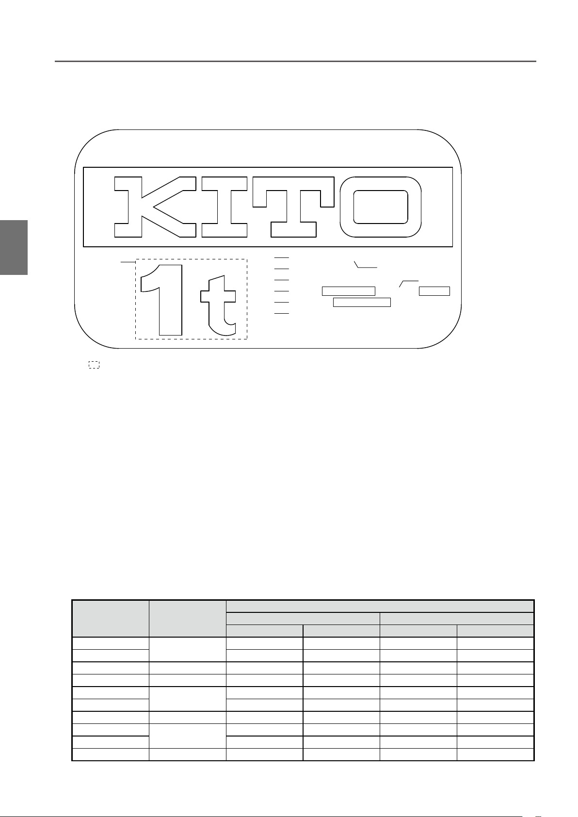
■Nameplate and Product Model
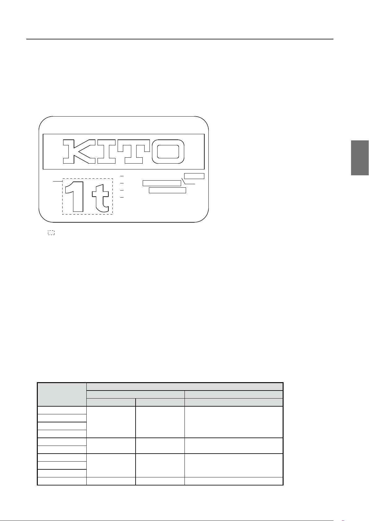
■Nameplate Indication of Electric Chain Hoist
Opening the PackageNameplate and Product Model
1
1
· · · Capacity Ex. 1t, 500kg
1
Th e maximu m mass of the lo ad that can be
imposed on the product. The mass of the hook is
excluded.
SIZE…Body size Ex. Body size C, ER2-C
2
Th e si z e of the electric chain hois t bo d y to
support the load. Five models of B, C, D, E and F
are provided.
GRADE Ex. M4, M5
3
The grade of an electric chain hoist specified by
ISO standard. A guidepost of durability.
CODE…Product model Ex. ER2-005S
4
A code to indicate the model No. of the product,
capacity and lifting speed.
CHAIN SIZE…Load Chain size
5
Ex. T-7.7×21.4mm
The alphabet and the figures indicate the JIS
2
4
5
6
8
9
SIZE: ER2-D GRADE: M5
CODE: ER2-010S
CHAIN SIZE: T-7.7×21.4mm
LOT No: MFG.YEAR
SERIAL No:
LIFTING SPEED: 0.118 m/min 50Hz
grade, wire diameter and chain pitch respectively.
LOT No.
6
Manufacture No. to identify the time of manufacture
and the production lot.
MFG. YEAR…Manufacture year
7
SERIAL No.
8
Serial number to indicate the manufacturing sequence
of the product.
LIFTING SPEED
9
Single speed model and dual speed VFD model
are provided. Variable speed range and its set
value are indicated for the dual speed VFD model.
3
: 0.142 m/min 60Hz
7
12
■Code of ER2
Capacity Body Size
125kg
250kg ER2-003S (ER2-003H)* ER2-003IS/SD (ER2-003IH/HD)*
500kg ER2-C ER2-005S ER2-005L ER2-005IS/SD ER2-005IL/LD
1t ER2-D ER2-010S ER2-010L ER2-010IS/SD ER2-010IL/LD
1.5t
2t ER2-020S ER2-020L ER2-020IS/SD ER2-020IL/LD
2.5t ER2-F ER2-025S — ER2-025IS/SD —
2.8t
3t ER2-030S — ER2-030IS/SD —
5t ER2-F ER2-050S — ER2-050IS/SD —
* Hight Speed Type
ER2-B
ER2-E
ER2-E
CODE
Single speed model Dual speed model
Standard speed Low speed Standard speed Low speed
— (ER2-001H)* — (ER2-001IH/HD)*
ER2-015S — ER2-015IS/SD
ER2-028S — ER2-028IS
■Nameplate Indication of Motorized Trolley
CODE: MR2-010S MFG.YEAR
1
· · · Capacity Ex. 1t, 500kg
1
The maximum mass of the load that can be imposed on the
product. The mass of the hook is excluded.
CODE · · · Product model Ex. MR2-010S
2
A code to indicate the model No. of the product, capacity and
traveling speed.
MFG. YEAR…Manufacture year
3
LOT No.
4
Manufacture No. to identify the time of manufacture and the
quantity of a production unit.
SERIAL No.
5
Serial number to indicate the manufacturing sequence of the
product.
TRAVELING SPEED
6
Single speed model and dual speed VFD model are provided.
Variable speed range and its set value are indicated for the
dual speed VFD model.
2
LOT No:
4
SERIAL No:
5
TRAVELING SPEED:
6
0.333 m/min 50Hz
0.400 m/min 60Hz
3
Opening the Package Nameplate and Product Model
1
■Code of MR2
Capacity
125kg
250kg
500kg
1t
1.5t
2t
2.5t
3t
5t MR2-050S MR2-050L MR2-050IS/SD
CODE
Single speed model Dual speed model
Standard speed Low speed Standard speed
MR2-010S MR2-010L MR2-010IS/SD
MR2-020S MR2-020L MR2-020IS/SD
MR2-030S MR2-030L MR2-030IS/SD2.8t
(to be continued)
13
Chapter 1 Handling the Product
Opening the Package (continued)
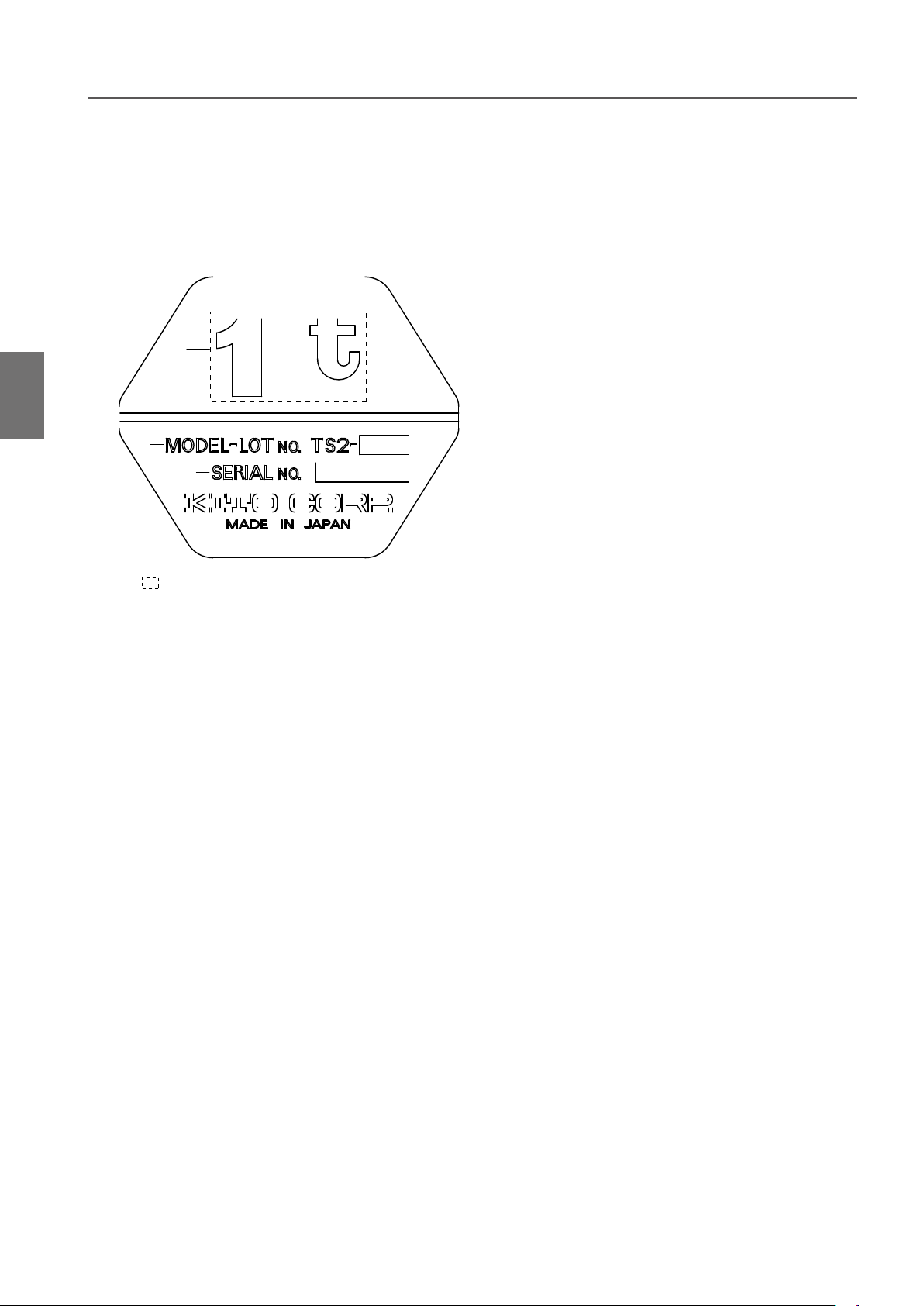
■Nameplate Indication of Manual Trolley
Opening the PackageNameplate and Product Model
1
1
2
3
· · · Capacity Ex. 1t, 500kg
1
The maximum mass of the load that can be imposed on the
product. The mass of the hook is excluded.
LOT No.
2
Manufacture No. to identify the time of manufacture and the
production lot.
SERIAL No.
3
Serial number to indicate the manufacturing sequence of the
product.
14
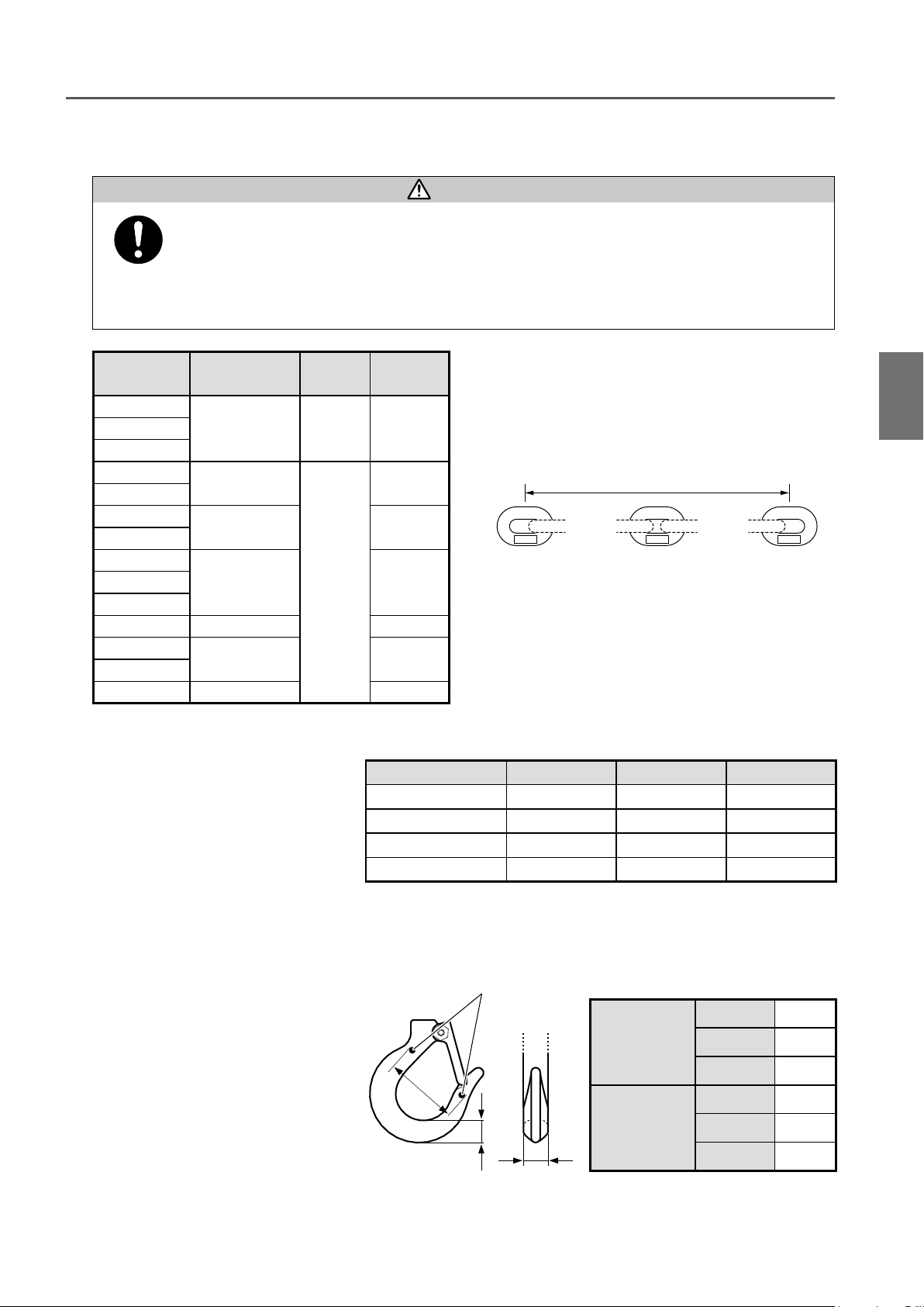
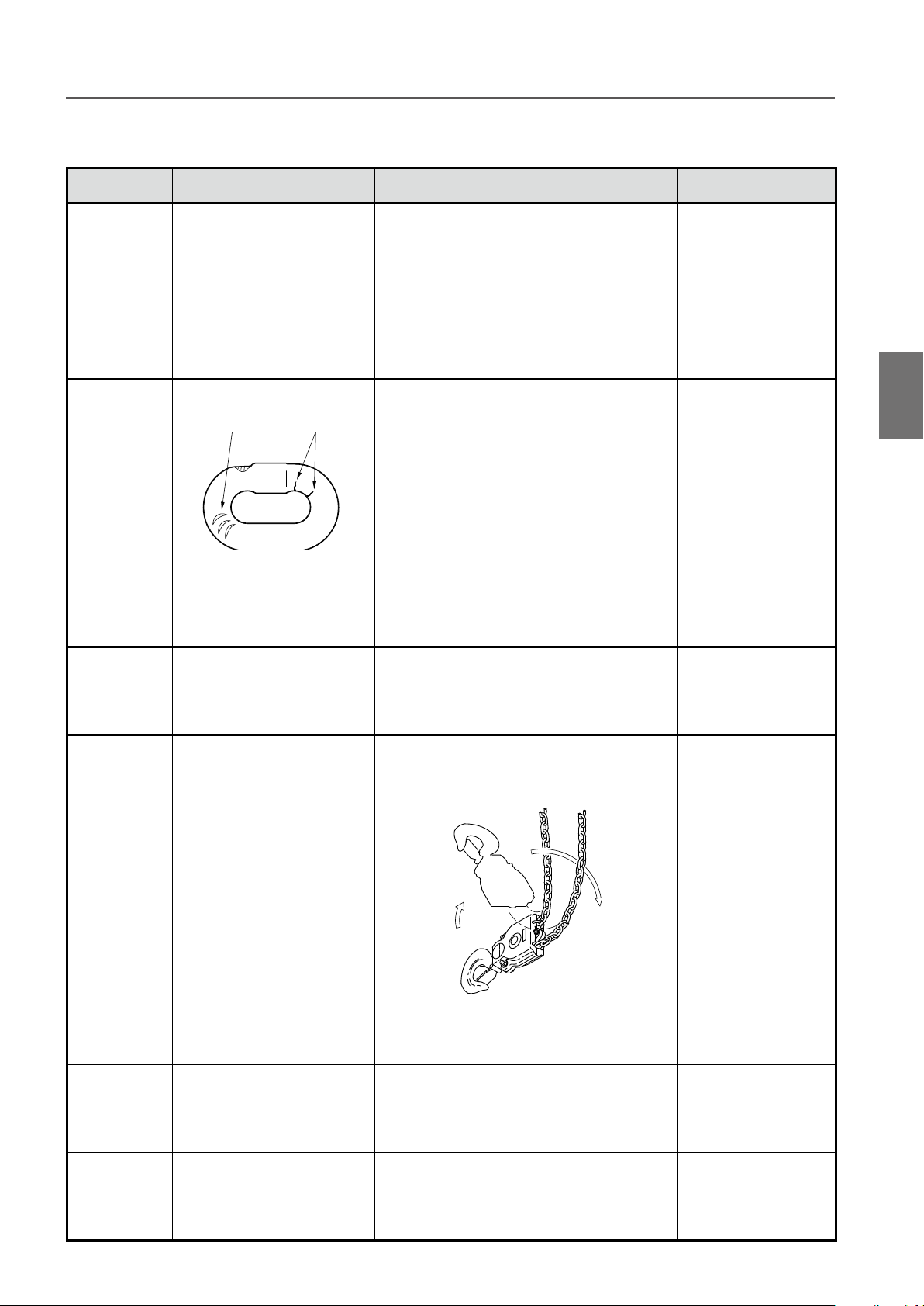
■Checking the Marks
• Be sure to check that the Load Chain has "RH-DAT " or "FT-DAT" mark on it and the chain size is
appropriate for the ER2 model you are using. (See the following table.) The Load Chain of other models
(such as model ES or ER) or different rating cannot be used.
Mandatory
Use of the Load Chain of other model or other rating may result in death or serious injury due to the drop of the lifted
load.
Opening the Package Checking the Marks / Recording the Product No. / Recording the Initial Value
DANGER
The mark (RH-DAT) to indicate the model of the Load
Chain is indicated on it at an equal spacing. Make sure
that the Load Chain is of a chain size (wire diameter)
appropriate for ER2 referring to the table in the left.
RH-DAT 0000 RH-DAT
Front side : RH-DAT
or
FT-DAT
Back side : H-23
Code
ER2-001H/IH/HD
ER2-003H/IH/HD
ER2-003S/IS/SD
ER2-005L/IL/LD
ER2-005S/IS/SD
ER2-010L/IL/LD
ER2-010S/IS/SD
ER2-015S/IS/SD
ER2-020L/IL/LD
ER2-020S/IS/SD
ER2-025S/IS/SD
ER2-028S/IS
ER2-030S/IS/SD
ER2-050S/IS/SD
Load Chain size :
diameter (mm)
4.3 FT-DAT 24 Links
6.0
7.7 20 Links
10.2 16 Links
11.2 12 Links
10.2 16 Links
11.2 12 Links
Mark Mark pitch
RH-DAT
20 Links
■Recording the Product No.
● Fill in the table in the right with
product's Lot No., Serial No.
(described in the product nameplate),
date of purchase and the name of the
sales shop where you purchased the
product.
* When requesting repair or ordering
a chain hoist part, please inform us of these pieces of information together.
Lot No.
Serial No.
Date of purchase
Name of the sales shop
Item
Electric chain hoist
1
Mark pitch
First markSecond mark Second mark
Front side : Original Lot No. of the
Load Chain (4 digits)
Back side : KITO
Motorized trolley Manual trolley
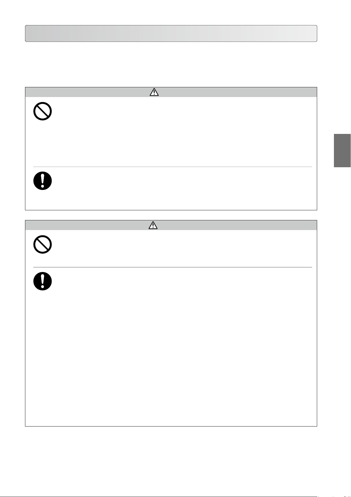
■Recording the Initial
Value
● When opening the package, fill in
the table in the right with the opening
dimension "a" between embossed
marks on the Bottom Hook, the width
of the hook "b" and the thickness of
the hook "c". (These values are used
for checking. Record the value for the
top hook of ER2 when it is used individually.)
Embossed marks
a
Dimensions when the package was opened
Dimension a
Top Hook
(For ER2 only)
c
b
Bottom Hook
Dimension b
Dimension c
Dimension a
Dimension b
Dimension c
mm
mm
mm
mm
mm
mm
15

1
Chapter 1 Handling the Product
Product Specification and Operational Environment
The operational environment of the electric chain hoist and motorized trolley is as follows:
■Standard Specification
Short time ratings : ER2 series(Capacity 100 %) : Single speed model — 60 min.
: MR2 series(Capacity 100 %) : Single speed model — 30 min.
Intermittent ratings : ER2 series(63 % of the capacity) : Single speed model — 60 % ED (at 360 rev/h)
: MR2 series(63 % of the capacity) : Single speed model — 40 % ED (at 240 rev/h)
Product Specication and Operational Environment
Grade * 1 : ISO-M6, M5 or M4, FEM-3m, 2m or 1Am, ASME-H4
Protection : Hoist IP55, Push button IP65
Operation Push button switch operation / 3-Push Button Switch set for hoist only and Manual trolley type / 5- or
7-Push Button Switch set for motorized trolley combined model
Power supply method....Power supply through cabtyre cable
Color...............................KITO Yellow (Equivalent to Munsell 7.2YR6.5/14.5)
Noise level : ER2, single speed 75dB or less (A scale: measured at 1 m away from the Electric chain hoist)
: ER2, dual speed VFD model 80dB or less (A scale: measured at 1 m away from the Electric chain hoist)
: MR2 85dB or less (A scale: measured at 1 m away from the Electric chain hoist)
Braking capacity : 150% of the capacity or more
Other...............................Power Cable length 5 m/10 m (Standard)
Dual speed VFD model (high speed/low speed) — 30/10 min.
Dual speed VFD model (high speed/low speed) — 30/10 min.
Dual speed VFD model (high speed/low speed) — 40/20 % ED
(120/240 rev/h)
Dual speed VFD model (high speed/low speed) — 27/13 % ED
(78/162 rev/h)
Product category
230V Class B
Standard Specication
400V Class F
500V Class B 500V 575V
230/460V Class B
• Operate the electric chain hoist with the rated voltage.
• Do not use the electric chain hoist exceeding the short time ratings and the intermittent ratings.
* Grade
Capacity (kg or t)
125 ER2-001H ER2-001HD
250
500
1
1.5 ER2-015S ER2-015IS/SD
2
2.5 ER2-025S ER2-025IS/SD
2.8 ER2-028S ER2-028IS
3 ER2-030S ER2-030IS/SD
5 ER2-050S ER2-050IS/SD
* For 125kg - 500kg dual speed VFD type equipped with friction clutch with mechanical brake, the grade is ISO M5
16
and FEM 2m.
Motor Insulation
Class
Voltage range
50Hz 60Hz
220V 220V
230V 230V
380V 380V
400V 440V
415V —
208-230V
415-460V
Operating
Voltage
24V
(24V~26.4V)
110V
(110V~121V)
NOTE
Code GRADE Code GRADE
Single speed Dual speed ISO ASME FEM Dual speed ISO ASME FEM
ER2-001IH
ER2-003H ER2-003HD ER2-003IH
ER2-003S ER2-003SD ER2-003IS
ER2-005L ER2-005LD ER2-005IL
ER2-005S ER2-005SD ER2-005IS
ER2-010L ER2-010IL/LD
ER2-010S ER2-010IS/SD
ER2-020L ER2-020IL/LD
ER2-020S ER2-020IS/SD
M5 H4 2m
M4 H4 1Am
M6 H4 3m

●
ISO
ISO 4301 specifies the total operating hour (service life) of gears and bearings according to the loading status. For
example, the total operating hour (service life) of the mechanism when it is constantly applied with the capacity is
1,600 hours for M5. The total operating hour is 6,300 hours when operated with a medium load.
Product Specication and Operational Environment
Loading status
Light M4 M5 M6
Medium M4 M5 M6
Heavy M4 M5 M6
Ultra heavy M4 M5 M6
* Rate of loading
Light : A case where the capacity is rarely applied. Usually the hoist is used with a light load.
Medium : A case where the capacity is applied considerably frequently. Usually the hoist is used with a medium
Heavy : A case where the capacity is applied considerably frequently. Usually the hoist is used with a heavy load.
Ultra heavy : A case where the capacity is applied constantly.
●
ASME HST
Hoist duty class Typical areas of application
H2
H3
H4
• The grade symbols are identical to those of ASME HST-1M. (Performance standard for Electric Chain Hoist)
*
load.
Light machine shop fabricating,
service,and maintenance; loads and
utilization randomly distributed; capacitys
infrequently handled.
General machine shop fabricating,
assembly, storage, and warehousing;
loads and utilization randomly distributed.
High volume handing in steel warehouses,
machine shops, fabricationg plants and
mills, and foundries; manual or automatic
cycling operations in heat treating
and plating; loads at or near capacity
frequently handled.
800 1600 3200 6300 12500 25000
Total operating hour h
Operation time ratings at K=0.65
Unlformly distributed
work periods
Max. on
time, min / hr
7.6 (12.5%) 75 15 100
15 (25%) 150 30 200
30 (50%) 300 30 300
Max. No.
starts / hr
Max. on time from
cold start, min
work periods
Infrequent
Max. No.
of starts
1
Standard Specication
●
FEM
Relation between ISO-and FEM-Denominations
1 Dm 1 Cm 1 Bm 1 Am 2 m 3 m 4 m 5 m
M 1 M 2 M 3 M 4 M 5 M 6 M 7 M 8
Class of operation time
Load
spectrum
1 L1 K
2 L2 0.50<K
3 L3 0.63<K
4 L4 0.80<K
• The grade symbols are identical to those of FEM 9.511.
(Rules for Design of Serial Lifting Equipment: Classification of Mechanisms)
Cubic
mean value
V0.06 V0.02 V0.25 V0.5 V1 V2 V3 V4 V5
T0 T1 T2 T3 T4 T5 T6 T7 T8
Average operation time per day in hours
0.12 0.25 0.5 1 2 4 8 16>16
0.50 – – 1 Dm 1 Cm 1 Bm 1 Am 2 m 3 m 4 m
0.63 – 1 Dm 1 Cm 1 Bm 1 Am 2 m 3 m 4 m 5 m
0.80 1 Dm 1 Cm 1 Bm 1 Am 2 m 3 m 4 m 5 m –
1.00 1 Cm 1 Bm 1 Am 2 m 3 m 4 m 5 m – –
Class of
operating
time
V0.06 T0 0.12 200
V0.12 T1
V0.25 T2
V0.5 T3
V1 T4
V2 T5
V3 T6
V4 T7
V5 T8 >16 50,000
Average
operating
time per day
(in hours)
0.25 400
0.5 800
Calculated
total operating
time
(in hours)
1 1,600
2 3,200
4 6,300
8 12,500
16 25,000
(to be continued)
17

Chapter 1 Handling the Product
Product Specification and Operational Environment (continued)
■Operational Environment
Ambient temperature : -20°C — +40°C
Gradient of rail : No gradient in travel rail (for the hoist with trolley)
Ambient humidity : 85 % or less (no condensation)
Explosion-proof construction : Not applicable to the work environment with explosive gases or explosive vapor
Non-conforming environment : A place with organic solvent or volatile powder, and a place with a plenty of powder
and dust of general substances
: A place with considerable amount of acids and salts
NOTE
Product Specication and Operational Environment
When installing the electric chain hoist outdoors or to the place where the hoist is exposed to direct rain, wind and
snow, shade the hoist with roof to protect it from rain, wind and snow.
1
Operational Environment
18
How to Use
ER2 Series Electric Chain Hoist has two models: single speed model and dual speed VFD model. Other than them,
such products are provided that can travel/traverse when combined with a trolley or a crane. Their push button switches
for operation differ in the size and the operating method. Check the product model of the hoist and use it properly.
Prohibited
Mandatory
Prohibited
DANGER
• Do not use the Hook without a Hook Latch or damaged Hook.
• Do not use the Load Chain with heavy elongation, abrasion or deformation.
• Do not cut, extend, or weld the Load Chain.
• Do not use the Load Chain with the Bottom Hook without smooth motion.
• Do not use the Load Chain when its brake does not function securely even without load, or when the
stopping distance is too long.
• Do not use the product if it moves oppositely to the direction indicated on the push button switch.
Failure to comply with these instructions may result in death or serious injury.
• Carry out daily inspection before operation.
(When any abnormality was found during inspection, turn off the power, indicate “FAILURE" and ask the maintenance
engineer for repair.)
• Check the slinging devices for no abnormality.
Failure to comply with these instructions may result in death or serious injury.
CAUTION
• Do not use the product with an illegible nameplate or warning label affixed to the body size.
Failure to this instruction may result in the injury or the property damage.
How to Use
1
Mandatory
• When using the product for the first time, affix the labels indicating East, West, North and South on the push
button switches.
• Check the contents of the work and make sure that the electric chain hoist has proper performance for the load
and lift.
• Check the contents of the work and operate the electric chain hoist at a place enabling to look out the operating
area without hindrance.
• When looking out the operating area is difficult, arrange the monitor near the place for safety.
• Operate the electric chain hoist at a place with firm foothold without danger of falling, stumbling, slipping or
over turning.
• Before moving the load, warn all the surrounding people.
• Even if the crane or the electric chain hoist is permanently installed and used for the same purpose repeatedly,
check the contents of the work and make sure that the work does not exceed the capacity on each occasion.
• Appoint the maintenance engineer or competent personnel among the qualified personnel for operation of
cranes and electric chain hoists. Indicate the name of the personnel on a place with legibility.
• The maintenance engineers shall check the result of daily inspection.
• When informed of abnormality of the electric chain hoist, the maintenance engineers shall take immediately
any necessary measures such as prohibition of use and repair.
• When carrying out inspection and repair, secure the environment for safe work without electric shock and
falling.
Failure to comply with these instructions may result in bodily injury or property damage.
(to be continued)
19
Chapter 1 Handling the Product
Body
Fan cover
Motor frame
Gear case
Controller cover
How to use (continued)
■Daily Inspection of Electric Chain Hoist (Hook Suspended Type)
DANGER
• Carry out daily inspection before use.
(When any abnormality was found during inspection, turn off the power, indicate “FAILURE" and ask the maintenance
Mandatory
engineer for repair.)
Neglecting to carry out daily inspection may result in death or serious injury.
1
How to UseDaily Inspection of Electric Chain Hoist (Hook Suspended Type)
Refer to the technical material attached in Appendix (P122) for the structure of the product and the name
●
of each part.
■Appearance
Item Check method Criteria When failed
Indication of
nameplates
and labels
Deformation
and damage
of body size
and each part
• Check visually. • No peel off. Indication can be seen clearly.
• Check visually. • Noapparentdeformation,damage,awand
crack
Carry out cleaning, repair
or replace with new
nameplate or label.
When replacing with a
new nameplate or label
is required, please inform
KITO of the description
in “Record of the Product
No." (P17) such as Lot
No. and Serial No.
Replace the parts with
deformation, damage,
flaw or crack.
20
Loosened
or fallen off
bolts, nuts
and split pins
• Check visually or using
tools.
• Bolts, nuts and split pins are fastened
securely.
DANGER
• Even fallen off of a bolt causes
for the body size to drop. Be
Mandatory
sure to check.
Fallen off of a bolt may result in death
or serious injury.
Fasten bolts, nuts and
split pins securely.
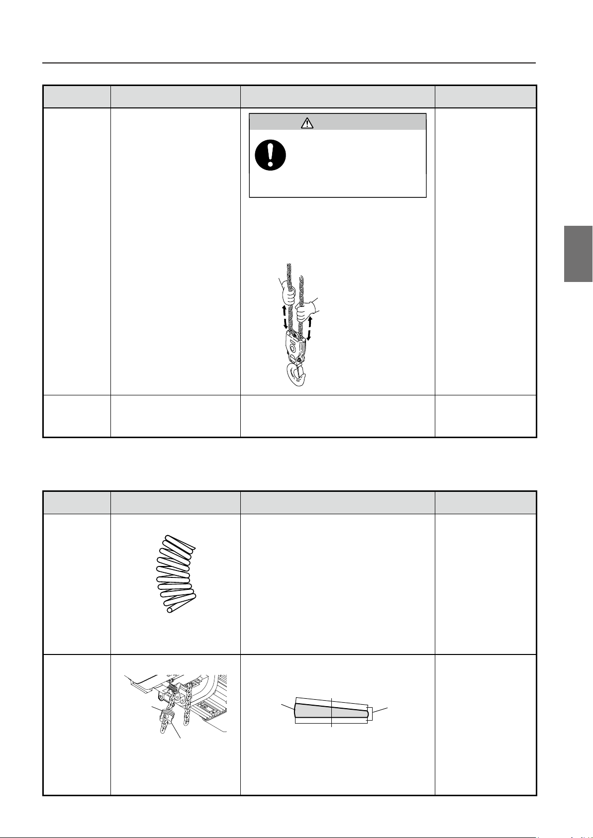
■Load Chain
Item Check method Criteria When failed
Elongation of
Pitch
Abrasion
of Wire
Diameter
Deformation,
Flaw,
Entanglement
Rust,
Corrosion
• Check visually • No apparent elongation Refer to Load Chain
(P69) of Chapter 2,
Frequent inspection.
• Check visually • No apparent abrasion Refer to Load Chain
(P69) of Chapter 2,
Frequent inspection.
• Check visually
Flaw
• Check visually for no foreign
matter such as attached
sputter.
• Check visually • No apparent rust and corrosion Replace the Load
Crack
• No deep notch
• No deformation such as twist
• No attached sputter
• No entanglement
• No crack
Replace the Load
Chain.
Chain.
How to Use Daily Inspection of Electric Chain Hoist (Hook Suspended Type)
1
Twist • Check visually • No capsized link at Bottom Hook of double
type Load Chain
Lubrication • Check visually • To be oiled adequately Apply oil.
Mark • Check visually • Check the mark pitch and the indication. (Refer
to “Checking the Marks" (P17).)
Untwist the Load
Chain.
Replace the Load
Chain.
(to be continued)
21
Chapter 1 Handling the Product
How to use (continued)
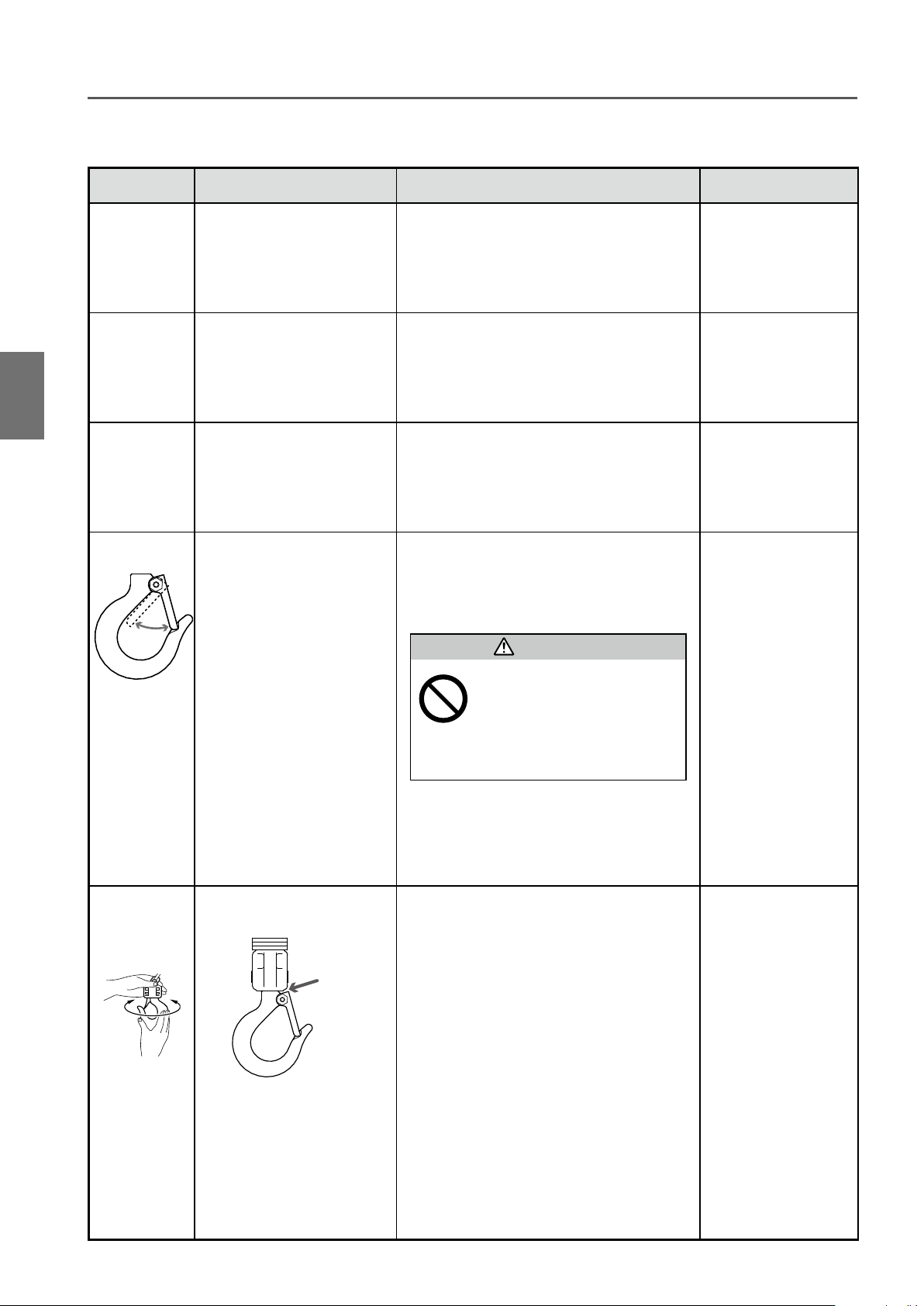
■Top Hook/Bottom Hook
Item Check method Criteria When failed
1
How to UseDaily Inspection of Electric Chain Hoist (Hook Suspended Type)
Opening of
the Hook
Abrasion • Check visually • No apparent abrasion
Deformation,
Flaw,
Corrosion
Hook Latch • Check visually and check
• Check visually • No apparent opening of the Hook
• Check visually • Noapparentdeformation,awandcorrosion
• The Hook Latch is mounted securely inside
the movement of the Hook
Latch.
the Hook opening.
• No deformation. The Hook Latch moves
smoothly.
DANGER
Carry out the
inspection item of Top
and Bottom Hook (P70)
of Frequent inspection.
Carry out the
inspection item of Top
and Bottom Hook (P70)
of Frequent inspection.
Carry out the
inspection item of Top
and Bottom Hook (P70)
of Frequent inspection.
Replace the Hook
Latch.
Hook
movement
(Rotation)
• Check visually and rotate
the Hook by hand.
Neck
• Do not use the Hook without
the Hook Latch.
Prohibited
• No apparent gap between the Bottom Yoke
and the shank (at the neck).
• The Bottom Yoke rotates in both directions
equally.
• The Bottom Yoke rotates smoothly.
Use of the Hook without the Hook
Latch may result in death or serious
injury.
Replace the Hook.
22
Item Check method Criteria When failed
Movement
of the Idle
Sheave
Bottom Yoke • Check visually. • No loosened bolt or nut
• Check the Idle Sheave by
moving
CAUTION
• When chec king, wear gloves
and be careful for your finger
Mandatory
• The Idle Sheave rotates smoothly.
* The Idle Sheave does not rotate smoothly
when bearing is damaged or sheave shaft is
deformed.
• The Load Chain moves smoothly.
not to be caught.
Otherwise it may result in injury.
Move the Load Chain
by hand.
Replace the bearing of
the Idle Sheave.
How to Use Daily Inspection of Electric Chain Hoist (Hook Suspended Type)
1
Attach the Bottom Hook to
the Load Chain securely.
■Peripheral parts of the body size
Item Check method Criteria When failed
Chain Spring • Check visually • No apparent shrinkage or compression Carry out the
inspection item of
Chain Spring (P77) of
Periodic inspection.
Cushion
Rubber
• Check visually
Cushion
Rubber
Stopper
• No apparent shrinkage or compression
• No peel off, crack of deformation of rubber
Rubber
Steel plate
Replace the Cushion
Rubber.
(to be continued)
23
Chapter 1 Handling the Product
How to use (continued)
■Push Button Switch
Item Check method Criteria When failed
1
How to UseDaily Inspection of Electric Chain Hoist (Hook Suspended Type)
Switch body
size
• Check visually • No deformation, damage and no loosened
screw
• Label indication of the push button switch can
be seen clearly.
Clean and repair the
label or replace with
a new label. Affix the
label securely.
■Function and Performance
Check the following item with no load.
●
Item Check method Criteria When failed
Operational
Check
• Press the push button and
check each operation.
• The Load Chain can be wound smoothly.
• The Electric chain hoist moves in the same
direction as that of the push button operation.
• When the operation is stopped, the motor
stops immediately.
• When the Emergency Stop Button is pressed,
all hoist motions stop.
• When operating other push button while the
Emergency Stop Button is pressed, the hoist
does not start operation.
• When canceling the Emergency Stop Button,
the hoist operates normally.
Refer to Chapter 3
“Guidance on
Troubleshooting" (P94
to 97).
Brake • Press the push button and
check the operation of the
Brake.
Friction
Clutch with
Mechanical
Brake
Limit Switch • Press the push button and
Check for no
Abnormal
Sound
• Press the push button and
check the operation of the
Friction Clutch.
check the operation of the
Limit Switch.
• Press the push button and
check the operation.
NOTE
Sound is also an important
che c k point. A l w a y s be
careful for the noise of the
electric chain hoist.
• When stopping the operation, the Brake is
applied immediately and the Bottom Hook
shall stop immediately.
(Guideline: The travel of the Load Chain is
within 2 to 3 links.)
• When lifting, the sound of pawl clicks regularly.
(Forthefrictionclutchofstandardspecication
makes no pawl sound.)
• When the hoist is operated to the upper or
lower limit, the motor automatically stops.
• No abnormal sounds and vibrations Replace the abnormal
• No popping sound from the Load Chain. Check the Load Chain.
Carry out the inspection in
accordance with the items
in Chapter 2 “Periodic
inspection" Electromagnetic
Brake (P79).
Disassemble the
Friction Clutch and to
check.
Replace the Limit Switch.
Disassemble the actuator
of the Limit Switch to
clean.
part.
Apply oil on the Load
Chain.
(Refer to P21.)
24
■Daily Inspection of Motorized Trolley (MR2)
■Appearance
Item Check method Criteria When failed
Indication of
Nameplates
and Labels
Deformation
and damage
of each part
Motor cover
• Check visually • No peel off. Indication can be seen clearly. Clean and repair the
label or replace with a
new label.
• Check visually • No apparent deformation, damage and
corrosion
Connection Box
Replace the deformed
or damaged part.
How to Use Daily Inspection of Motorized Trolley (MR2)
1
Loosened
or fallen off
bolts, nuts
and split pins
FrameMotor frame
• Check visually or using
tools.
• Bolts, nuts and split pins are fastened
securely.
DANGER
• Even a drop off of a split pin
may cause of drop of the body
Mandatory
size. Be sure to check it.
Drop off of split pin may result in death
or serious injury.
Fasten bolts, nuts and
split pins securely.
(to be continued)
25

Chapter 1 Handling the Product
How to use (continued)
■Function and Performance
Check the following item with no load.
●
Item Check method Criteria When failed
How to Use
1
Operational
Check
Brake • Press the push button to
• Press the push button to
check the operation.
check the operation of the
Brake.
• To travel smoothly. No meandering and
vibration.
• The electric chain hoist moves in the same
direction as that of the push button operation.
• When the operation is stopped, the motor
stops immediately.
• When the Emergency Stop Button is pressed,
all hoist motions stop.
• When operating other push button while the
Emergency Stop Button is pressed, the hoist
does not start operation.
• When canceling the Emergency Stop Button,
the hoist operates normally.
• When the operation is stopped, the Brake is
applied and the motor stops immediately.
■Daily Inspection of Manual Trolley (TSG/TSP)
Refer to Chapter 3
“Guidance on
Troubleshooting" (P94
to 97).
Carry out the inspection
in accordance with the
items in Chapter 2
“Periodic inspection"
Electromagnetic Brake
(P84).
■Appearance
Item Check method Criteria When failed
Indication of
Nameplates
and Labels
Deformation
and damage
of each part
Loosened
or fallen off
bolts, nuts
and split pins
Daily Inspection of Motorized Trolley (MR2) / Daily Inspection of Manual Trolley (TSG/TSP)
• Check visually • No peel off. Indication can be seen clearly. Clean and repair the
label or replace with a
new label.
• Check visually • No apparent deformation and corrosion
• No apparent deformation on the Frame
• Check visually or using
tools.
• Bolts, nuts and split pins are fastened
securely.
Replace the deformed
or damaged part.
Fasten bolts, nuts and
split pins securely.
DANGER
• Even a drop off of a split pin
may cause of drop of the body
Mandatory
size. Be sure to check it.
Drop off of split pin may result in death
or serious injury.
26

■Function and Performance
Check the following item with no load.
●
Item Check method Criteria When failed
Operational
Check
• Check the traveling motion
of the electric chain hoist by
moving it manually.
• To travel smoothly. No meandering and
vibration.
Carry out Chapter 2
"Periodic inspection".
How to Use Daily Inspection of Manual Trolley (TSG/TSP)
1
(to be continued)
27
Chapter 1 Handling the Product
How to use (continued)
■How to Operate the Push Button Switches
CAUTION
• Do not hang the Push Button Switch Cord on other object, or pull the cord strongly.
• Do not use the Push Button Switch if its button does not operate smoothly.
Prohibited
• Do not bundle or tie the cord for the adjustment of its length.
Failure to comply with this instruction causes bodily injury or loss of property.
How to UseHow to Operate the Push Button Switches
Mandatory
• When taking hand off the Push Button Switch after operation, do not throw it. Be careful not to hit other
worker with the Push Button Switch.
Failure to comply with this instruction causes bodily injury or loss of property.
1
If the Electric chain hoist is tripped due to overheat of the VFD, the VFD cannot be reset soon after the trip. Reset the VFD
after a while.
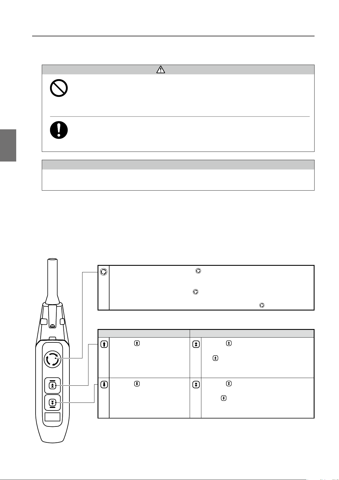
■3-Push Button Switch Set
3-Push Button Switch Set is equipped with a lock type emergency stop button (VFD reset button) and lift/lower push
buttons. One-step push button switch or two-step push button switch is mounted as Lift/lower push button switches
in accordance with the specification of single speed or dual speed VFD specification. Refer to the operation method
of the corresponding specification.
●
Emergency Stop Button (VFD Reset Button)
1) Press the Emergency Stop Button deeply when carrying out an emergency stop or
VFD reset.
• The button is locked at the pressed end.
2) Turn the Emergency Stop Button clockwise to cancel the lock.
• Press-locked button returns to the original position.
* When the electric chain hoist is not used, press the Emergency Stop Button
NOTE
deeply to the end.
28
●
Operation Button
● Lift/Lower Button
Single Speed Model Dual Speed VFD Model
1) Press button to lift the
load.
• The electric chain hoist stops
when the button is released.
1) Press button to lower the
load.
• The electric chain hoist stops
when the button is released.
1) Press button to lift the load.
2) When lifting the load at high speed, press the
button further to the end.
• The electric chain hoist stops when the button is
released.
1) Press button to lower the load.
2) When lowering the load at high speed, press
the
button further to the end.
• The electric chain hoist stops when the button is
released.

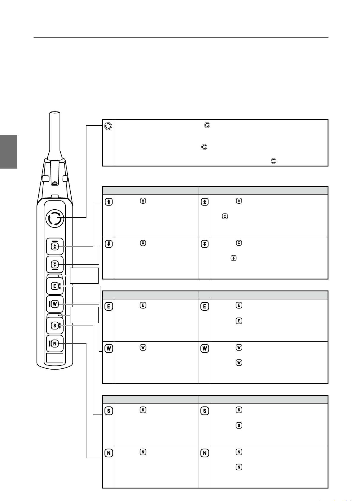
■5-Push Button Switch Set
5-Push Button Switch Set is equipped with a lock type emergency stop button (VFD reset button) and lift/lower push
buttons. One-step push button switch or two-step push button switch is mounted as Lift/lower push button switches
in accordance with the specification of single speed or dual speed VFD specification. Refer to the operation method
of the corresponding specification.
Moving direction of the trolley is expressed as East/West for traveling motion in the operational instruction of the
Push Button Switch Set.
●
Emergency Stop Button (VFD Reset Button)
1) Press the Emergency Stop Button deeply when carrying out an emergency stop or
VFD reset.
• The button is locked at the pressed end.
2) Turn the Emergency Stop Button clockwise to cancel the lock.
• Press-locked button returns to the original position.
* When the electric chain hoist is not used, press the Emergency Stop Button
●
Operation Button
● Lift/Lower Button
Single Speed Model Dual Speed VFD Model
deeply to the end.
How to Use How to Operate the Push Button Switches
1
Dual
No label for the
single speed
model
1) Press button to lift the
load.
• The electric chain hoist stops
when the button is released.
1) Press button to lower the
load.
• The electric chain hoist stops
when the button is released.
● Travel Button
Single Speed Model Dual Speed VFD Model
1) Press button to move the
trolley to the east.
• The trolley stops when the
button is released.
1) Press button to move the
trolley to the west.
• The trolley stops when the
button is released.
1) Press button to lift the load.
2) When lifting the load at high speed, press the
button further to the end.
• The electric chain hoist stops when the button is
released.
1) Press button to lower the load.
2) When lowering the load at high speed, press
the
button further to the end.
• The electric chain hoist stops when the button is
released.
1) Press button to move the trolley to the
east at low speed.
2) Press
button further to the end to move
the trolley to the east at high speed.
• The trolley stops when the button is released.
1) Press button to move the trolley to the
west at low speed.
2) Press
button further to the end to move
the trolley to the west at high speed.
• The trolley stops when the button is released.
(to be continued)
29
Chapter 1 Handling the Product
How to use (continued)
■7-Push Button Switch Set
7-Push Button Switch Set is equipped with a lock type emergency stop button (VFD reset button) and lift/lower push
buttons. One-step push button switch or two-step push button switch is mounted as Lift/lower push button switches
in accordance with the specification of single speed or dual speed VFD specification. Refer to the operation method
of the corresponding specification.
Moving directions of the trolley are expressed as East/West for traveling motion, and North/South for traversal
motion in the operational instruction of the Push Button Switch Set.
●
Emergency Stop Button (VFD Reset Button)
How to UseHow to Operate the Push Button Switches
1) Press the Emergency Stop Button deeply when carrying out an emergency stop or
VFD reset.
• The button is locked at the pressed end.
2) Turn the Emergency Stop Button clockwise to cancel the lock.
1
●
Operation Button
• Press-locked button returns to the original position.
* When the electric chain hoist is not used, press the Emergency Stop Button
● Lift/Lower Button
Single Speed Model Dual Speed VFD Model
1) Press button to lift the
load.
• The electric chain hoist stops
when the button is released.
1) Press button to lower the
load.
• The electric chain hoist stops
when the button is released.
Dual
No label for the
single speed
model
● Travel Button
Single Speed Model Dual Speed VFD Model
deeply to the end.
1) Press button to lift the load.
2) When lifting the load at high speed, press the
button further to the end.
• The electric chain hoist stops when the button is
released.
1) Press button to lower the load.
2) When lowering the load at high speed, press
the
button further to the end.
• The electric chain hoist stops when the button is
released.
30
Dual
No label for the
single speed
model
1) Press button to move the
trolley to the east.
• The trolley stops when the
button is released.
1) Press button to move the
trolley to the west.
• The trolley stops when the
button is released.
● Traverse Button
Single Speed Model Dual Speed VFD Model
1) Press button to move the
trolley to the south.
• The trolley stops when the
button is released.
1) Press button to move the
trolley to the north.
• The trolley stops when the
button is released.
1) Press button to move the trolley to the
east at low speed.
2) Press
button further to the end to move
the trolley to the east at high speed.
• The trolley stops when the button is released.
1) Press button to move the trolley to the
west at low speed.
2) Press
button further to the end to move
the trolley to the west at high speed.
• The trolley stops when the button is released.
1) Press button to move the trolley to the
south at low speed.
2) Press
button further to the end to move
the trolley to the south at high speed.
• The trolley stops when the button is released.
1) Press button to move the trolley to the
north at low speed.
2) Press
button further to the end to move
the trolley to the north at high speed.
• The trolley stops when the button is released.
 Loading...