

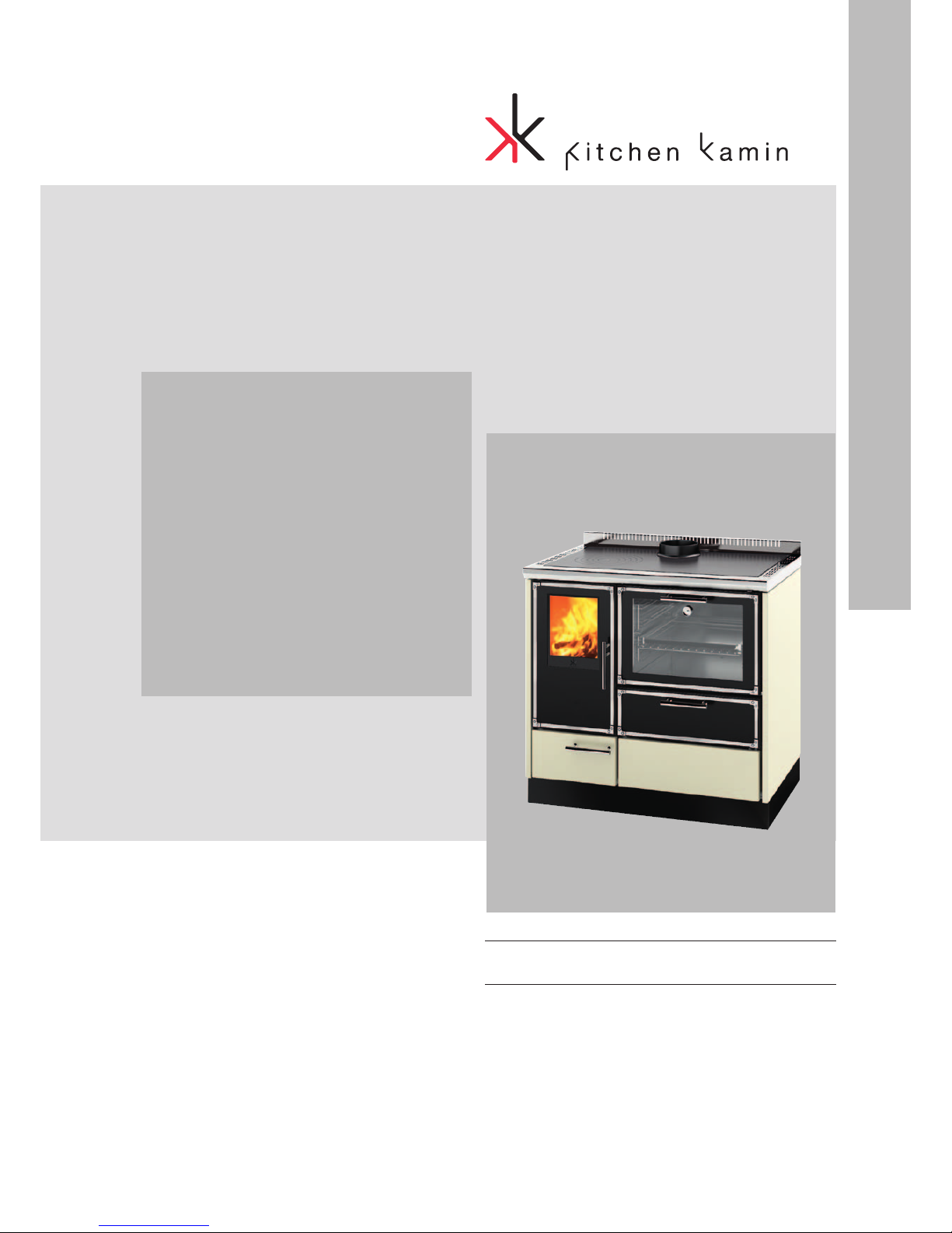
Kitchen Kamin KE 90 H 20, KE 90 H 14 Installation, Use And Maintenance Manual
UK Installation, use and maintenance
Ke 90 h
Wood BurnInG
THErmo-CooKEr

2
ENGLISH
TABLE OF CONTENTS
Introduction 3
Safety information 4
General information 5
Installation 9
Instructions for use 14
Maintenance 17
In the event of problems 19
The undersigned with head office headquarters at Via Vincenzo
Monti 47 - 20123 Milan - Italy - VAT IT00192220192
Declares under its own responsability as follows:
The below listed wood burning coockers comply with EU
Regulation 305/2011 and the harmonized European Standard
EN 12815:2001 + A1:2004 + AC:2007
Wood thermocoocker tradename KITCHEN KAMIN
denominated KE 90 H 14 and KE 90 H 20
n° of manufacture: Ref. Data nameplate
KE 90 H 14 Declaration of Performance (DoP EK n°149
)
KE 90 H 20 Declaration of Performance (DoP EK n°151)
Ref. Data nameplate
The liability is limited to the product supply only.
3
ENGLISH
Dear Sir/Madam
Congratulations on choosing our product. Before you use it,
please read this manual carefully, to get the best from your
new appliance in total safety.
This manual is an integral part of the product. Please keep it
for the entire life of the product. If you lose it, you can request
a copy the dealer.
After unpacking the product, check the condition and
completeness of the contents.
In the event of error, immediately contact the retailer where
the purchase was made, providing him with a copy of the
warranty booklet and the sales receipt.
The appliance must be installed and operated in compliance
with local and national law and European regulations. For the
installation, and for anything not specifically indicated in the
manual, observe local regulations.
The diagrams in this manual are illustrative; they do not
always refer specifically to your product and are not binding
in any way.
The product is uniquely identified by a number, the
“counterfoil”, which is indicated on the warranty certificate
inside the product.
Please keep:
• the warranty certificate accompanying the product
• the purchase receipt given to you by the retailer
• the declaration of conformity given to you by the installer.
The warranty conditions are given in the warranty certificate
accompanying the product.
SYMBOLS
Some parts of the manual use the following symbols:
INFORMATION:
Failure to follow these instructions could
compromise correct product use.
CAUTION:
Read carefully the message to which this
refers, as failure to do so may result in
serious damage to the product and may
endanger the safety of people using it.

4
ENGLISH
For reasons of safety, read the
user instructions included in this
manual.
NEVER OPERATE THE BOILER
WITHOUT WATER IN THE CIRCUIT.
A “DRY” IGNITION COULD
RESULT IN DAMAGE TO THE
BOILER.
SAFETY INFORMATION
• The product was not designed for use by people,
including children, whose physical, sensory or
mental capacities are reduced.
• The product was designed to burn dry wood in the
quantities and methods described in this manual
• The product was designed for internal use and in
premises with normal humidity
• The product must be installed in premises where
there is no danger of fire.
• In the event of fire, call the competent authorities.o
not extinguish the fire with water jets
The safety risks can be caused, among other things,
by:
• contact with the fire and hot parts (e.g. glass
and piping). DO NOT TOUCH HOT PARTS and,
with the product off but hot, always use the glove
supplied. Otherwise you risk getting burnt
• use of unsuitable products for lighting (e.g.
alcohol). DO NOT LIGHT OR RE-LIGHT THE
FLAME WITH LIQUID SPRAY PRODUCTS OR
FLAMETHROWERS. You risk getting seriously
burned and causing damage to property and
people.
• use of fuel other than dry wood. DO NOT BURN
RUBBISH, PLASTIC OR ANYTHING OTHER THAN
DRY WOOD IN THE FIREPLACE. You risk dirtying
the product, fires in the chimney flue and causing
damage to the environment.
• use of fuel different from the recommended fuel.
DO NOT OVERLOAD THE FIREPLACE. There
is a risk of deformation with risks for people in
the event of attemptedfixing up and irreversible
changes to the colour of the paint on the metal
parts. The retailer cannot be held liable.
• cleaning the hot fireplace. DO NOT EXTRACT
HOT. You risk compromising the extractor and,
possibly, smoke in the environment
• cleaning of the smoke channel with various
substances. DO NOT CLEAN WITH FLAMMABLE
PRODUCTS. There is a risk of fires, back draft.
• cleaning of the hot glass with unsuitable products.
DO NOT CLEAN THE HOT GLASS WITH WATER
OR SUBSTANCES OTHER THAN GLASS
CLEANERS RECOMMENDED OR DRY CLOTHES.
There is a risk of cracks in the glass as well as
permanent, irreversible damage to the glass
• deposit of inflammable materials under the safety
distance indicated on this manual. DO NOT REST
LINEN ON THE Product DO NOT POSITION
THE CLOTHES HORSE AT DISTANCES UNDER
THOSE CONSIDERED SAFE. Keep any form of
inflammable liquid far from the appliance in use.
There is a risk of fire.
• blocked opening of the air vents in the premises
or air input. DO NOT BLOCK THE AIR VENT
OPENINGS OR BLOCK THE CHIMNEY FLUE.
There is a risk of a back draft in the room which
could damage property and people.
• use of the product as a support or ladder (DO
NOT CLIMB ON THE PRODUCT OR USE IT AS
A SUPPORT). You risk damaging property and
people.
• use of the product with the fireplace open. DO
NOT USE THE Product WITH THE DOOR OPEN.
• addition of fuel and door opening approaching
the fire with flammable and loose clothing. Do
NOT open the door or approach the glass with
flammable, wide clothing whose ends could catch
fire
• open the door with incandescent material exiting.
Do NOT throw incandescent material out of the
product. You risk a fire
Lastly, do not act on your own initiative, but contact the
retailer or installation technician.
5
ENGLISH
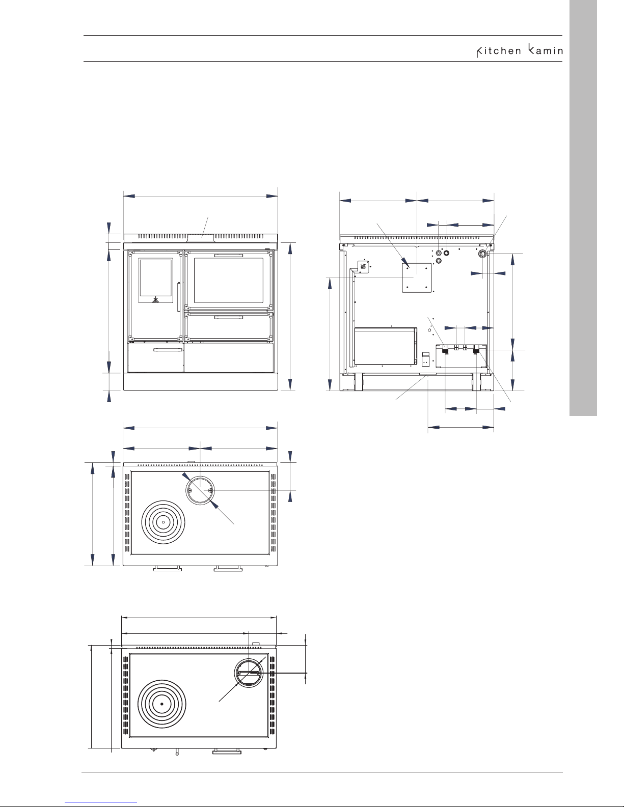
GENERAL INFORMATION
KE 90 H - DIMENSIONS (cm)
- fireplace dimensions L 25 x P 39 x H 40 cm
- internal dimensions of oven 41 x 42,5 x 29,5 cm , capacity 50 l
- cast iron cook top with 25 cm removable rings : 80 x 48 cm *
- cast iron cook top with 28 cm removable rings : 80 x 48 cm **
- glass cooktop : 80 x 48 cm
NOTE
• For open expansion vessel installations use the M1
delivery at the top.
• No loading/unloading connections are required.
• To install the product in a closed expansion vessel
system, check local regulations, then fit a thermal
discharge valve to the safety coil and connect the
coil’s delivery and return as required by the regulations
themselves
mandata vaso
aperto 1" F
presa aria
mandata vaso
chiuso 1" M
ritorno 1" M
56
B
C
E
D
esterna Ø 10 cm
45
7
2
2,5
uscita fumi Ø 15 cm
10
72
4
5
90
86
38,5
11
16
14
45
66
24
A
8,5
uscita fumi Ø 15 cm
mandata vaso
aperto 1" F
presa aria
mandata vaso
chiuso 1" M
ritorno 1" M
56
B
C
E
D
A= pozzetto con bulbo della sonda di
regolazione aria ½" F (già installato)
B= predisposizione per pozzetto per sonda
della valvola di scarico termico ½" F
C= predisposizione per pozzetto per sonda
lettura acqua di caldaia ½" F
D= ritorno serpentina ½" M
E= mandata serpentina ½" M
esterna Ø 10 cm
45
7
2
2,5
uscita fumi Ø 15 cm
10
72
4
5
90
86
38,5
11
16
14
45
66
24
A
8,5
60
58
2
45 45
90
16
uscita fumi Ø 15 cm
uscita fumi Ø 15 cm
Smoke outlet Ø 15 cm
Combustion air Ø 10 cm
A = sump with air regulation sensor bulb already
installed 1/2“ F
B = fitting for thermal discharge valve sensor sump
1/2“ F
C = fitting for boiler water sensor sump 1/2“ F
D = thermal relief coil return 1/2“ M
E = thermal relief coil flow 1/2“ M
Smoke outlet Ø 15 cm
Smoke outlet Ø 15 cm
return 1” M
flow open-tank
1” F
flow closed-tank
1” M
**
2
58
60
90
74 16
16
*
Smoke outlet Ø 15 cm
6
ENGLISH
The manufacturer reserves the right to modify the product at his own discretion and wi-
thout notication.
The above data are illustrative and are drawn from the certifi cation by a notifi ed body.
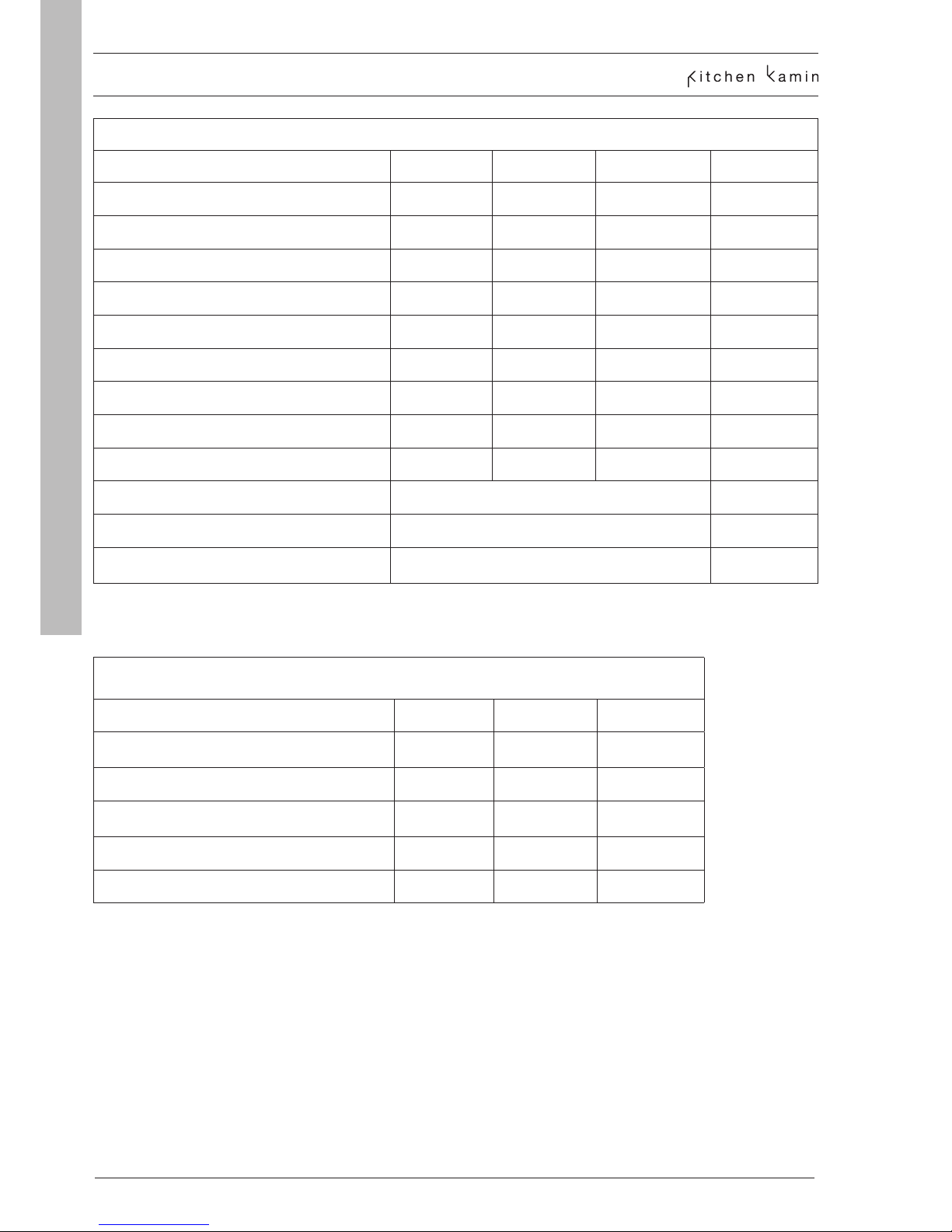
GENERAL INFORMATION
* The heating volume is calculated with the heat request of 33 Kcal/m³ hour
TECHNICAL CHARACTERISTICS according to EN 12815
KE 90 H 20 KE 90 H 14 KE 90 H 14
Nominal power Nominal power Reduced Power
Power output 20,3 14,2 7 kW
Potenza utile all’acqua 13,8 8,3 4,8 kW
Efficiency 70,8 80,1 77,2 %
Emissions CO 13% O
2
0,778 0,107 0,129 %
Fume temperature 265 237 201 °C
Draught 12 12 12 Pa
Fuel consumption 6,2 3,9 2 kg/h
Heatable volume * 530 370 195 m
3
Smoke outlet pipe diameter (male) 150 mm
Air intake pipe diameter (male) 100 mm
Weight including packaging
260 kg
TECHNICAL DATA FOR THE DIMENSIONING OF THE FLUE
KE 90 H 20 KE 90 H 14
Nominal
power
Nominal
power
Power output 20,3 14,2 kW
Temperature of fumes on exit from the discharge
pipe
318 284 °C
Minimum draught 10 10 Pa
Fume flow capacity 23,7 13,6 g/s
 Loading...