

4~. &ilkIn
Refrigerator
\nstajjer: Leave
\nstp.pc$ons with the Homeowner.
Homeowner: Keep Insta\latiOn
jnstmctions for future reference.
Save Installation Instructions for
local electrical inspector’s use.
Installation
Before you start...
Proper install&ion is your
responsibility. Make sure you have
everything necessary for correct
installation. It is the responsibility of
the installer to comply with the
installation specifications provided.
The built-in refrigerator weighs over
600 pounds. The floor must be
sturdy enough to support this weight
‘plus the additional weight of door
panels, food and ice.
Grounded electrical outlet is
required. See Electrical
requirements.
Location of the bui!t-in refrigerator
must permit the doors to open to
at least 90°.
Because of the weight and size of
the built-in refrigerator, two or more
people are needed to move and
safely install it.
Dimensions that are shown must
be used. Given dimensions provide
required 0” clearance.
One inch of space is required
between side of refrigerator and a
corner wall-to allow the door to open
to at least a 90° angle.
Electrical Shock Hazard
It is the customer’s responsibility:
m To contact a qualified electrical
installer.
9 To assure that the electrical
installation is adequate and In
conformance with National
Electrical Code, ANSVNFPA 70latest editlon, and all local
codes and ordinances.
Failure to do so could result in
electrical shock or other personal
injury.
Electrical Shock Hazard
Special care must be taken
when drilling holes into the
wall of the house. Electrical
wires may be concealed
behind wall covering.
Personal Injury Hazard
l
Because of the weight and
size of the built-in
refrigerator, two or more
people are needed to move
and safely install it.
9 Most of the refrigerator’s
weight is at the top. Extra
care is needed when
moving the refrigerator to
prevent tipping.
Failure to do so could
result in personal injury
Floor Damage
Keep cardboard shipping piece
or plywood under refrigerator
until it is installed in operating
posltion.
Failure to do so maycause
damage to floor covering.
I
I
Important: Observe all
governing codes and
ordinances.
Failure to meet codes and
ordinances could lead to
fire or electrical shock
hazard.
Tools and
materials needed
for installation:
Phillips screwdrlver
5llB”and 314” socket
and ratchet
114” copper tubing
tubing cutler
appliance dolly
l/s” Allen wrench
adjustable wrench
cardboard or plywood
6, #6, or larger wood
screws
2, wood boards -
32” long (See page
7 for specifications.)
I - 3/W open wrench -
front leveler
stepladder
wrench set
knlfe
3116” and 114”
drill bits
drill
screwdriver
level
bucket
shutoff valve
stud locator
114” nut driver
Parts supplied for installati.on:
top grille assembly
base grille
lube assembly
misc. parts bag
ice-maker bin assembly
Remove parts from packages.
Check that all parts were included.
Parts that must be
ordered separately
or custom-made:
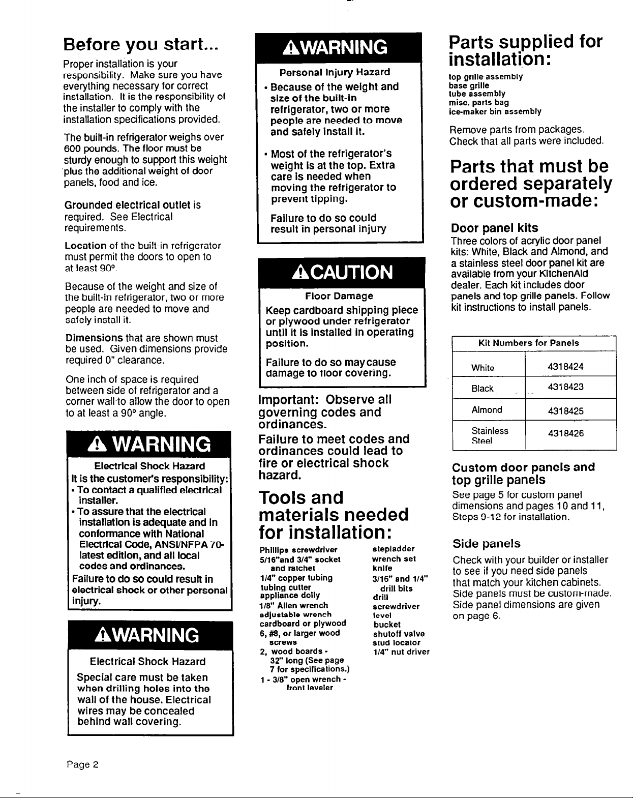
Door panel kits
Three colors of acrylic door panel
kits: White, Black and Almond, and
a stainless steel door panel kit are
available from your KitchenAid
dealer. Each kit includes door
panels and top grille panels. Follow
kit instructions to install panels.
Kit Numbers for Panels
I
I
1
Almond
I
Stainless
Steel
Custom door panels and
top grille panels
See page 5 for custom panel
dimensions and pages 10 and 11,
Steps
9-12
for installation.
Side panels
Check with
to see if you need side panels
that match your kitchen cabinets.
Side panels must be custom-made.
Side panel dimensions are given
on page 6.
your builder or installer
I
4318425
4318426
I
Page 2
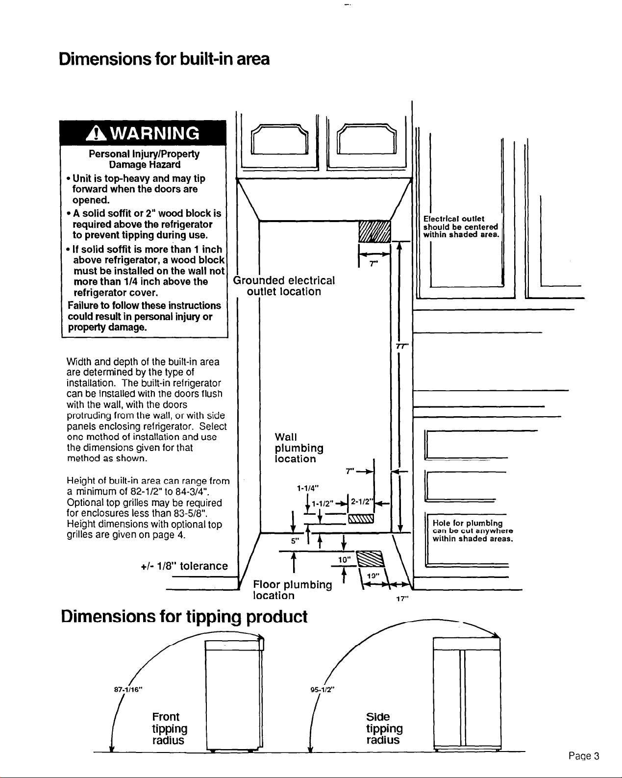
Dimensions for built-in area
Personal Injury/Property
Damage Hazard
l
Unit is top-heavy and may tip
forward when the doors are
opened.
l
A solid soffit or 2” wood block is
required above the refrigerator
to prevent tipping during use.
l
If solid soffit is more than 1 inch
above refrigerator, a wood block
must be installed on the wall noi
more than l/4 inch above the
refrigerator cover.
Failure to follow these instructions
could result in personal injury or
property damage.
Width and depth of the built-in area
are determined by the type of
installation. The built-in refrigerator
can be installed with the doors flush
with the wall, with the doors
protruding from the wall, or with side
panels enclosing refrigerator. Select
one method of installation and use
the dimensions given for that
method as shown.
lrll
ii
irounded electrical
outlet location
Wall
plumbing
location
Electrical outlet
should be centered
within shaded area.
Height of built-in area can range from
a minimum of 82-l/2” to 84-3/4”.
Optional top grilles may be required
for enclosures less than 83-58”.
Height dimensions with optional top
grilles are given on page 4.
+I- 118” tolerance
7yygJ
Floor plumbing
location
Dimensions for tipping product Dimensions for tipping product
87-l/16”
Front
tipping
radius
c
95-112” 95-112”
Side Side
tipping tipping
radius radius
can be cut anywhere
wilhin shaded areas.
L L d d
Page 3
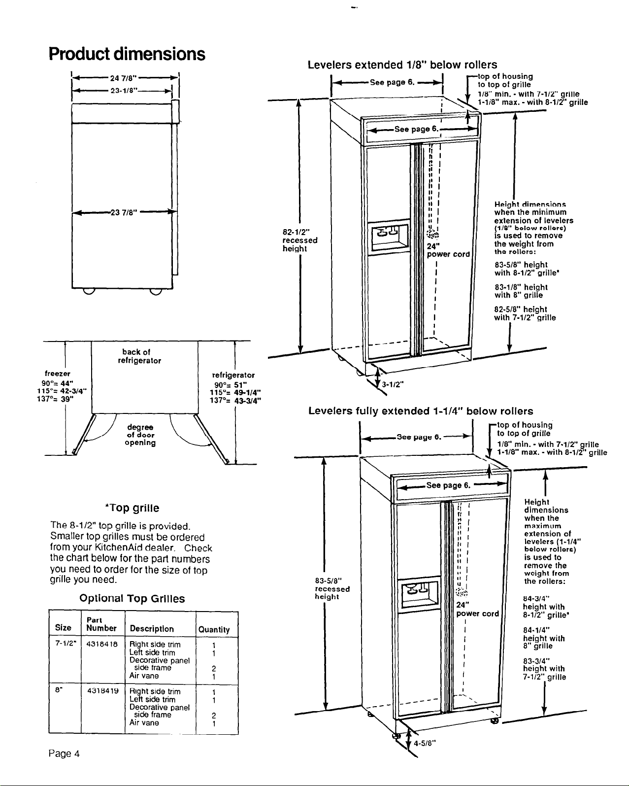
Product dimensions
I- 24 718” -
I-
4
23 718”
v
l L-
v’
Levelers extended 118” below rollers
-See page 6.
i
-See page 6.;
82-112”
ret’
es5
led
heil
ghl
lop ol housing
lo lop of grille
118” min. - with 7-112” grille
1-li8” max. -with 8-W” grille
-1
Height dimensions
when the minimum
extension of levelers
/;‘u”,~:“,“,;;~?2:‘b’:,“’
the weight lrom
the rollers:
83.5/8” height
with 8-112” grille’
83-118” height
with 8” grille
82.5/8” height
with 7-112” grille
back of
refrigerator
freezer
90% 44”
115% 42-314”
137% 39”
*Top grille
The 8-l/2” top grille is provided.
Smaller top grilles must be ordered
from your KitchenAid dealer. Check
the chart below for the part numbers
you need to order for the size of top
grille you need.
Optional Top Grilles
Size
7-l/2’
8”
Part
Number
4318418
4318419 R&h;izt;Gm ;
Description
Right side trim
Left side trim
Decorative panel
side frame
Air vane
Decorative panel
side frame
Air vane
refrigerator
90% 51”
115% 49-l/4”
137% 43-34”
Quantity
;
2
1
2
1
J-
Levelers fully extended l-1/4” below rollers
83-518”
rl
ssed
h
ht
--See page 6. d
118” min. -with 7-W” grille
Height
dimensions
when the
maximum
extension of
levelers (l-114”
below rollers)
is used lo
remove the
weight lrom
the rollers:
84-314”
height with
8-l/2” grille’
- with 8-W’ grille
I
Page
\ 4-518”
4
t
 Loading...