

Page 1
30" (76.2 CM) AND 36" (91.4 CM) RANGE HOOD
Installation Instructions and Use & Care Guide
HOTTE D’ASPIRATION DE 30" (76,2 CM)
ET 36" (91,4 CM)
Instructions d’installation et Guide d’utilisation et d’entretien
Table of Contents/Table des matières.............................................................................2
IMPORTANT: READ AND SAVE THESE INSTRUCTIONS.
IMPORTANT : LIRE ET CONSERVER CES INSTRUCTIONS.
IMPORTANT:
Installer: Leave installation instructions with the homeowner.
Homeowner: Keep installation instructions for future reference.
Save installation instructions for local electrical inspector's use.
IMPORTANT :
Installateur : Remettre les instructions d'installation au propriétaire.
Propriétaire : Conserver les instructions d'installation pour référence ultérieure.
Conserver les instructions d'installation pour consultation par l'inspecteur local des installations électriques.
427500564/9760927A
Page 2
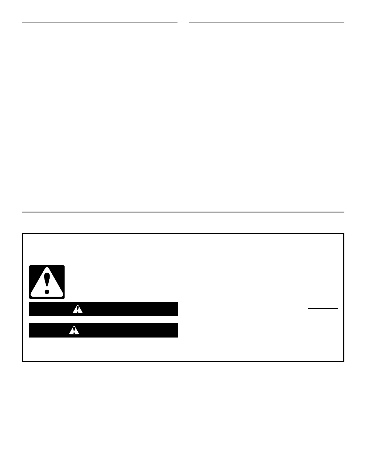
TABLE OF CONTENTS
TABLE DES MATIÈRES
RANGE HOOD SAFETY .................................................................2
INSTALLATION REQUIREMENTS................................................3
Tools and Parts ............................................................................3
Location Requirements................................................................4
Venting Requirements..................................................................4
Electrical Requirements ...............................................................5
INSTALLATION INSTRUCTIONS..................................................6
Venting Options............................................................................6
Prepare Location..........................................................................6
Install Range Hood.......................................................................7
Make Electrical Connection .........................................................8
Install Filters..................................................................................8
Check Operation .......................................................................... 8
RANGE HOOD USE........................................................................9
Range Hood Controls ..................................................................9
RANGE HOOD CARE.....................................................................9
Range Hood Lamps .....................................................................9
Cleaning........................................................................................9
Accessories................................................................................10
ASSISTANCE OR SERVICE.........................................................10
In the U.S.A. ...............................................................................10
In Canada ...................................................................................10
WARRANTY ..................................................................................11
WIRING DIAGRAM .......................................................................12
SÉCURITÉ DE LA HOTTE D’ASPIRATION ................................13
EXIGENCES D'INSTALLATION...................................................15
Outillage et pièces......................................................................15
Exigences d'emplacement.........................................................15
Exigences concernant l'évacuation ...........................................16
Spécifications électriques ..........................................................17
INSTRUCTIONS D’INSTALLATION.............................................18
Options disponibles pour le circuit d'évacuation ......................18
Préparation de l'emplacement...................................................18
Installation de la hotte de cuisinière...........................................19
Raccordement électrique...........................................................20
Installation des filtres..................................................................20
Contrôle du fonctionnement ......................................................20
UTILISATION DE LA HOTTE DE CUISINIÈRE...........................21
Commandes de la hotte de cuisinière .......................................21
ENTRETIEN DE LA HOTTE DE CUISINIÈRE .............................21
Lampes de la hotte de cuisinière...............................................21
Nettoyage ...................................................................................21
Accessoires ................................................................................22
ASSISTANCE OU SERVICE.........................................................22
GARANTIE.....................................................................................23
SCHÉMA DE CÂBLAGE...............................................................24
RANGE HOOD SAFETY
Your safety and the safety of others are very important.
We have provided many important safety messages in this manual and on your appliance. Always read and obey all safety
messages.
This is the safety alert symbol.
This symbol alerts you to potential hazards that can kill or hurt you and others.
All safety messages will follow the safety alert symbol and either the word “DANGER” or “WARNING.”
These words mean:
You can be killed or seriously injured if you don't immediately
DANGER
WARNING
All safety messages will tell you what the potential hazard is, tell you how to reduce the chance of injury, and tell you what can
happen if the instructions are not followed.
follow instructions.
can be killed or seriously injured if you don't
You
instructions.
follow
2
Page 3

IMPORTANT SAFETY INSTRUCTIONS
WARNING: TO REDUCE THE RISK OF FIRE, ELECTRIC
SHOCK, OR INJURY TO PERSONS, OBSERVE THE
FOLLOWING:
■ Use this unit only in the manner intended by the
manufacturer. If you have questions, contact the
manufacturer.
■ Before servicing or cleaning the unit, switch the power off at
the service panel disconnecting means to prevent power
from being switched on accidentally. When the service
disconnecting means cannot be locked, securely fasten a
prominent warning device, such as a tag, to the service
panel.
■ Installation work and electrical wiring must be done by
qualified person(s) in accordance with all applicable codes
& standards, including fire-rated construction.
■ Sufficient air is needed for proper combustion and
exhausting of gases through the flue (chimney) of fuel
burning equipment to prevent backdrafting. Follow the
heating equipment manufacturer's guideline and safety
standards such as those published by the National Fire
Protection Association (NFPA), the American Society for
Heating, Refrigeration and Air Conditioning Engineers
(ASHRAE), and the local code authorities.
■ When cutting or drilling into wall or ceiling; do not damage
electrical wiring and other utilities.
■ Ducted systems must always be vented outdoors.
CAUTION: For general ventilating use only. Do not use
to exhaust hazardous or explosive materials and vapors.
CAUTION: To reduce risk of fire and to properly exhaust
air, be sure to duct air outside - do not vent exhaust air into
spaces within walls ceilings, attics, crawl spaces, or
garages.
WARNING: TO REDUCE THE RISK OF FIRE, USE ONLY
METAL DUCTWORK.
WARNING: TO REDUCE THE RISK OF A RANGE TOP
GREASE FIRE:
■ Never leave the surface units unattended at high settings.
Boilovers cause smoking and greasy spillovers that may
ignite. Heat oils slowly on low or medium settings.
■ Always turn hood ON when cooking at high heat or when
flambeing food (i.e. Crepes Suzette, Cherries Jubilee,
Peppercorn Beef Flambé).
■ Clean ventilating fans frequently. Grease should not be
allowed to accumulate on fan or filter.
■ Use proper pan size. Always use cookware appropriate for
the size of the surface element.
WARNING: TO REDUCE THE RISK OF INJURY TO
PERSONS IN THE EVENT OF A RANGE TOP GREASE
FIRE, OBSERVE THE FOLLOWING:
■ SMOTHER FLAMES with a close fitting lid, cookie sheet, or
other metal tray, then turn off the gas burner or electric
element. BE CAREFUL TO PREVENT BURNS. If the
flames do not go out immediately, EVACUATE AND CALL
THE FIRE DEPARTMENT.
■ NEVER PICK UP A FLAMING PAN - you may be burned.
■ DO NOT USE WATER, including wet dishcloths or towels -
a violent steam explosion will result.
■ Use an extinguisher ONLY if:
– You know you have a class ABC extinguisher, and you
already know how to operate it.
– The fire is small and contained in the area where it
started.
– The fire department is being called.
– You can fight the fire with your back to an exit.
a
Based on "Kitchen Fire Safety Tips" published by NFPA.
■ WARNING: To reduce the risk of fire or electrical shock,
do not use this fan with any solid-state speed control
device.
a
SAVE THESE INSTRUCTIONS
INSTALLATION REQUIREMENTS
Tools and Parts
Gather the required tools and parts before starting installation.
Read and follow the safety instructions provided with any tools
listed here.
Too ls neede d
■ Level
■ Drill
■ 1¹⁄₄" drill bit
■ Pencil
■ Pliers
■ Wire stripper or utility knife
■ Tape measure or ruler
■ Caulking gun and weatherproof caulking compound
■ Saber or keyhole saw
■ Duct tape
■ Flat-blade screwdriver
■ Metal snips
■ Phillips screwdriver
Parts supplied
Check that all parts are included.
■ Literature package
■ Hardware package (4 screws)
Parts needed
UL listed or CSA approved ¹⁄₂" (12.5 mm) strain reliefs (2)
Power supply cable
6" (15.2 cm) round wall or roof cap
6" (15.2 cm) metal vent system
3
Page 4
Location Requirements
(
IMPORTANT: Observe all governing codes and ordinances.
■ It is the installer’s responsibility to comply with installation
clearances specified on the model/serial rating plate. The
model/serial rating plate is located inside the range hood on
the rear wall.
■ Range hood location should be away from strong draft areas,
such as windows, doors and strong heating vents.
■ Cabinet opening dimensions that are shown must be used.
Given dimensions provide minimum clearance. Consult your
cooktop/range manufacturer installation instructions before
making any cutouts.
■ Grounded electrical outlet is required. See “Electrical
Requirements” section.
■ The hood is factory set for vented installations. For
recirculating installations, Recirculation Kit Part Number
4396565, including vent cover and 2 charcoal filters, is
available from your dealer.
■ All openings in ceiling and wall where range hood will be
installed must be sealed.
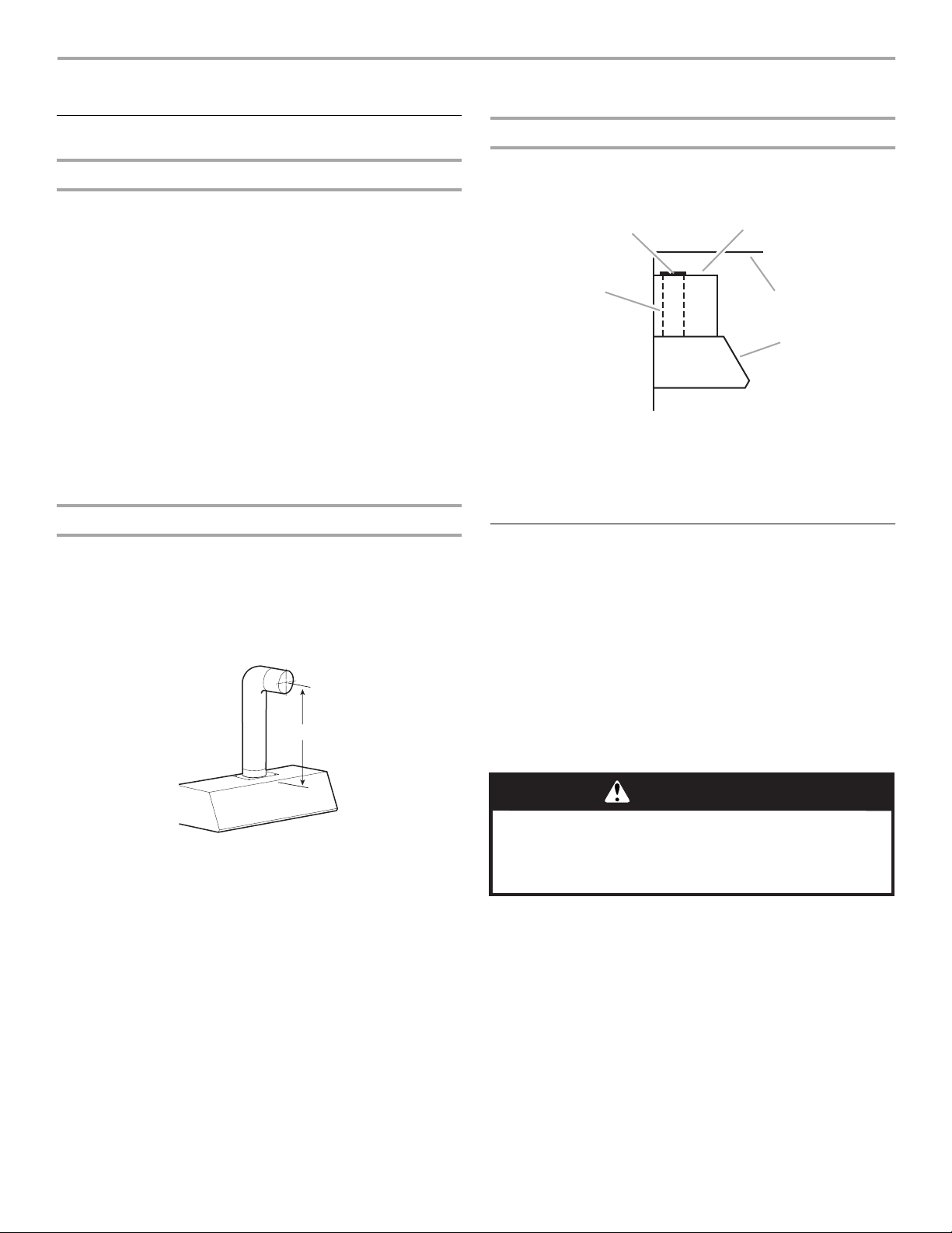
Product Dimensions
Installation Clearances
cabinet opening width
24" (61 cm) min.
30" (76.2 cm)
suggested max.
bottom of hood to
cooking surface
18" (45.7 cm)
min. clearance
upper cabinet
to countertop
30" (76.2 cm) or
36" (91.4 cm) min.
13" (33 cm)
cabinet depth
70
⁵⁄₁₆"
(178.6 cm)
min.
⁵⁄₁₆"
76
(193.8 cm)
max.
to bottom of
cabinet frame
5 ⁷⁄₈" (14.9 cm) diam.
exhaust collar
14 ⁷⁄₈"
(37.8 cm)
10 ⁵⁄₁₆"
26.2 cm)
19 ¹⁄₂"
(49.5 cm)
centerline
of hood
8 ¹⁄₁₆"
(20.5 cm)
29 ⁷⁄₈" (75.9 cm) - 30" (76.2 cm) model
35 ⁷⁄₈" (91.1 cm) - 36" (91.4 cm) model
³⁄₈"
1
(3.5 cm)
Vent and electrical openings and mounting screw locations
mounting screws
5
⁷⁄₈
"
centerline of
exhaust collar
(10.2 cm)
1
³⁄₈
"
(3.5 cm)
(14.9 cm)
diam.
4"
(20.5 cm)
¹⁄₂
13
16
¹⁄₂
locations (4)
centerline
of hood
8
¹⁄₁₆
"
" (34.3 cm) - 30" (76.2 cm) model
" (41.9 cm) - 36" (91.4 cm) model
10
⁹⁄₁₆
(26.8 cm)
"
⁷⁄₈
"
(2.2 mm)
36" (91.4 cm)
base cabinet
height
Venting Requirements
■ Do not terminate the vent system in an attic or other enclosed
area.
■ Do not use a 4" (10.2 cm) laundry-type wall caps.
■ Vent system must terminate to the outside.
■ Use only a 6" (15.2 cm) round metal vent. Rigid metal vent is
recommended. Do not use plastic or metal foil vent.
■ The size of the vent should be uniform.
■ The vent system must have a damper. If roof or wall cap has a
damper, do not use damper supplied with the range hood.
■ Use duct tape to seal all joints in the vent system.
■ Use caulking to seal exterior wall or roof opening around the
cap.
■ Determine which venting method is best for your application.
4
Page 5
For Best Performance:
A
B
A
B
■ Do not install 2 elbows together.
■ Use no more than three 90° elbows.
■ If an elbow is used, install it as far away as possible from the
hood’s vent motor exhaust opening.
■ Make sure there is a minimum of 24" (61 cm) of straight vent
between the elbows if more than one elbow is used.
The length of vent system and number of elbows should be kept
to a minimum to provide efficient performance.
Cold Weather Installations
An additional backdraft damper should be installed to minimize
backward cold air flow and a nonmetallic thermal installed to
minimize conduction of outside temperatures as part of the vent
system. The damper should be on the cold air side of the thermal
break.
Makeup Air
Local building codes may require the use of makeup air systems
when using ventilation systems with greater than specified CFM
of air movement. The specified CFM varies from locale to locale.
Consult your HVAC professional for specific requirements in your
area.
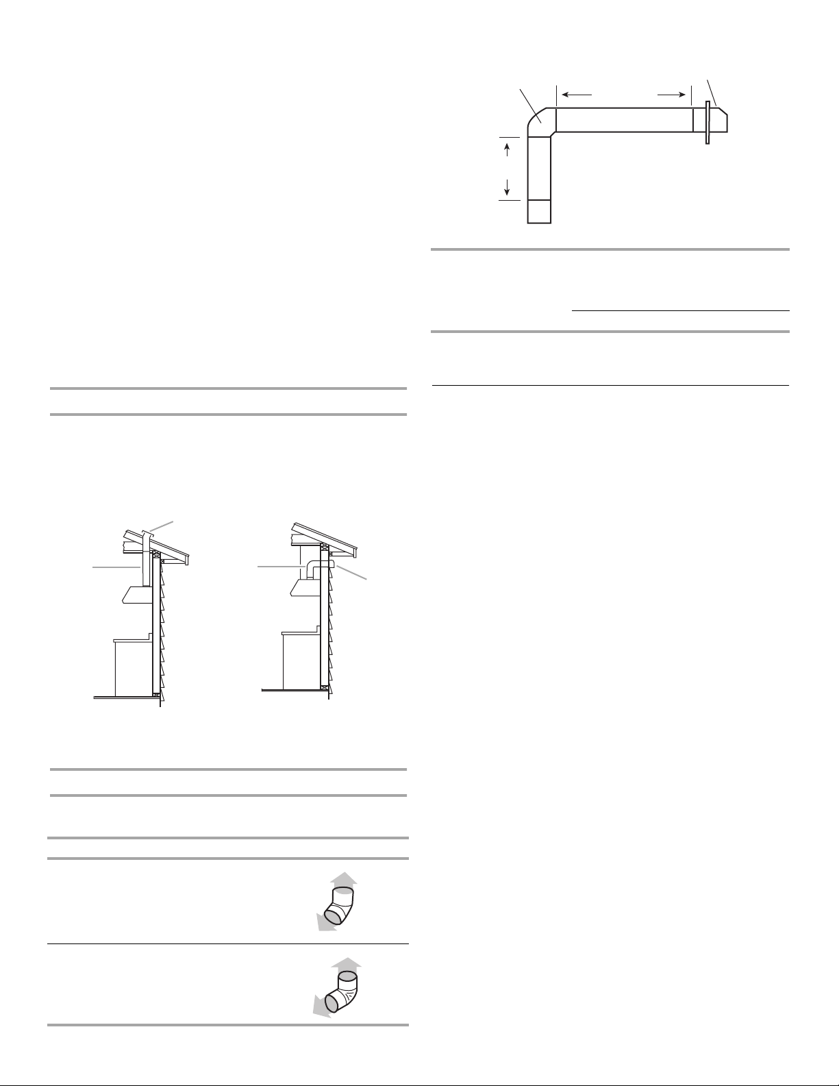
Example vent system
90˚ elbow
6 ft (1.8 m)
2 ft
(0.6 m)
Maximum length = 35 ft (10.7 m)
1- 90° elbow = 5 ft (1.5 m)
8 ft (2.4 m) straight = 8 ft (2.4 m)
1 - wall cap = 0 ft (0 m)
System length = 13 ft (3.9 m)
NOTE: Flexible vent is not recommended. Flexible vent creates
back pressure and air turbulence that greatly reduce
performance.
wall cap
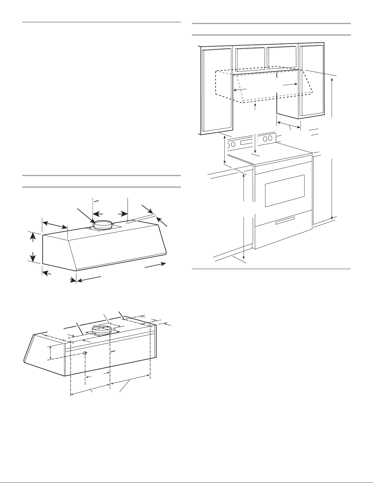
Venting Methods
This range hood is factory set for vented installations. Vent
system can terminate through either the roof or wall. A
6" (15.2 cm) round vent system must be used. The vent system
length should not exceed 35 ft (10.7 m).
Option 1 - Roof Venting Option 2 - Wall Venting
IMPORTANT: Observe all governing codes and ordinances. Save
Installation Instructions for electrical inspector’s use.
It is the customer’s responsibility to contact a qualified electrical
installer, and to assure that the electrical installation is adequate
and in conformance with National Electrical Code, ANSI/NFPA 70
(latest edition), or CSA Standards C22.1-94, Canadian Electrical
Electrical Requirements
Code, Part 1 and C22.2 No. 0-M91 (latest edition) and all local
codes and ordinances.
If codes permit and a separate ground wire is used, it is
recommended that a qualified electrician determine that the
ground path is adequate.
A copy of the above code standards can be obtained from:
National Fire Protection Association
One Batterymarch Park
Quincy, MA 02269
CSA International
8501 East Pleasant Valley Road
Cleveland, OH 44131-5575
■ A 120 Volt, 60 Hz., AC only 15-amp fused, electrical circuit is
A. 6" (15.2 cm) round roof
venting
B. Roof cap
A. 6" (15.2 cm) round wall
venting
B. Wall cap
required.
■ Do not ground to a gas pipe.
■ Check with a qualified electrician if you are not sure range
hood is properly grounded.
Calculating Vent System Length
To calculate the length of the system you need, add the
equivalent feet (meters) for each vent piece used in the system.
Vent piece 6" (15.2 cm) round
45° elbow 2.5 ft (0.8 m)
90° elbow 5.0 ft (1.5 m)
■ Do not have a fuse in the neutral or ground circuit.
■ The range hood must be connected with copper wire only.
■ The range hood should be connected directly to the fused
disconnect (or circuit breaker) box through flexible armored or
nonmetallic sheathed copper cable.
■ Wire sizes (copper wire only) and connections must conform
with the rating of the appliance as specified on the model/
serial rating plate.
■ Wire sizes must conform to the requirements of the National
Electrical Code, ANSI/NFPA 70 (latest edition), or CSA
Standards C22. 1-94, Canadian Electrical Code, Part 1 and
C22.2 No. 0-M91 (latest edition) and all local codes and
ordinances.
■ A ¹⁄₂" (12.7 mm) UL listed or CSA approved strain relief must
be provided at each end of the power supply cable (at the
range hood and at the junction box).
5
Page 6
INSTALLATION INSTRUCTIONS
E
Venting Options
General venting installation
For vented installations:
Make necessary cuts in the wall for vent fittings.
IMPORTANT: Make sure the vent system is installed before
installing range hood.
Rrecirculating installations:
A vent system (not provided) that directs the recirculated air back
into the room either through the soffit or through the cabinet top
is required. Use Recirculation Kit Part Number 4396565. For
ordering information, see “Assistance or Service.”
IMPORTANT: If venting through the cabinet top, do not
terminate the exhaust into dead air space such as an attic or
enclosed soffit.
When venting through the soffit, assemble the vent system you
will use over the exhaust collar, but do not attach the vent system
yet.
NOTE: The vent system can exhaust out the front of the soffit or
be rotated to exhaust out the side or end of the soffit.
Venting through the soffit
1. Assemble the vent system you will use over the exhaust
collar, but do not attach the vent system yet.
NOTE: The vent system can exhaust out the front of the soffit
or be rotated to exhaust out the side or end of the soffit.
2. Measure distance “A” (from top of hood to centerline of
6" [15.2 cm] round vent). Mark the distance “A” on soffit.
A
Venting through cabinet top
1. Mark the location where vent cover will be installed in the
cabinet top and cut a 6" (15.2 cm) round vent opening for the
vent cover.
B
A
A. Vent system
B. Vent cover
C. Cabinet top
IMPORTANT: Do not terminate exhaust into a dead air space
such as an attic or enclosed soffit.
C
D
D. Ceiling or soffit
E. Hood
Prepare Location
■ For vented installations, it is recommended that the vent
system be installed before hood is installed.
■ Do not cut a joist or stud unless absolutely necessary. If a
joist or stud must be cut, then a supporting frame must be
constructed.
■ Before making cutouts, make sure there is proper clearance
within the ceiling or wall for vent fittings.
■ Check that all the installation parts and the box with filters
have been removed from the shipping carton.
Preparation
3. Mark and cut a 6" (15.2 cm) round vent opening.
6
WARNING
Excessive Weight Hazard
Use two or more people to move and install range.
Failure to do so can result in back or other injury.
1. If possible, disconnect power and/or gas supply and move
freestanding or slide-in range from cabinet opening to
provide easier access to rear wall.
Page 7
2. Select a flat surface for assembling the hood. Cover that
)
surface with a protective covering such as a blanket or
cardboard during assembly.
WARNING
8. Cut a 1¹⁄₄" (3.2 cm) hole for power supply cable.
upper cabinet or soffit
mounting surface
8 ¹⁄₁₆
"
(20.5 cm)
Excessive Weight Hazard
Use two or more people to move and install
range hood.
Failure to do so can result in back or other injury.
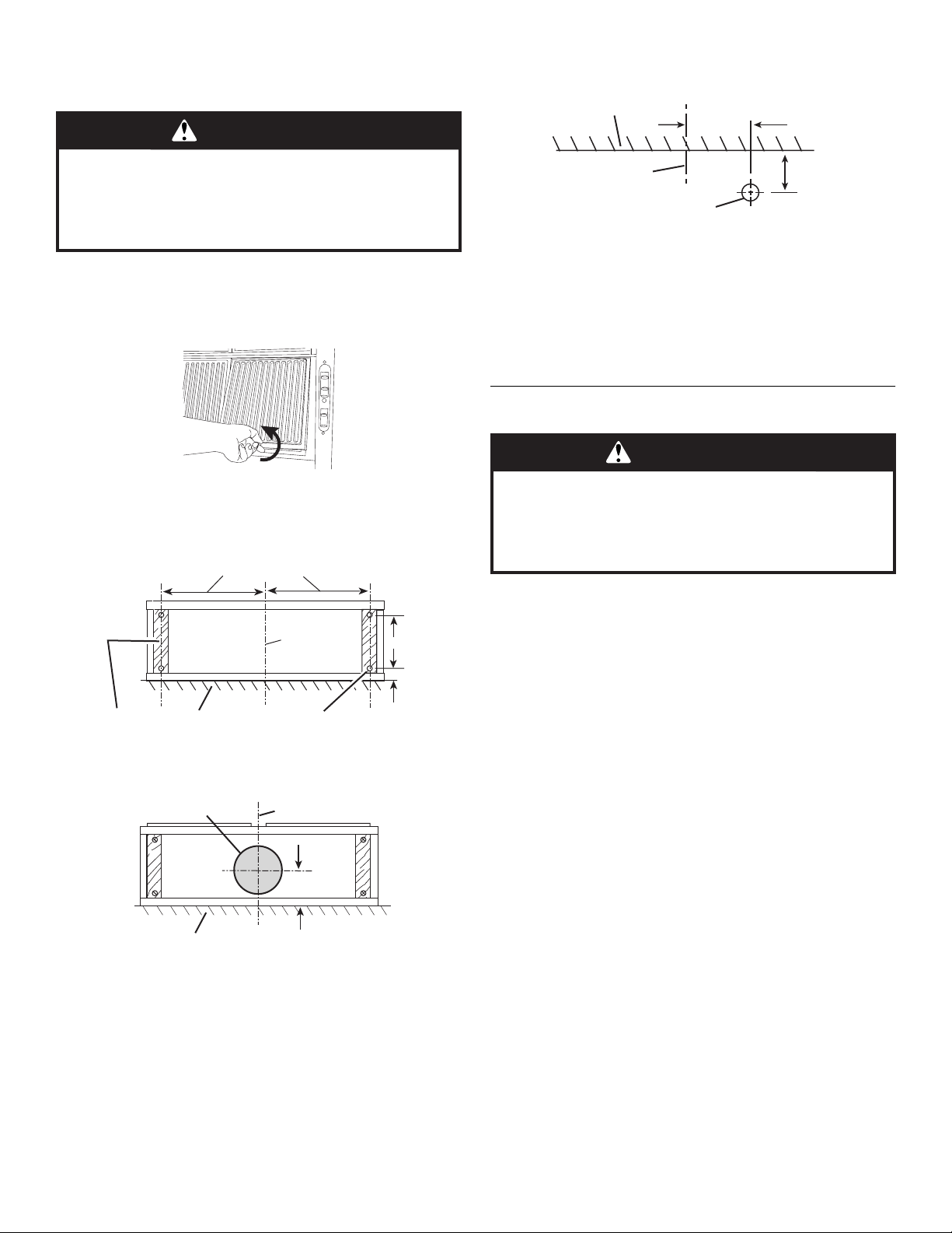
3. Using 2 or more people, slowly lift the range hood onto the
protected surface.
4. Tip range hood on its back to remove the metal filters. Turn
knob to the left (counterclockwise) and lift filters out.
5. Remove hardware package.
6. Add wood filler strips as needed to cabinet bottom. Drill
4 ³⁄₁₆" (4.8 mm) clearance holes for hood mounting screws.
13 ¹⁄₂" (34.3 cm) - 30" (76.2 cm) model
16 ¹⁄₂" (41.9 cm) - 36" (91.4 cm) model
10 ⁹⁄₁₆"
(26.8 cm
⁷⁄₈"
(2.2 cm)
wood filler strips
(recessed cabinet
bottoms only)
wall
centerline
³⁄₁₆" (94.8 mm)
clearance holes
7. Cut a 6¹⁄₂" (16.5 cm) diameter hole in cabinet bottom as
shown.
6 ¹⁄₂" (16.5 cm) diam. hole
wall
centerline
4" (10.2 cm)
centerline
power supply
cable hole in wall
1³⁄₈"
(3.5 cm)
9. Run wire through hole in accordance with the National
Electrical Code or CSA Standards and local codes and
ordinances. There must be enough power supply cable from
the fused disconnect (or circuit breaker) box to make the
connection in the range hood’s electrical box.
10. Use caulking to seal all openings.
IMPORTANT: Do not turn on power until installation is
complete.
Install Range Hood
WARNING
Excessive Weight Hazard
Use two or more people to move and install
range hood.
Failure to do so can result in back or other injury.
1. Remove the terminal box cover (located on back wall of
hood) from the hood. Remove the power supply cable
knockout using a flat-blade screwdriver.
Attach strain relief in power supply cable opening so that
clamping screws are inside of range hood. Tip hood back to
its bottom surface.
2. If roof or wall cap does not have a damper, attach damper to
exhaust opening on top of the range hood using 2 small
screws from hardware package.
3. Place the range hood mounting screws close to the holes in
the cabinet bottom.
4. Lift range hood into place while feeding wiring through strain
relief.
5. Insert the screws through the clearance holes and start them
into the hood. Then, tighten screws securely.
6. Connect vent system, for either vented or recirculating, to
range hood.
7. Seal all joints with duct tape.
8. For recirculating installations, install the vent cover included
in Recirculation Kit Part Number 4396565 in soffit or cabinet
top vent opening.
7
Page 8
Make Electrical Connection
WARNING
Electrical Shock Hazard
Disconnect power before servicing.
Replace all parts and panels before operating.
Failure to do so can result in death or electrical shock.
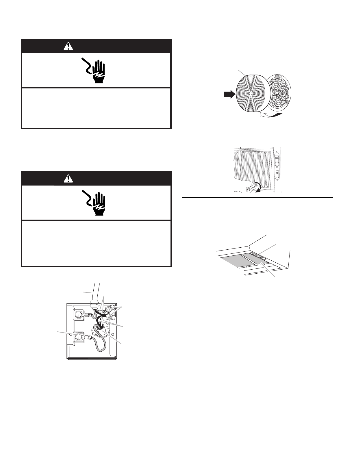
Install Filters
1. For recirculating installations only, install the charcoal filters
included in Recirculation Kit Part Number 4396565. Place the
charcoal filter against the blower cover and rotate to the right
(clockwise) to attach to cover. Repeat with other charcoal
filter.
A
A. Filter
1. Disconnect power at the circuit breaker of fused circuit box.
2. Connect the white wire of the power supply cable with the
white lead in the range hood using a twist-on connector.
3. Connect the black wire of the power supply cable with the
black lead in the range hood using a twist-on connector.
WARNING
Electrical Shock Hazard
Electrically ground blower.
Connect ground wire to green ground screw in
terminal box.
Failure to do so can result in death or electrical shock.
4. Connect the green power supply ground wire to the unused,
green ground screw.
B
C
2. Replace metal filter. Turn knob on metal filter to the right
(clockwise) to attached to range hood.
Check Operation
1. Check operation of the range hood by turning on the power.
2. The range hood controls are located on the right-hand
underside of the range hood.
A
B
A. Controls
B. Filters
A
A. Green ground screw
B. Hood wiring
C. White wires
D. Twist-on connectors
E. Black wires
F. Po w e r s u pp l y ca b le
5. Tighten strain relief screws.
6. Replace the terminal box cover.
8
D
E
F
3. Move the light switch to “1” position. The light should turn on.
4. Move blower switch to “1” position. The blower should
operate.
5. Move the blower speed switch to “1” position for low speed,
“2” position for medium speed or “3” position for high speed.
6. Move blower and light switches to “0” position to turn blower
and light off.
7. If range hood does not operate, check to see whether a
circuit breaker has tripped or a household fuse has blown.
Disconnect power supply and check that the wiring is
correct.
NOTE: To get the most efficient use from your new range hood,
read the “Range Hood Use” section.
Page 9

RANGE HOOD USE
A
The range hood is designed to remove smoke, cooking vapors
and odors from the cooktop area. For best results, start the hood
before cooking and allow it to operate several minutes after the
cooking is complete to clear all smoke and odors from the
kitchen.
The hood controls are located on the right-hand underside of the
range hood.
A
RANGE HOOD CARE
Range Hood Lamps
Replacing a Halogen Lamp
This hood uses four 12-volt, 20-watt halogen lamps.
Turn off the range hood and allow the hallogen lamps to cool.
Replace bulb using a tissue to handle bulb, or wearing cotton
gloves. Do not touch bulb with bare fingers.
To Replace:
1. Disconnect power.
2. Remove 2 screws from the circular metal trim around the
lamp assembly.
3. Pull the trim and lamp assembly down far enough so that the
lamp can be pulled out of the socket clips.
A
CD
B
A. Controls
B. Light switch
C. Blower switch
D. Blower speed switch
Range Hood Controls
Operating the light
1. Move the light switch to the “1” position to turn range hood
light ON.
2. Move the light switch to the “0” position to turn range hood
light OFF.
Operating the blower
1. Move the blower switch to the “1” position to turn the blower
ON. The blower will begin operating at the speed set on the
blower speed switch.
2. Move the blower switch to the “0” position to turn the blower
OFF.
Adjusting the blower
B
A. Remove 2 screws
B. Pull trim with lamp assembly down
4. Insert the new lamp into the socket clips and push the lamp
assembly back up into the hood.
5. Replace the screws.
6. Reconnect the power.
Cleaning
Exterior surfaces:
Do not use steel wool or soap-filled scouring pads. Rub in
direction of the grain line to avoid scratching the surface.
Always wipe dry to avoid water marks.
■ Stainless Steel Cleaner & Polish.
■ Mild liquid detergent and water.
■ Wipe with damp soft cloth or nonabrasive sponge, then rinse
with clean water and wipe dry.
Metal Filters:
For vented installations, use 2 hands to remove filters. Turn the
knob to the left (counterclockwise) to release filter. Repeat with
other filter.
The blower has 3 speed controls. Move the blower speed switch
to “1” position for low speed, “2” position for medium speed or
“3” position for high speed.
Wash metal filters as needed in dishwasher or hot detergent
solution to clean.
9
Page 10

Reinstall the filter by placing the back edge in the channel at rear
of hood. Push filter into place, turn the knob to the right
(clockwise) to attach to range hood. Repeat with other filter.
Recirculating Installation Filters:
For recirculating installations, wash metal filters as needed in
dishwasher or hot detergent solution to clean.
Do not wash charcoal filter packs. Replace with Recirculation Kit
Number 4396565.
Remove the old charcoal filter:
1. Rotate to the left (counterclockwise) and pull away from the
blower cover and discard filter pack. Repeat for other filter.
A
A. Filter
2. Place the charcoal filter against the blower cover and rotate
to the right (clockwise) to attach to cover.
3. Reinstall metal filter by placing back edge in channel at rear
of range hood. Push filter up into place, turn the knob to the
right (clockwise) to attach to range hood. Repeat with other
filter.
Accessories
Optional installation kits are available from your dealer.
Recirculation Kit Part Number 4396565 includes 2 charcoal filter
packs and vent cover.
ASSISTANCE OR SERVICE
Before calling for assistance or service, please check
“Troubleshooting.” It may save you the cost of a service call. If
you still need help, follow the instructions below.
When calling, please know the purchase date and the complete
model and serial number of your appliance. This information will
help us to better respond to your request.
If you need replacement parts
If you need to order replacement parts, we recommend that you
use only factory specified
right and work right because they are made with the same
precision used to build every new KITCHENAID
To locate factory specified parts in your area, call our Customer
eXperience Center telephone number or your nearest designated
service center.
Call the KitchenAid Customer eXperience Center
toll free: 1-800-422-1230.
Our consultants provide assistance with:
■ Features and specifications on our full line of appliances.
■ Installation information.
■ Use and maintenance procedures.
■ Accessory and repair parts sales.
■ Specialized customer assistance (Spanish speaking, hearing
impaired, limited vision, etc.).
■ Referrals to local dealers, repair parts distributors, and
service companies. KitchenAid designated service
technicians are trained to fulfill the product warranty and
provide after-warranty service, anywhere in the United States.
To locate the KitchenAid designated service company in your
area, you can also look in your telephone directory Yellow
Pages.
parts. Factory specified parts will fit
®
appliance.
In the U.S.A.
For further assistance
If you need further assistance, you can write to KitchenAid with
any questions or concerns at:
KitchenAid Brand Home Appliances
Customer eXperience Center
553 Benson Road
Benton Harbor, MI 49022-2692
Please include a daytime phone number in your correspondence.
In Canada
Call the KitchenAid Canada Customer Interaction Centre toll free:
1-800-807-6777.
Our consultants provide assistance with:
■ Features and specifications on our full line of appliances.
■ Use and maintenance procedures.
■ Accessory and repair parts sales.
■ Referrals to local dealers, repair parts distributors, and
service companies. KitchenAid Canada designated service
technicians are trained to fulfill the product warranty and
provide after-warranty service, anywhere in Canada.
For further assistance
If you need further assistance, you can write to KitchenAid
Canada with any questions or concerns at:
Customer Interaction Centre
KitchenAid Canada
1901 Minnesota Court
Mississauga, Ontario L5N 3A7
Please include a daytime phone number in your correspondence.
10
Page 11

KITCHENAID® RANGE HOOD WARRANTY
ONE-YEAR FULL LIMITED WARRANTY
For one year from the date of purchase, when this appliance is operated and maintained according to instructions attached to or
furnished with the product, KitchenAid or KitchenAid Canada will pay for any parts and repair labor costs of your range hood, except
light bulbs and filters, to correct defects in materials or workmanship. Service must be provided by a KitchenAid designated service
company.
KitchenAid or KitchenAid Canada will not pay for:
1. Service calls to correct the installation of your appliance, to instruct you how to use your appliance, to replace house fuses or
correct house wiring, or to replace owner-accessible light bulbs.
2. Consumable parts such as light bulbs and filters.
3. Repairs when your appliance is used in other than normal, single-family household use.
4. Pickup and delivery. Your appliance is designed to be repaired in the home.
5. Damage resulting from accident, alteration, misuse, abuse, fire, flood, improper installation, acts of God or use of products not
approved by KitchenAid or KitchenAid Canada.
6. Repairs to parts or systems resulting from unauthorized modifications made to the appliance.
7. Replacement parts or repair labor costs for units operated outside the United States and Canada.
8. In Canada, travel or transportation expenses for customers who reside in remote areas.
KITCHENAID OR KITCHENAID CANADA SHALL NOT BE LIABLE FOR INCIDENTAL OR CONSEQUENTIAL DAMAGES.
Some states or provinces do not allow the exclusion or limitation of incidental or consequential damages, so this exclusion or limitation
may not apply to you. This warranty gives you specific legal rights and you may also have other rights which may vary from state to
state or province to province.
Outside the 50 United States and Canada, this warranty does not apply. Contact your authorized KitchenAid dealer to
determine if another warranty applies.
If you need service, first see the “Troubleshooting” section of this book. After checking “Troubleshooting,” additional help can be found
by checking the “Assistance or Service” section or by calling the KitchenAid Customer eXperience Center, 1-800-422-1230 (toll-free),
from anywhere in the U.S.A. In Canada, contact your KitchenAid designated service company or call 1-800-807-6777.
4/05
Keep this book and your sales slip together for future
reference. You must provide proof of purchase or installation
date for in-warranty service.
Write down the following information about your appliance to
better help you obtain assistance or service if you ever need it.
You will need to know your complete model number and serial
number. You can find this information on the model and serial
number label/plate, located on your appliance.
Dealer name____________________________________________________
Address ________________________________________________________
Phone number __________________________________________________
Model number __________________________________________________
Serial number __________________________________________________
Purchase date __________________________________________________
11
Page 12

WIRING DIAGRAM
12
CAPACITOR VOLTAGE
Page 13

SÉCURITÉ DE LA HOTTE D’ASPIRATION
Votre sécurité et celle des autres est très importante.
Nous donnons de nombreux messages de sécurité importants dans ce manuel et sur votre appareil ménager. Assurez-vous de
toujours lire tous les messages de sécurité et de vous y conformer.
Voici le symbole d’alerte de sécurité.
Ce symbole d’alerte de sécurité vous signale les dangers potentiels de décès et de blessures graves à vous
et à d’autres.
Tous les messages de sécurité suivront le symbole d’alerte de sécurité et le mot “DANGER” ou
“AVERTISSEMENT”. Ces mots signifient :
Risque possible de décès ou de blessure grave si vous ne
DANGER
AVERTISSEMENT
Tous les messages de sécurité vous diront quel est le danger potentiel et vous disent comment réduire le risque de blessure et
ce qui peut se produire en cas de non-respect des instructions.
suivez pas immédiatement les instructions.
Risque possible de décès ou de blessure grave si vous
ne suivez pas les instructions.
13
Page 14

IMPORTANTES INSTRUCTIONS DE SÉCURITÉ
AVERTISSEMENT : AVERTISSEMENT - POUR
RÉDUIRE LE RISQUE D'INCENDIE, CHOC ÉLECTRIQUE
OU DOMMAGES CORPORELS, RESPECTER LES
INSTRUCTIONS SUIVANTES :
■ Utiliser cet appareil uniquement dans les applications
envisagées par le fabricant. Pour toute question, contacter
le fabricant.
■ Avant d'entreprendre un travail d'entretien ou de nettoyage,
interrompre l'alimentation de la hotte au niveau du tableau
de disjoncteurs, et verrouiller le tableau de disjoncteurs
pour empêcher tout rétablissement accidentel de
l'alimentation du circuit. Lorsqu'il n'est pas possible de
verrouiller le tableau de disjoncteurs, placer sur le tableau
de disjoncteurs une étiquette d'avertissement proéminente
interdisant le rétablissement de l'alimentation.
■ Tout travail d'installation ou câblage électrique doit être
réalisé par une personne qualifiée, dans le respect des
prescriptions de tous les codes et normes applicables, y
compris les codes du bâtiment et de protection contre les
incendies.
■ Une source d'air de débit suffisant est nécessaire pour le
fonctionnement correct de tout appareil à gaz (combustion
et évacuation des gaz à combustion par la cheminée), pour
qu'il n'y ait pas de reflux des gaz de combustion. Respecter
les directives du fabricant de l'équipement de chauffage et
les prescriptions des normes de sécurité - comme celles
publiées par la National Fire Protection Association (NFPA)
et l'American Society for Heating, Refrigeration and Air
Conditioning Engineers (ASHRAE), et les prescriptions des
autorités réglementaires locales.
■ Lors d'opérations de découpage et de perçage dans un mur
ou un plafond, veiller à ne pas endommager les câblages
électriques ou canalisations qui peuvent s'y trouver.
■ Les systèmes d'évacuation doivent toujours décharger l'air
à l'extérieur.
MISE EN GARDE : Cet appareil est conçu uniquement
pour la ventilation générale. Ne pas l'utiliser pour l'extraction
de matières ou vapeurs dangereuses ou explosives.
MISE EN GARDE : Pour minimiser le risque d'incendie
et évacuer adéquatement les gaz, veiller à acheminer l'air
aspiré par un conduit jusqu'à l'extérieur - ne pas décharger
l'air aspiré dans un espace vide du bâtiment comme une
cavité murale, un plafond, un grenier, un vide sanitaire ou
un garage.
AVERTISSEMENT : POUR RÉDUIRE LE RISQUE
D'INCENDIE, UTILISER UNIQUEMENT DES CONDUITS
MÉTALLIQUES.
AVERTISSEMENT : POUR MINIMISER LE RISQUE
D'UN FEU DE GRAISSE SUR LA CUISINIÈRE :
■ Ne jamais laisser un élément de surface fonctionner à
puissance de chauffage maximale sans surveillance. Un
renversement/débordement de matière graisseuse pourrait
provoquer une inflammation et la génération de fumée.
Utiliser une puissance de chauffage moyenne ou basse
pour le chauffage d'huile.
■ Veiller à toujours faire fonctionner le ventilateur de la hotte
lors de la cuisson avec une puissance de chauffage élevée
ou lors de la cuisson d'un mets à flamber (à savoir crêpes
Suzette, cerise jubilée, steak au poivre flambé).
■ Nettoyer fréquemment les ventilateurs d'extraction. Veiller à
ne pas laisser la graisse s'accumuler sur les surfaces du
ventilateur ou des filtres.
■ Utiliser toujours un ustensile de taille appropriée. Utiliser
toujours un ustensile adapté à la taille de l'élément
chauffant.
AVERTISSEMENT : POUR RÉDUIRE LE RISQUE DE
DOMMAGES CORPORELS APRÈS LE DÉCLENCHEMENT
D'UN FEU DE GRAISSE SUR LA CUISINIÈRE, APPLIQUER
LES RECOMMANDATIONS SUIVANTES :
■ Placer sur le récipient un couvercle bien ajusté, une tôle à
biscuits ou un plateau métallique POUR ÉTOUFFER LES
FLAMMES, puis éteindre le brûleur à gaz ou électrique.
VEILLER À ÉVITER LES BRÛLURES. Si les flammes ne
s'éteignent pas immédiatement, ÉVACUER LA PIÈCE ET
APPELER LES POMPIERS.
■ NE JAMAIS PRENDRE EN MAIN UN RÉCIPIENT
ENFLAMMÉ - vous risquez de vous brûler.
■ NE PAS UTILISER D'EAU, ni un torchon humide - ceci
pourrait provoquer une explosion de vapeur brûlante.
■ Utiliser un extincteur SEULEMENT si :
– Il s'agit d'un extincteur de classe ABC, dont on connaît le
fonctionnement.
– Il s'agit d'un petit feu encore limité à l'endroit où il s'est
déclaré.
– Les pompiers ont été contactés.
– Il est possible de garder le dos orienté vers une sortie
pendant l'opération de lutte contre le feu.
a
Recommandations tirées des conseils de sécurité en cas
d'incendie de cuisine publiés par la NFPA.
■ AVERTISSEMENT : Pour réduire le risque d'incendie
ou de choc électrique, ne pas utiliser ce ventilateur avec un
quelconque dispositif de réglage de la vitesse à semiconducteurs.
a
14
CONSERVEZ CES INSTRUCTIONS
Page 15

EXIGENCES D’INSTALLATION
Outillage et pièces
Rassembler les outils et pièces nécessaires avant de commencer
l'installation. Lire et suivre les instructions de sécurité fournies
avec les outils indiqués ici.
Outillage nécessaire
■ Niveau
■ Perceuse
■ Foret de 1¼"
■ Crayon
■ Pince
■ Pince à dénuder ou couteau utilitaire
■ Mètre-ruban ou règle
■ Pistolet à calfeutrage et composé de calfeutrage résistant
aux intempéries
■ Scie sauteuse ou scie à guichet
■ Ruban adhésif pour conduit
■ Tournevis à lame plate
■ Cisaille de ferblantier
■ Tournevis Phillips
Pièces fournies
Vérifier que toutes les pièces sont présentes.
■ Sachet de documents
■ Sachet de pièces de quincaillerie (4 vis)
Pièces nécessaires
Serre-câble de ½" (12,5 mm) (homologation UL ou CSA) (2)
Câble d'alimentation électrique
Bouche de décharge murale ou sur toit de 6" (15,2 cm)
Circuit d'évacuation métallique de dia. 6" (15,2 cm)
■ On doit disposer d'une prise de courant électrique reliée à la
terre. Voir la section “Spécifications électriques”.
■ La hotte a été configurée à l'usine pour une installation avec
décharge à l'extérieur. Pour une installation avec recyclage,
utiliser l’ensemble de recyclage (pièce n° 4396565) qui
contient un cache-conduit et 2 filtres à charbon (disponible
chez les revendeurs).
■ Assurer l'étanchéité au niveau de chaque ouverture
découpée dans le plafond ou le mur pour l'installation de la
hotte de cuisinière.
Dimensions du produit
collerette pour décharge
de dia. 5 ⁷⁄₈" (14,9 cm)
14 ⁷⁄₈"
(37,8 cm)
10 ⁵⁄₁₆"
(26,2 cm)
19 ¹⁄₂"
(49,5 cm)
Emplacement des vis de montage et des ouvertures de
câbles électriques et conduits d'évacuation
axe central
de la collerette
de décharge
4"
(10,2 cm)
axe central
de la hotte
8 ¹⁄₁₆"
(20,5 cm)
29 ⁷⁄₈" (75,9 cm) - modèle de 30" (76,2 cm)
35 ⁷⁄₈" (91,1 cm) - modèle de 36" (91,4 cm)
dia. 5
(14,9 cm)
emplacement des 4
⁷⁄₈"
vis de montage
⁹⁄₁₆"
10
(26,8 cm)
³⁄₈"
1
(3,5 cm)
⁷⁄₈"
(2,2 mm)
Exigences d’emplacement
IMPORTANT : Observer les dispositions de tous les codes et
règlements en vigueur.
■ C'est à l'installateur qu'incombe la responsabilité de
respecter les distances de séparation exigées, spécifiées sur
la plaque signalétique de l'appareil. La plaque signalétique
est située à l'intérieur de la hotte, sur la paroi arrière.
■ Installer la hotte de cuisinière à distance de toute zone
exposée à des courants d'air, comme fenêtres, portes et
bouches de chauffage.
■ Respecter les dimensions indiquées pour la cavité
d'installation entre les placards. Les dimensions indiquées
prennent en compte les valeurs minimales des dégagements
de séparation nécessaires. Avant d'effectuer des
découpages, consulter les instructions d'installation fournies
par le fabricant de la table de cuisson/cuisinière.
1 ³⁄₈"
(3,5 cm)
axe vertical
de la hotte
8
¹⁄₁₆"
(20,5 cm)
13 ¹⁄₂" (34,3 cm) - modèle de 30" (76,2 cm)
16
¹⁄₂" (41,9 cm) - modèle de 36" (91,4 cm)
15
Page 16

Dégagements de séparation à respecter
B
largeur de
l'ouverture du placard
30" (76,2 cm) ou
36" (91,4 cm) min.
Distance suggérée entre
le bas de la hotte et
la table de cuisson :
min. 24" (61 cm) /
max. 30" (76,2 cm)
profondeur
distance
entre le
placard mural
et le plan
de travail
18" (45,7 cm)
min.
Hauteur du placard
de la base :
36" (91,4 cm)
du placard
13" (33 cm)
⁵⁄₁₆"
70
(178,6 cm)
min. et
⁵⁄₁₆"
76
(193,8 cm)
max. jusqu'au
bas du cadre
du placard
Pour obtenir la meilleure performance :
■ Ne pas installer 2 coudes ensemble.
■ Ne pas utiliser plus de trois coudes à 90°.
■ Si un coude est utilisé, on doit le placer le plus loin possible
de l'ouverture de sortie du ventilateur.
■ Veiller à incorporer une section de conduit rectiligne d’au
moins 24" (61 cm) entre deux raccords coudés adjacents.
La longueur du système d'évacuation et le nombre de coudes
doit être réduit au minimum pour fournir la meilleure
performance.
Installations pour régions à climat froid
On devrait installer un clapet antireflux additionnel pour minimiser
le reflux d'air froid, et incorporer un élément non métallique
d'isolation thermique pour minimiser la conduction de chaleur
par l'intermédiaire du conduit d'évacuation, de l'intérieur de la
maison à l'extérieur. Le clapet anti-reflux doit être placé du côté
air froid par rapport à l'élément d'isolation thermique.
Air d’appoint
Le code du bâtiment local peut exiger l'emploi d'un système
d'appoint d'air lors de l'emploi d'un ventilateur d'extraction dont
la capacité d'aspiration est supérieure à un débit (pieds cubes
par minute) spécifié. Le débit spécifié, pieds cubes par minute,
est variable d'une juridiction à une autre. Consulter un
professionnel des installations de chauffage ventilation/
climatisation au sujet des exigences spécifiques applicables
dans la juridiction locale.
Méthodes d'évacuation
Exigences concernant l'évacuation
■ Ne pas terminer le conduit d'évacuation dans un grenier ou
dans un autre espace fermé.
■ Ne pas utiliser une bouche de décharge murale de
4" (10,2 cm) normalement utilisée pour un équipement de
buanderie.
■ Le système doit décharger l'air à l'extérieur.
■ Utiliser uniquement du conduit métallique de 6" (15,2 cm). Un
conduit en métal rigide est recommandé. Ne pas utiliser un
conduit de plastique ou en métal mince.
■ La taille du conduit doit être uniforme.
■ Le système d'évacuation doit comporter un clapet. Si la
bouche de décharge murale ou par le toit comporte un
clapet, ne pas utiliser le clapet fourni avec la hotte de
cuisinière.
■ Au niveau de chaque jointure du conduit de décharge,
assurer l'étanchéité avec du ruban adhésif pour conduit.
■ Autour de la bouche de décharge à l'extérieur, assurer
l'étanchéité avec un produit de calfeutrage.
■ Déterminer quelle méthode d'évacuation est la plus
appropriée.
La hotte de cuisinière a été configurée à l'usine pour l'installation
avec décharge à l'extérieur. La décharge de l'air aspiré peut être
effectuée à travers le mur ou le toit. On doit utiliser un circuit
d'évacuation de dia. 6" (15,2 cm). La longueur effective du circuit
d'évacuation ne doit pas dépasser 35 pi (10,7 m).
Option 1 - Décharge à
travers le toit
Option 2 - Décharge à
travers le mur
B
A
A. Conduit de dia. 6" (15,2 cm) -
sortie à travers le toit
B. Bouche de décharge sur le toit
A
A. Conduit de dia. 6" (15,2 cm) -
sortie à travers le mur
B. Bouche de décharge murale
16
Page 17

Calcul de la longueur effective du circuit d'évacuation
coude à 90˚
2 pi
(0,6 m)
6 pi (1,8 m)
bouche de décharge murale
Pour calculer la longueur effective du circuit d'évacuation
nécessaire, additionner les longueurs équivalentes (pieds/mètres)
de tous les composants utilisés dans le système.
Composant Conduit et raccords dia. 6" (15,2 cm)
coude à 45° 2,5 pi (0,8 m)
coude à 90° 5 pi (1,5 m)
Exemple de système de décharge
Longueur maximum = 35 pi (10,7 m)
1 - coude à 90° = 5 pi (1,5 m)
section droite de
8 pi (2,4 m)
1 - bouche de
décharge murale
Longueur totale = 13 pi (3,9 m)
REMARQUE : On déconseille l'emploi d'un conduit flexible. Un
conduit flexible peut susciter une rétro-pression et des
turbulences de l'air, ce qui réduit considérablement la
performance.
= 8 pi (2,4 m)
= 0 pi (0 m)
Spécifications électriques
IMPORTANT : Observer les dispositions de tous les codes et
règlements en vigueur. Conserver les instructions d'installation
pour consultation par l'inspecteur des installations électriques.
C'est au client qu'incombe la responsabilité de contacter un
électricien qualifié et de veiller à ce que l'installation électrique
soit adéquate et réalisée en conformité avec les prescriptions de
la plus récente édition de la norme National Electrical Code,
ANSI/NFPA 70, ou de la norme CSA C22.1-94, Code canadien de
l'électricité, partie 1 et C22.2 N° 0-M91, et de tous les codes et
règlements locaux en vigueur.
Si les codes le permettent et si on utilise un conducteur distinct
de liaison à la terre, il est recommandé qu'un électricien qualifié
vérifie la qualité de la liaison à la terre.
Pour obtenir un exemplaire de la norme des codes ci-dessus,
contacter :
National Fire Protection Association
One Batterymarch Park, Quincy, MA 02269
CSA International
8501 East Pleasant Valley Road
Cleveland, OH 44131-5575
■ L'appareil doit être alimenté par un circuit de 120 V, 60 Hz,
CA seulement, 15 ampères, protégé par fusible.
■ Ne pas utiliser une tuyauterie de gaz pour le raccordement à
la terre.
■ En cas de doute quant à la qualité de la liaison à la terre de la
hotte de la cuisinière, consulter un électricien qualifié.
■ Ne pas installer un fusible dans le conducteur neutre ou le
conducteur de liaison à la terre.
■ La hotte doit être raccordée au réseau électrique uniquement
avec des conducteurs de cuivre.
■ La hotte doit être raccordée directement au coupe-circuit
avec fusible ou au disjoncteur par l'intermédiaire de câble à
conducteurs de cuivre, à blindage métallique flexible ou à
gaine non-métallique.
■ Le calibre des conducteurs (cuivre seulement) et les
connexions doivent être compatibles avec la demande de
courant de l'appareil spécifiée sur la plaque signalétique.
■ Le calibre des conducteurs doit satisfaire les exigences de la
plus récente édition de la norme National Electrical Code,
ANSI/NFPA 70, ou de la norme CSA C22.1-94, Code
canadien de l'électricité, partie 1 et C22.2 N° 0-M91 et de
tous les codes et règlements en vigueur.
■ Un serre-câble de ½" (12,7 mm) (homologation UL ou CSA)
doit être installé à chaque extrémité du câble d'alimentation
(sur la hotte et sur le boîtier de distribution).
17
Page 18

INSTRUCTIONS D’INSTALLATION
E
Options disponibles pour le circuit
d'évacuation
Instructions générales
Installation avec décharge à l'extérieur :
Exécuter les découpages nécessaires dans le mur pour le
passage des conduits.
IMPORTANT : Veiller à installer le circuit d'évacuation avant
d'entreprendre l'installation de la hotte.
Installation avec recyclage :
Un circuit d'évacuation (non fourni) qui décharge l'air aspiré dans
la pièce, à travers le soffite ou à travers le sommet du placard, est
nécessaire. Utiliser l'ensemble de recyclage numéro 4396565.
Pour l'information de commande, voir “Assistance ou service”.
IMPORTANT : Dans le cas de la décharge de l'air à travers le
sommet du placard, veiller à ne pas terminer le conduit de
décharge dans un espace fermé comme un grenier ou une cavité
fermée sous le soffite.
Dans le cas de la décharge de l'air à travers le soffite, placer le
circuit d'évacuation à utiliser sur le raccord de sortie, mais sans
déjà le fixer.
REMARQUE : On peut placer le conduit d'évacuation de telle
manière qu'il décharge l'air aspiré par l'avant du soffite, ou par
l'une des extrémités latérales du soffite.
Décharge à travers le soffite
1. Placer le circuit d'évacuation à utiliser sur le raccord de
sortie, mais sans déjà le fixer.
REMARQUE : On peut placer le conduit d'évacuation de telle
manière qu'il décharge l'air aspiré par l'avant du soffite, ou
par l'une des extrémités latérales du soffite.
2. Relever la dimension “A” (entre le sommet de la hotte et l'axe
central du conduit de diamètre 6" [15,2 cm]). Reporter la
distance “A” sur le soffite.
Décharge à travers le sommet du placard
1. Marquer l'emplacement où la grille de sortie sera installée au
sommet du placard; et découper une ouverture de dia.
6" (15,2 cm) pour la grille de sortie.
B
A
A. Circuit d'évacuation
B. Emplacement de la
grille de sortie
IMPORTANT : Ne pas terminer le conduit de décharge dans
un espace fermé comme un grenier ou une cavité fermée
sous le soffite.
C
D
C. Sommet du placard
D. Plafond ou soffite
E. Hotte
Préparation de l'emplacement
■ Installations avec décharge à l'extérieur : on recommande
d'installer le circuit d'évacuation avant d'entreprendre
l'installation de la hotte.
■ On ne doit couper un poteau de colombage ou une solive
que si c'est absolument nécessaire. S'il est nécessaire de
couper un poteau ou une solive, on devra construire une
structure de support appropriée.
■ Avant d'exécuter les découpages, vérifier la disponibilité d'un
espace de passage suffisant dans le plafond ou le mur pour
le conduit d'évacuation.
■ Vérifier que toutes les pièces et la boîte contenant les filtres
ont été retirées de l'emballage.
A
3. Relever les dimensions appropriées et découper une
ouverture de dia. 6" (15,2 cm).
18
Préparation
AVERTISSEMENT
Risque du poids excessif
Utiliser deux ou plus de personnes pour déplacer et
installer la cuisinière.
Le non-respect de cette instruction peut causer
une blessure au dos ou d'autre blessure.
1. Si possible, déconnecter la cuisinière des circuits d'électricité
et/ou de gaz et déplacer la cuisinière autonome ou encastrée
hors de son espace d'installation entre les placards pour
faciliter l'accès au mur arrière.
Page 19

2. Sélectionner une surface plane pour l'assemblage de la
)
hotte. Lors de l'assemblage, recouvrir cette surface avec un
matériau de protection - couverture ou feuille de carton.
AVERTISSEMENT
8. Percer un trou de 1¹⁄₄" (3,2 cm) pour le passage du câble
d'alimentation.
surface de montage
(placard mural ou soffite)
8¹⁄₁₆"
(20,5 cm)
Risque du poids excessif
Utiliser deux ou plus de personnes pour déplacer et
installer la hotte de la cuisinière.
Le non-respect de cette instruction peut causer
une blessure au dos ou d'autre blessure.
3. Faire intervenir 2 personnes ou plus pour soulever la hotte
pour la placer sur la surface protégée.
4. Placer la hotte sur sa face arrière pour enlever les filtres
métalliques. Faire tourner le bouton dans le sens antihoraire
et soulever pour enlever les filtres.
5. Retirer le paquet de pièces de quincaillerie.
6. Ajouter des tringles d'appui en bois selon le besoin, sur le
fond du placard. Percer des avant-trous de 4 ³⁄₁₆" (4,8 mm)
pour les vis de montage de la hotte.
13 ¹⁄₂" (34,3 cm) - modèle de 30" (76,2 cm)
16 ¹⁄₂" (41,9 cm) - modèle de 36" (91,4 cm)
axe central
trou de passage
du câble d'alimentation
à travers le mur
1³⁄₈"
(3,5 cm)
9. Placer le câble d'alimentation à travers le trou conformément
aux prescriptions des normes et codes en vigueur - National
Electrical Code ou normes CSA, codes et règlements locaux.
Il faut que la longueur du câble d'alimentation soit suffisante
entre le câble de distribution et la hotte pour qu'il soit facile
de réaliser les raccordements dans le boîtier de connexion de
la hotte.
10. Utiliser un calfeutrant pour assurer l'étanchéité au niveau de
chaque ouverture découpée.
IMPORTANT : Ne pas mettre le système sous tension avant
d'avoir complètement terminé l'installation.
Installation de la hotte de cuisinière
AVERTISSEMENT
Risque du poids excessif
Utiliser deux ou plus de personnes pour déplacer et
installer la hotte de la cuisinière.
Le non-respect de cette instruction peut causer
une blessure au dos ou d'autre blessure.
10 ⁹⁄₁₆"
(26,8 cm
⁷⁄₈"
(2,2 cm)
cales de bois
(seulement pour un
placard mural avec
fond en retrait)
mur
axe central
trous de
³⁄₁₆" (94,8 mm)
7. Percer un trou de diamètre de 6¹⁄₂" (16,5 cm) dans le fond du
placard - voir l'illustration.
trou dia. 6 ¹⁄₂" (16,5 cm)
mur
axe central
4" (10,2 cm)
1. Ôter le couvercle du boîtier de connexion (paroi arrière de la
hotte). Avec un tournevis à lame plate, enlever l'opercule
arrachable du trou de passage du câble.
Installer le serre-câble sur le trou; veiller à ce qu'il soit facile
de visser les vis de bridage à l'intérieur de la hotte. Placer la
hotte en appui sur sa surface inférieure.
2. Si la bouche de décharge murale ou sur toit ne comporte pas
de clapet anti-reflux, installer le clapet anti-reflux sur
l'ouverture de sortie au sommet de la hotte - utiliser 2 petites
vis du sachet de pièces de quincaillerie.
3. Placer les vis de montage de la hotte à proximité des trous
percés dans le fond du placard.
4. Soulever la hotte jusqu'à sa position de service tout en
enfilant le câble à travers le serre-câble.
5. Insérer les vis dans les trous de passage et commencer à
visser les vis dans la hotte. Ensuite, bien serrer les vis.
6. Connecter le circuit d'évacuation - pour décharge à
l'extérieur ou pour recyclage - sur la hotte.
7. Assurer l'étanchéité des jointures avec du ruban adhésif pour
conduits.
8. Pour une installation avec recyclage, installer la grille de
sortie fournie avec l'ensemble de recyclage numéro 4396565
sur l'ouverture de décharge du soffite ou au sommet du
placard.
19
Page 20

Raccordement électrique
5. Serrer les vis du serre-câble.
6. Réinstaller le couvercle du boîtier de connexion.
AVERTISSEMENT
Risque de choc électrique
Déconnecter la source de courant électrique avant
l'entretien.
Replacer pièces et panneaux avant de faire la remise
en marche.
Le non-respect de ces instructions peut causer
un décès ou un choc électrique.
1. Déconnecter la source de courant électrique au niveau du
disjoncteur ou du circuit à fusibles.
2. Dans le boîtier de connexion de la hotte, connecter ensemble
le conducteur blanc du câble d'alimentation et le conducteur
blanc de la hotte, avec un connecteur de fil.
3. Dans le boîtier de connexion de la hotte, connecter ensemble
le conducteur noir du câble d'alimentation et le conducteur
noir de la hotte, avec un connecteur de fil.
Installation des filtres
1. Seulement pour l'installation avec recyclage : installer les
filtres à charbon fournis avec l'ensemble de recyclage
numéro 4396565. Placer le filtre à charbon contre la grille du
ventilateur et effectuer une rotation dans le sens horaire pour
fixer le filtre sur la grille. Répéter pour l'autre filtre à charbon.
A
A. Filtre
2. Réinstaller le filtre métallique. Faire tourner le bouton du filtre
métallique dans le sens horaire pour le fixer sur la hotte.
AVERTISSEMENT
Risque de choc électrique
Relier le ventilateur à la terre.
Brancher le fil relié à la terre à la vis verte reliée la terre
dans la boîte de la borne.
Le non-respect de cette instruction peut causer
un décès ou un choc électrique.
4. Connecter le conducteur vert de liaison à la terre à la vis verte
de liaison à la terre inutilisée.
B
A
A. Vis verte de liaison à la terre
B. Câble de la hotte
C. Conducteurs blancs
C
D
E
F
D. Connecteur de fil
E. Conducteurs noirs
F. C âble d'alimentation électrique
Contrôle du fonctionnement
1. Mettre l'appareil sous tension pour vérifier le bon
fonctionnement de la hotte.
2. Les commandes sont situées sous la hotte, du côté droit.
A
B
A. Commandes
B. Filtres
3. Pousser le commutateur d'éclairage à la position “1”. La
lampe devrait s'allumer.
4. Pousser le commutateur du ventilateur à la position “1”. Le
ventilateur devrait fonctionner.
5. Placer le sélecteur de vitesse du ventilateur à la position “1”
pour la basse vitesse, à la position “2” pour la vitesse
moyenne ou à la position “3” pour la haute vitesse.
6. Pour commander l'arrêt du ventilateur et l'extinction des
lampes, placer les commutateurs à la position “0”.
7. Si la hotte ne fonctionne pas, déterminer si le circuit est
correctement alimenté (disjoncteur ouvert ou fusible grillé?).
Interrompre l'alimentation électrique du circuit et vérifier que
le câblage est correct.
REMARQUE : Pour pouvoir tirer le plus grand parti de la hotte de
cuisinière, lire la section “Utilisation de la hotte de cuisinière”.
20
Page 21

UTILISATION DE LA HOTTE DE CUISINIÈRE
A
A
B
La hotte de cuisinière est conçue pour extraire fumée, vapeurs de
cuisson et odeurs au-dessus de la table de cuisson. Pour obtenir
les meilleurs résultats, mettre le ventilateur de la hotte en marche
avant d'entreprendre une cuisson, et laisser le ventilateur
fonctionner pendant plusieurs minutes après l'achèvement d'une
cuisson pour pouvoir évacuer de la cuisine toute trace d'odeur
de cuisson, vapeur ou fumée.
Les commandes sont situées sous la hotte, du côté droit.
A
CD
B
A. Commandes
B. Commutateur d'éclairage
C. Commutateur du ventilateur
D. Sélecteur de vitesse du ventilateur
Commandes de la hotte de cuisinière
Commande du luminaire
1. Placer le commutateur d'éclairage à la position “1” pour
commander l'allumage.
2. Placer le commutateur d'éclairage à la position “0” pour
commander l'extinction.
Utilisation du ventilateur
1. Placer le commutateur du ventilateur à la position “1” pour
commander la mise en marche du ventilateur. Le ventilateur
commencera à fonctionner à la vitesse déjà sélectionnée par
le sélecteur de vitesse.
2. Placer le commutateur du ventilateur à la position “0” pour
commander l'arrêt du ventilateur.
Réglage du ventilateur
Le sélecteur de vitesse du ventilateur comporte 3 positions.
Placer le bouton à la position “1” pour la basse vitesse, à la
position “2” pour la vitesse moyenne ou à la position “3” pour la
haute vitesse.
ENTRETIEN DE LA HOTTE DE CUISINIÈRE
Lampes de la hotte de cuisinière
Remplacement d'une lampe à halogène.
L'éclairage sous la hotte est assuré par des lampes à halogène
(12 volts 20 watts).
Interrompre l'alimentation électrique de la hotte et laisser les
lampes refroidir.
Ne pas toucher une lampe à halogène à mains nues. Remplacer
la lampe en utilisant un chiffon pour la manipulation ou en portant
des gants en coton. Pour le remplacement :
1. Déconnecter la source de courant électrique.
2. Ôter les 2 vis de fixation de la garniture métallique circulaire
de la lampe.
3. Tirer vers le bas l'ensemble garniture/lampe suffisamment
pour qu'il soit possible de dégager la lampe de ses agrafes
de retenue.
A. Retirer 2 vis
B. Tirer vers le bas l'ensemble garniture/lampe
4. Insérer la lampe neuve dans les agrafes de la douille;
repousser l'ensemble garniture/lampe vers le haut dans
hotte.
5. Réinstaller les 2 vis.
6. Reconnecter la source de courant électrique.
Nettoyage
Surfaces externes :
Ne pas utiliser de tampon de laine d'acier ni de tampon de
récurage savonneux. Frotter dans la direction des lignes du grain
pour ne pas détériorer la surface.
Toujo urs s écher par essuyage pour éviter de laisser des marques
d'eau.
■ Nettoyant et poli pour acier inoxydable.
■ Détergent liquide doux et eau.
■ Frotter avec un chiffon doux humidifié ou une éponge non
abrasive, puis rincer avec de l'eau propre et sécher par
essuyage.
21
Page 22

Filtres métalliques :
Pour une installation avec décharge à l'extérieur, employer les
2 mains pour enlever les filtres. Faire tourner le bouton dans le
sens antihoraire pour libérer le filtre. Répéter pour l'autre filtre.
Laver le filtre métallique selon le besoin au lave-vaisselle ou avec
une solution de détergent chaude.
Réinstaller le filtre en plaçant le bord arrière dans la rainure à
l'arrière de la hotte. Pousser le filtre pour la mise en place; faire
tourner le bouton dans le sens horaire pour la fixation sur la
hotte. Répéter pour l'autre filtre.
Dépose des vieux filtres à charbon :
1. Faire pivoter le filtre dans le sens antihoraire et écarter pour le
séparer de la grille du ventilateur; jeter les vieux filtres.
Répéter pour l'autre filtre.
A
A. Filtre
2. Placer le filtre à charbon contre la grille du ventilateur; faire
pivoter dans le sens horaire pour fixer le filtre sur la grille.
3. Réinstaller le filtre métallique; insérer le bord arrière dans la
rainure à l'arrière de la hotte. Pousser le filtre vers le haut pour
la mise en place; faire tourner le bouton dans le sens horaire
pour la fixation sur la hotte. Répéter pour l'autre filtre.
Accessoires
Des ensembles d’installation facultatifs sont disponibles chez le
revendeur.
Ensemble de recyclage pièce numéro 4396565 comprenant
2 filtres à charbon et le cache-conduit.
Filtres pour installation avec recyclage :
Pour les installations avec recyclage, laver les filtres métalliques
selon le besoin au lave-vaisselle ou avec une solution de
détergent chaude.
Ne pas laver les filtres à charbon; remplacer avec le filtre de
l'ensemble de recyclage numéro 4396565.
ASSISTANCE OU SERVICE
Avant de faire un appel pour assistance ou service, consulter la
section “Dépannage”. Ce guide peut vous faire économiser le
coût d’une visite de service. Si vous avez encore besoin d’aide,
suivre les instructions ci-dessous.
Lors d’un appel, veuillez connaître la date d’achat, le numéro de
modèle et le numéro de série au complet de l’appareil. Ces
renseignements nous aideront à mieux répondre à votre
demande.
Si vous avez besoin de pièces de rechange
Si vous avez besoin de commander des pièces de rechange,
nous vous recommandons d’employer uniquement des pièces
spécifiées par l'usine. Les pièces spécifiées par l'usine
conviendront et fonctionneront bien parce qu’elles sont
fabriquées avec la même précision que celles utilisées dans la
fabrication de chaque nouvel appareil KITCHENAID
Pour localiser des pièces spécifiées par l'usine dans votre région,
contactez-nous ou appelez le centre de service désigné de
KitchenAid le plus proche.
Veuillez appeler sans frais le Centre d’interaction avec la clientèle
de KitchenAid Canada au : 1-800-807-6777.
®
.
Nos consultants vous renseigneront sur les sujets suivants :
■ Caractéristiques et spécifications sur toute notre gamme
d’appareils électroménagers.
■ Utilisation et consignes d’entretien.
■ Ventes d’accessoires et pièces de rechange.
■ Références aux marchands locaux, aux distributeurs de
pièces de rechange et aux compagnies de service. Les
techniciens de service désignés par KitchenAid Canada sont
formés pour remplir la garantie des produits et fournir un
service après la garantie, partout au Canada.
Pour plus d’assistance
Si vous avez besoin de plus d’assistance, vous pouvez
soumettre par écrit toute question ou préoccupation à
KitchenAid Canada à l’adresse suivante :
Centre d’interaction avec la clientèle
KitchenAid Canada
1901 Minnesota Court
Mississauga, Ontario L5N 3A7
Veuillez inclure dans votre correspondance un numéro de
téléphone où l’on peut vous joindre dans la journée.
22
Page 23

GARANTIE DE LA HOTTE DE CUISINIÈRE KITCHENAID
GARANTIE COMPLÈTE DE UN AN
Pendant un an à compter de la date d'achat, lorsque cet appareil est utilisé et entretenu conformément aux instructions jointes à ou
fournies avec le produit, KitchenAid Canada paiera pour les pièces et les frais de main-d'œuvre liés à la réparation de votre hotte de
cuisinière (sauf ampoules et filtres) pour corriger les vices de matériaux ou de fabrication. Le service doit être fourni par une compagnie
de service désignée par KitchenAid.
KitchenAid Canada ne paiera pas :
1. Les visites de service pour rectifier l'installation de l'appareil ménager, montrer à l'utilisateur comment utiliser l'appareil, remplacer
des fusibles ou rectifier le câblage du domicile ou remplacer des ampoules électriques accessibles par le propriétaire.
2. Les pièces consomptibles comme ampoules et filtres.
3. Les réparations lorsque l'appareil ménager est utilisé à des fins autres que l'usage unifamilial normal.
4. Le ramassage et la livraison. L'appareil ménager est conçu pour être réparé à domicile.
5. Les dommages causés par : accident, modification, mésusage, abus, incendie, inondation, mauvaise installation, actes de Dieu ou
l'utilisation de produits non approuvés par KitchenAid Canada.
6. Les réparations aux pièces ou systèmes résultant d'une modification non autorisée faite à l'appareil.
7. Le coût des pièces de rechange et de la main-d'œuvre pour les appareils utilisés hors du Canada.
8. Les frais de voyage ou de transport pour les clients qui habitent dans des régions éloignées.
KITCHENAID CANADA N'ASSUME AUCUNE RESPONSABILITÉ POUR LES DOMMAGES FORTUITS OU INDIRECTS.
Certaines provinces ne permettent pas l’exclusion ou la limitation des dommages fortuits ou indirects de sorte que cette exclusion ou
limitation peut ne pas être applicable dans votre cas. Cette garantie vous confère des droits juridiques spécifiques et vous pouvez
également jouir d'autres droits qui peuvent varier d'une province à une autre.
À l'extérieur du Canada, cette garantie ne s'applique pas. Contacter votre marchand KitchenAid autorisé pour déterminer si
une autre garantie s'applique.
Si vous avez besoin de service, voir d’abord la section “Dépannage” de ce manuel. Après avoir vérifié la section “Dépannage”, une aide
additionnelle peut être trouvée en vérifiant la section “Assistance ou service” ou en téléphonant
sans frais au 1-800-807-6777.
®
4/05
Conservez ce manuel et votre reçu de vente ensemble pour
référence ultérieure. Pour le service sous garantie, vous
devez présenter un document prouvant la date d'achat ou
d'installation.
Inscrivez les renseignements suivants au sujet de votre appareil
ménager pour mieux vous aider à obtenir assistance ou service
en cas de besoin. Vous devrez connaître le numéro de modèle et
le numéro de série au complet. Cette information se trouve sur la
plaque signalétique indiquant le numéro de série et le numéro de
modèle, située sur votre appareil.
Nom du marchand ______________________________________________
Adresse ________________________________________________________
Numéro de téléphone ___________________________________________
Numéro de modèle______________________________________________
Numéro de série ________________________________________________
Date d’achat____________________________________________________
23
Page 24

SCHÉMA DE CÂBLAGE
COMMUTATEURS À GLISSIÈRE
ÉCLAIRAGE MOTEUR VITESSE
BOÎTIER DE
CONNEXION
N
T
BL
N
MAR
T
BL
VI
BL
MAR
GRIS
N
BL
GRIS
TOROÏDAL
TRANSFORMATEUR
TÉMOINS (DIRECTION)
427500564/9760927A
© 2005. All rights reserved.
Tous droits réservés.
N
BL
JA
MAR
GRIS
CONDENSATEUR TENSION
T
GROUPE MOTEUR
® Registered Trademark/TM Trademark of KitchenAid, U.S.A., KitchenAid Canada licensee in Canada
® Marque déposée/TM Marque de commerce de KitchenAid, U.S.A., Emploi licencié par KitchenAid Canada au Canada
Printed in Italy
Imprimé en Italie
4/05
 Loading...