

KitchenAid Range Installation Manual
INSTALLER: LEA VE THESE INSTRUCTIONS WITH THE APPLIANCE
ELECTRIC INSTALLATION MANUAL
30" WIDE FREE-STANDING, SLIDE-IN
AND DROP-IN
PLEASE KEEP THIS MANUAL FOR FUTURE REFERENCE
THE MANUAL IS INTENDED TO ASSIST IN THE INITIAL INSTALLATION AND ADJUSTMENTS OF THE RANGE.
i
iii:iS_PE_IALWARNING
• : . . i_ .:
:_UALIFIEDPERSONNEL-SHOULD_.INSTALL OR SE,RVICETHIS_RANGE.
READ ffSAFETYINSTRUCTIONS",IN USE&.CAREBOOK BEFOREUSINGRANGE.
• X
CLEARANCE DIMENSIONS
All free-standing ranges can be installed with the back against (0 inches) a vertical combustible wall, and
the sides below the cooktop surface against (0 inches) combustible base cabinets. For complete infor-
mation in regard to the installation of wall cabinets above the range and clearances to combustible wall
above the cooking top see the installation drawings. For SAFETY CONSIDERATIONS do not install a
range in any combustible cabinetry which is not in accord with the installation drawings.
CAUTION: Some cabinets and building materials are not designed to withstand the heat produced bythe
normal safe operation of a listed appliance. Discoloration or damage, such as delamination, may occur.
t
YOUR RANGE MAY NOT BE EQUIPPED WITH SOME OF THE FEATURES REFERRED TO IN I
THIS MANUAL.
8101P054--60
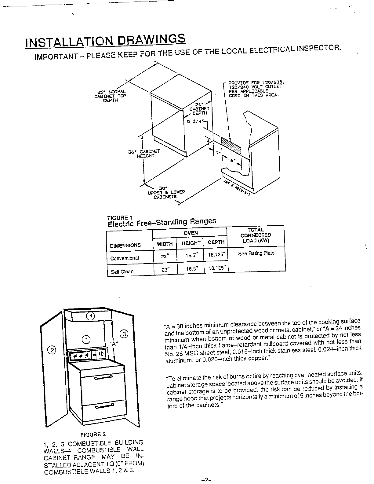
INSTALLATION DRAWINGS
IMPORTANT - PLEASE KEEP FOR THE USE OF THE LOCAL ELECTRICAL INSPECTOR.
1_0/_40 VOLTOUTLET
PER APPLICABLE
CCRO _N T_I$ AREA.
36" 82
HEIGHT I?
CABINETS
FIGURE 1
Electric Fre_--Standing Ranges
OVEN TOTAL
CQNNECTED
DIMEN$ION_ WIDTH HEIGHT DEPTH LOAD(KW]
C(_nventionat 23_' 16.5" 18.'_25" _ee RetingPlate
Self C_ean 23" I 16.5" 18.125"
I
I
_[ "A= 30inches minimum clearance betweenthe tao of thecooking surface
andthebottom of an unprotected wood ormetalcabinet." or"A= 24.inches
,, minimum when bottom of wood or metal cabinet is protected by not less
Q than 1/4_inch thick flame-retardant millboard covered with not less than
No.28 MSG sheetsteel, 0.015-inch thickstainlesssteet,0.024.--4richthick
aluminum, or 0.020-inch thick copper."
_o eliminate the riskof burnsor fire byreachingover heatedsurfaceunits,
i cabinets_orage"spac_,ccated above the surfac_ounits shouldbe avoided,if
cabinet storage is to be provided, the risk can be reduced by installing a
range hoodthatprojects horizontallya minimumof5inchesbeyondthebot-
_ tom of the cabinets."
FIGURE 2
1, 2, 3 COMBUSTIBLE BUILDING
WALLS--.4 COMBUSTIBLE WALL
CABINET-RANGE MAY BE IN-
STALLED ADJACENTTQ (0" FROM)
COMBUSTIBLE WALLS 1, 2 & 3.
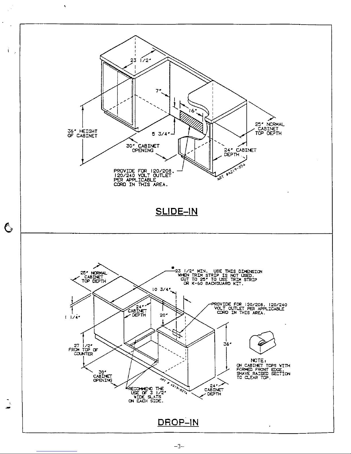
SLIDE-IN
DROpLIN
 Loading...