

Installation Instructions and
Use and Care Guide
30" (76.2 cm)
36" (91.4 cm)
42" (106.7 cm)
48" (121.9 cm)
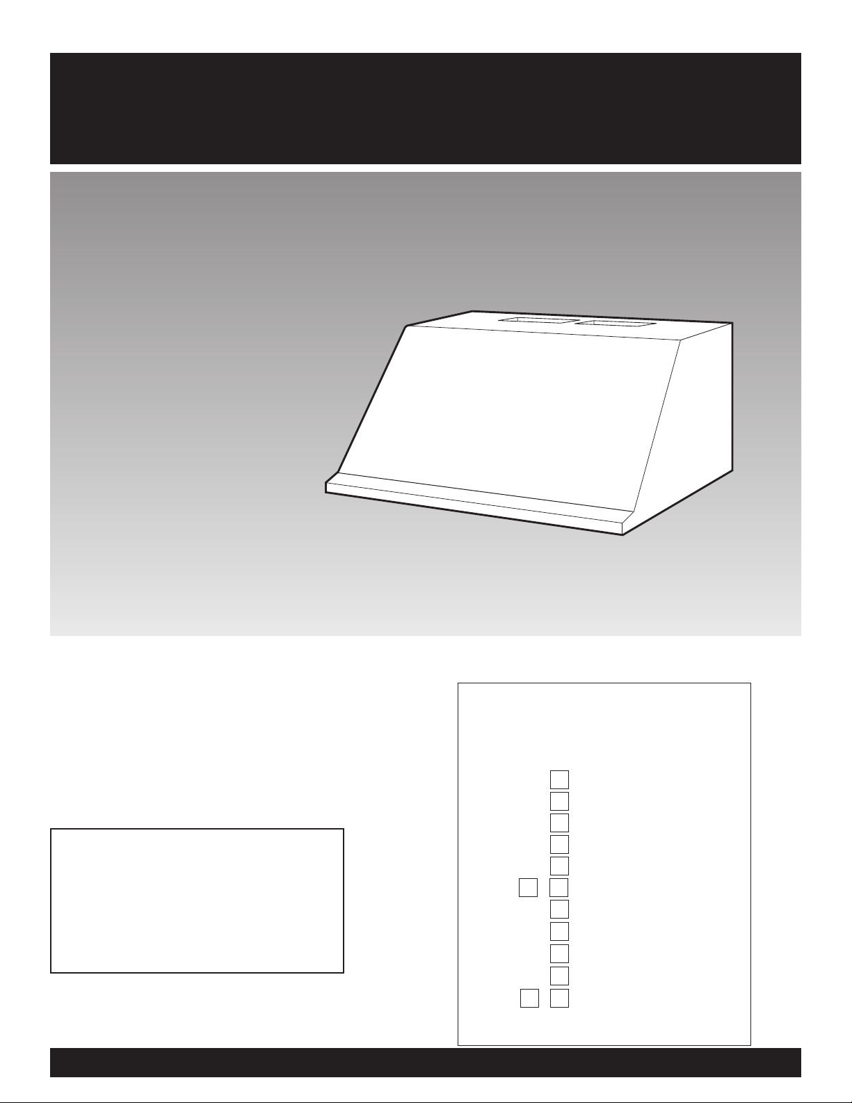
Wall-Mount
Pro Line
™
Range Hood
IMPORTANT:
Read and save
these instructions.
IMPORTANT:
Installer: Leave Installation Instructions with
the homeowner.
Homeowner: Keep Installation Instructions for
future reference.
Save Installation Instructions for local electrical
inspector's use.
Part No. 4329454/8285147
Pièce N° 4329454/8285147
Quick Reference
Table of Contents:
Pages
Before you start
Product dimensions
Cabinet dimensions
Venting requirements
Electrical requirements
Installation steps
Use and Care Information
Wiring diagrams
Accessories
Warranty
Requesting Assistance
or Service
2
3
3
3
5
5 - 7
8
9
9
10
11 - 12
Before you start...
Proper installation is your responsibility:
• Have a qualified technician install this
range hood.
• Comply with installation clearances
specified on the model/serial rating
plate.
The model/serial rating plate is located
inside the range hood on the rear wall.
Range hood location should be away from
strong draft areas, such as windows, doors
and strong heating vents.
Cabinet opening dimensions that are
shown must be used. Given dimensions
provide minimum clearance. Consult
your cooktop/range manufacturer
installation instructions before making
any cutouts.
Grounded electrical outlet is required.
See “Electrical requirements.”
The canopy hood is factory set for
venting through the roof or wall. To vent
directly through the wall, the blower
must be rotated to face the rear of the
range hood.
All openings in ceiling and wall where
range hood will be installed must be
sealed.
Important: Observe all governing
codes and ordinances.
This is the safety alert symbol.
This symbol alerts you to
potential hazards that can kill
or hurt you and others. All safety
messages will follow the safety alert
symbol and either the word “DANGER”
or “WARNING”. These words mean:
You can be killed or seriously injured
if you don’t follow instructions.
DANGER
WARNING
Your safety and the safety of
others is very important.
We have provided many important
safety messages in this manual and
on your appliance. Always read and
obey all safety messages.
All safety messages will tell you what
the potential hazard is, tell you how to
reduce the chance of injury, and tell
you what can happen if the
instructions are not followed.
You can be killed or seriously injured
if you don’t immediately
follow
instructions.
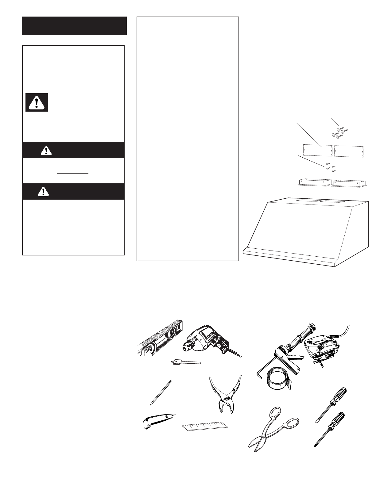
Parts supplied:
Damper:
30” (76.2 cm) = 1
36” (91.4 cm) = 1
42” (106.7 cm) = 1
48” (121.9 cm) = 2
canopy
Parts needed:
• 2 U.L.- or C.S.A.- listed, 1/2" (12.5 mm)
conduit connectors
• power supply cable
• 1 wall or roof cap
• metal vent system
Tools needed:
Phillips
screwdriver
flat-blade
screwdriver
caulking gun and
weatherproof
caulking
compound
duct tape
metal
snips
pliers
pencil
saber or
keyhole saw
drill
1-1/4" drill bit
level
measuring
tape or ruler
wire stripper
or utility knife
WARNING — TO REDUCE THE
RISK OF FIRE, ELECTRIC
SHOCK, OR INJURY TO
PERSONS, OBSERVE THE
FOLLOWING:
Installation work and electrical
wiring must be done by qualified
person(s) in accordance with all
applicable Codes and Standards,
including fire related construction.
Sufficient air is needed for proper
combustion and exhausting of
gases through the flue (chimney)
of fuel burning equipment to
prevent back drafting. Follow the
heating equipment
manufacturer’s guideline and
safety standards such as those
published by the National Fire
Protection Association
(NFPA),and the American Society
of Heating Refrigeration and Air
Conditioning Engineers
(ASHRAE), and the local code
authorities.
When cutting or drilling into wall
or ceiling, do not damage
electrical wiring and other hidden
utilities.
Ducted fans must always be
vented to the outdoors.
WARNING — To reduce the r isk
of fire, use only metal ductwork.
This unit must be grounded.
2
Mounting screws
30” (76.2 cm) = 2
36” (91.4 cm) = 2
42” (106.7 cm) = 4
48” (121.9 cm) = 4
Damper screws:
30” (76.2 cm) = 2
36” (91.4 cm) = 2
42” (106.7 cm) = 2
48” (121.9 cm) = 4
Exhaust outlet cover
30” (76.2 cm) = 1
36” (91.4 cm) = 1
42” (106.7 cm) = 1
48” (121.9 cm) = 2
Note: Backsplash, vent cover, discharge
transition, and chimney extension kits are
available from your dealer (see page 9). These
are required for some installations and must
be installed at time of hood installation as
shown in the Installation Instructions.
3
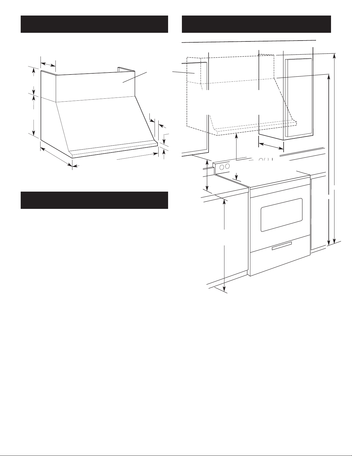
Cabinet dimensions
Product dimensions
Venting requirements
• The size of the vent should be uniform.
• Use no more than three 90° elbows.
• Make sure there is a minimum of 24" (61 cm) of straight
vent between the elbows if more than one elbow is used.
• Do Not install two elbows together.
• The length of vent system and number of elbows should
be kept to a minimum to provide efficient performance.
• The vent system must have a damper. If roof or wall cap
has a damper, Do Not use damper supplied with the
range hood.
• Use duct tape to seal all joints in the vent system.
• Use caulking to seal exterior wall or roof opening around
the cap.
Determine which venting method is best for your
application and follow “Preparation” under ”Installation
steps“ on Page 5.
For the most efficient and
quiet operation:
Vent system must terminate to the outside.
Do not terminate the vent system in an attic or other
enclosed area.
Do not use 4-inch (10.2 cm) laundry-type wall caps.
Use metal vent only. Rigid metal vent is recommended. Do
not use plastic or metal foil vent.
30" (76.2 cm) hood: 29-7/8" (75.9 cm)
36" (91.4 cm) hood: 35-7/8" (91.1 cm)
42" (106.7 cm) hood: 41-7/8" (106.4 cm)
48" (121.9 cm) hood: 47-7/8" (121.6 cm)
25-3/16"
(64 cm)
12-1/32"
(30.6 cm)
2-7/32"
(5.6 cm)
1-3/8"
(3.5 cm)
36" (91.4 cm)
base cabinet
height
30" (76.2 cm) hood: 30" (76.2 cm)
36" (91.4 cm) hood: 36" (91.4 cm)
42" (106.7 cm) hood: 42" (106.7 cm)
48" (121.9 cm) hood: 48" (121.9 cm)
min. cabinet opening widths
30" (76.2 cm) min. bottom of
canopy to cooking surface
12"
(30.5 cm)
18-3/16"
(46.2 cm)
canopy
13" (33 cm)
cabinet depth
For installations with canopy only, minimum of
84-3/16" (213.8 cm).
For installations with optional vent hood cover, minimum
of 96-3/16" (244.3 cm).
Ceiling height above canopy or canopy with optional vent
hood is unlimited.
18" (45.7 cm)
min.
clearance
upper
cabinet to
countertop
vent cover
(if used)
Vent Piece 3-1/4" x 10" (8.3 cm x 25.4 cm) 7" (17.8 cm), 8" (20.3 cm),
Rectangular 9" (22.9 cm), 10" (25.4 cm)
Round
45° elbow 7.0 feet 2.5 feet
(2.1 m) (0.8 m)
90° elbow 5.0 feet 5.0 feet
(1.5 m) (1.5 m)
90° flat elbow 12.0 feet
(3.7 m)
transition to round 5.0 feet
(1.5 m)
wall cap 0.0 feet
(0.0 m)
4
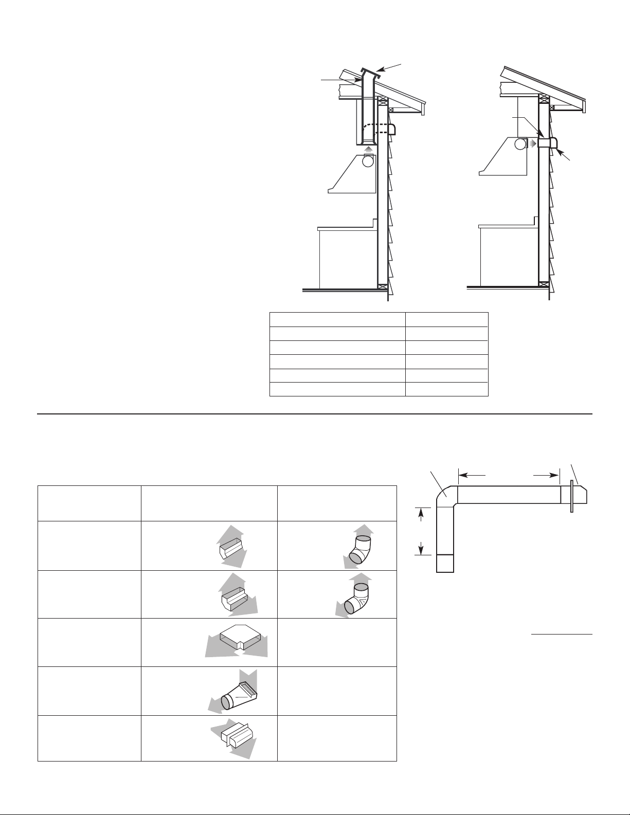
Venting methods
This canopy range hood is factory set for
vertical venting. For rear vent applications, the
blower must be turned inside the range hood so
that the blower vents to the rear as indicated.
The blower is turned by removing two screws
on each side of the blower, rotating the blower
with the exhaust opening facing the rear and
then replacing the screws. The exhaust cover(s)
must be moved to block the unused opening(s).
The blower must be converted before installing
the range hood.
Vent system needed for installation is not
included. The 30" (76.2 cm), 36" (91.4 cm) and
42" (106.7 cm) models have one exhaust
opening. 3-1/4" x 10" (8.3 cm x 25.4 cm)
rectangular, 7" (17.8 cm) round, 8" (20.3 cm)
round, 9" (22.9 cm) round, or 10" (25.4 cm)
round vent may be used. The hood exhaust
opening is 3-1/4" x 10" (8.3 cm x 25.4 cm).
The 48" (121.9 cm) model has two 3-1/4" x 10"
(8.3 cm x 25.4 cm) exhaust openings. It is
recommended that Vent Transition Kit No.
8284757 be used to transition the two openings
into one 10" (25.4 cm) round vent. (Cannot be
used with Chimney Extension Kit No. 8284754.)
Vent system can terminate either through the
roof or wall.
The vent system length should not exceed the
lengths shown in the chart.
Vent size Maximum length
3-1/4" x 10" (8.3 cm x 25.4 cm) 35 ft. (10.7 m)
7" (17.8 cm) round 40 ft. (12.2 m)
8" (20.3 cm) round 50 ft. (15.2 m)
9" (22.9 cm) round 60 ft. (18.3 m)
10" (25.4 cm) round 60 ft. (18.3 m)
3-1/4" x 10”
(8.3 cm x 25.4 cm)
elbow
wall
cap
Maximum length = 35 ft. (10.7 m)
1 — 90° elbow = 5 ft. (1.5 m)
8 ft. (2.4 m) straight = 8 ft. (2.4 m)
1 — wall cap = 0 ft. (0 m)
Length of 3-1/4" x 10"
(8.3 cm x 25.4 cm)
system = 13 ft. (3.9 m)
6 ft. (1.8 m)
2 ft.
(0.6 m)
Example for 3-1/4" x 10"
(8.3 cm x 25.4 cm) v
ent system
To calculate the length of the system you need, add the equivalent feet (meters)
for each vent piece used in the system.
Note: Flexible vent is Not
recommended.
Flexible vent creates back pressure
and air turbulence that greatly
reduces performance.
Calculating the vent system length
3-1/4" x 10"
(8.3 cm x 25.4 cm)
vertical venting
(roof or wall)
roof cap
Horizontal venting
3-1/4" x 10"
(8.3 cm x 25.4 cm)
horizontal venting
wall cap
Vertical venting

Electrical requirements
Installation steps
Important: Observe all governing
codes and ordinances.
It is the customer’s responsibility:
•To contact a qualified electrical
installer.
•To assure that the electrical
installation is adequate and in
conformance with National
Electrical Code, ANSI/NFPA 70
— latest edition*, or CSA
Standards C22.1-94, Canadian
Electrical Code, Part 1 and
C22.2 No.0-M91 - latest
edition** and all local codes
and ordinances.
If codes permit and a separate
ground wire is used, it is
recommended that a qualified
electrician determine that the
ground path is adequate.
A 120-volt, 60-Hz, AC-only, fused
electrical system is required on a
The range hood must be connected
with copper wire only.
The range hood should be
connected directly to the fused
disconnect (or circuit breaker) box
through flexible armored or
nonmetallic sheathed copper cable.
A U.L.- or C.S.A.-listed strain relief
must be provided at each end of the
power supply cable. Wire sizes
separate 15-amp circuit, fused on
both sides of the line.
Do not ground to a gas pipe.
Check with a qualified electrician if
you are not sure range hood is
properly grounded.
Do not have a fuse in the neutral or
ground circuit.
IMPORTANT:
Save Installation Instructions for
electrical inspector’s use.
(COPPER WIRE ONLY) and
connections must conform with the
rating of the appliance as specified
on the model/serial rating plate.
Wire sizes must conform to the
requirements of the National
Electrical Code ANSI/NFPA 70 —
latest edition*, or CSA Standards
C22.1-94, Canadian Electrical Code
Part 1 and C22.2 No. 0-M91 - latest
edition** and all local codes and
ordinances.
A U.L.- or C.S.A.-listed conduit
connector must be provided at each
end of the power supply cable (at the
range hood and at the junction box).
Copies of the standards listed may be
obtained from:
* National Fire Protection Association
One Batterymarch Park
Quincy, Massachusetts 02269
** CSA International
8501 East Pleasant Valley Road
Cleveland, Ohio 44131-5575
It is recommended that the vent system be installed
before hood is installed.
Do not cut a joist or stud unless absolutely necessary. If a
joist or stud must be cut, then a supporting frame must
be constructed.
Before making cutouts, make sure there is proper
clearance within the ceiling or wall for exhaust vent.
Check that all the installation parts and the box with
filters have been removed from the shipping carton.
1. If possible, disconnect and move freestanding or
slide-in range from cabinet opening to provide easier
access to rear wall. Otherwise put a thick, protective
covering over countertop, cooktop or range to protect
from damage or dirt. Select a flat surface for assembling
the unit. Cover that surface with a protective covering and
place all hood parts and hardware in it.
2. Determine and mark the centerline on the wall
where the hood will be installed. If the vent system is
already installed, use centerline of vent opening.
3. If venting horizontally out the back of hood and vent
system is not installed, mark and cut vent opening now.
4.
Important: If used, Backsplash Kit must be
installed before installing the hood.
If a backsplash is not used, go to Step 5.
Backsplash installation: (The hardware package
supplied with the kit includes 4 plastic wall anchors
and mounting screws.)
• The height of the backsplash will determine the height
Preparation
Extends from
19-23/32" (50.1 cm)
to 39" (99.1 cm)
3/8" (9.5 mm)
top of backsplash
corner
mounting
hole (4)
1" (25.4 mm)
29-7/8" (75.9 cm)
35-7/8" (91.1 cm)
41-7/8" (106.4 cm)
47-7/8" (121.6 cm)
of the hood. Note: The minimum height of the hood
above the cooktop, as shown on Page 3, is 30"
(76.2 cm). The backsplash can be extended from
19-23/32" (50.1 cm) to 39" (99.1 cm). Note: As the 30"
(76.2 cm) installation height increases, the hood's
capture area decreases.
• Determine the height of the hood.
• Position the hood on the wall so that the top of the
backsplash is at the height of the bottom edge of
hood. Mark the location of the four corner holes. It is
recommended that the backsplash be attached to the
wall at all four corners. However, the lower flange
can be secured between the wall and backsplash,
countertop or cabinet base without using the bottom
corner screws.
• Drill 5/16" (8 mm) holes.
• Push the plastic wall anchors all the way into the holes.
• Position the holes in the backsplash over the wall
anchors and attach using the screws supplied.
5
5.The hood attaches to the wall
with the mounting screws located
as shown. For the 30" (76.2 cm) and
36" (91.4 cm) models, there are two
mounting screws. For the 42"
(106.7 cm) and 48" (121.9 cm)
models, there are four mounting
screws. Install the screws into the
wall until the screw heads are tight
against the wall and horizontal.
Note:The screws provided for
mounting this range hood must be
fastened into solid wood. Do Not
fasten into sheet rock only.
6
)
30" (76.2 cm) hood
36" (91.4 cm) hood
42" (106.7 cm) hood
48" (121.9 cm) hood
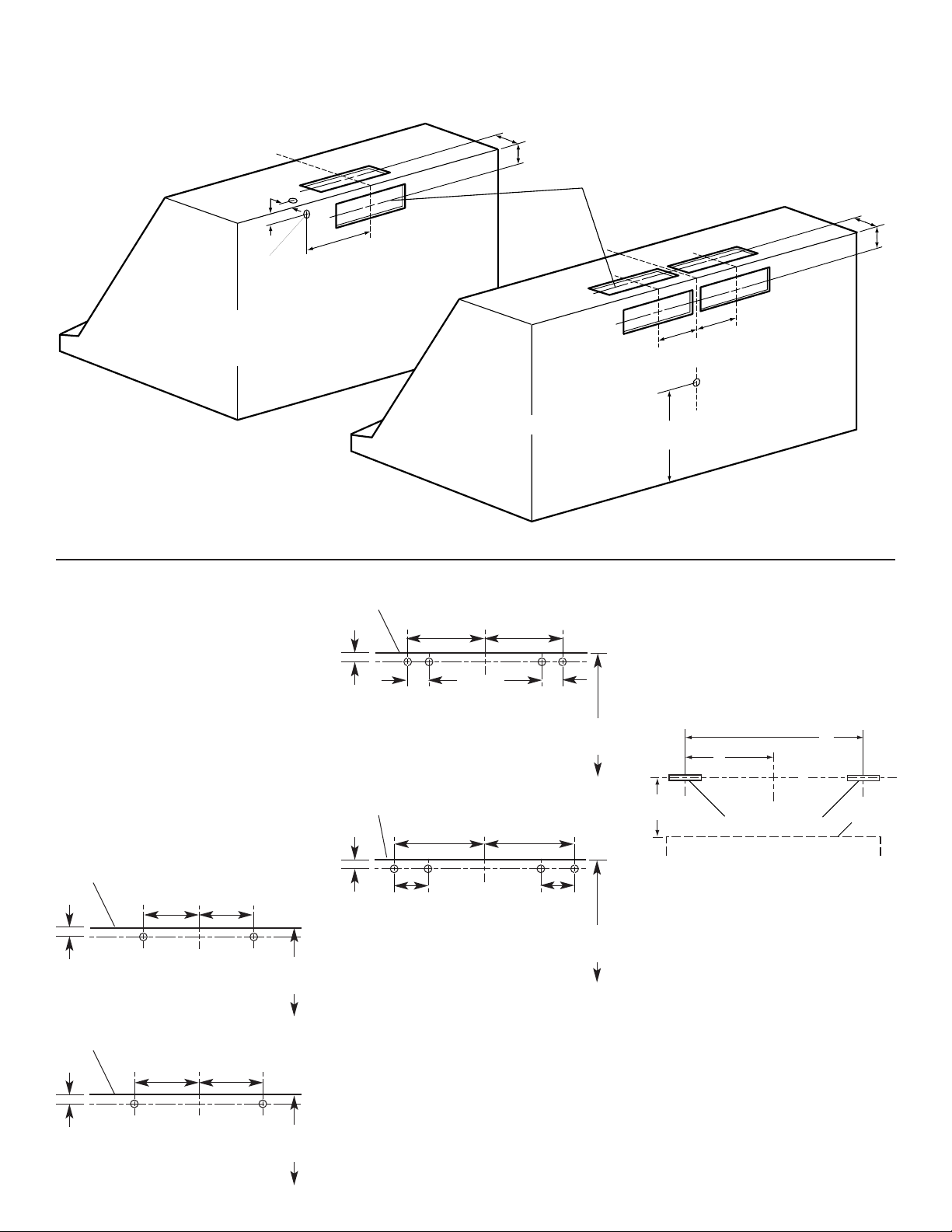
Vent and Electrical openings
5a. Optional vent cover
installation: Attach the full-width vent
cover to the top of the range hood
with the screws provided. The vent
cover must be attached to the top of
the range hood before mounting the
range hood to the wall.
Install each bracket on the wall as
shown. Make sure that the screws
and brackets are securely fastened to
the wall.
Install only the brackets. Do not
install the hood.
top of hood
1-1/16"
(17.5 cm)
12-9/16"
(31.9 cm)
12-9/16"
(31.9 cm)
48" (121.9 cm)
min. to cooking
surface
top of hood
1-1/16"
(17.5 cm)
15-9/16"
(39.5 cm)
15-9/16"
(39.5 cm)
48" (121.9 cm)
min. to cooking
surface
top of hood
1-1/16"
(17.5 cm)
21-9/16"
(54.9 cm)
21-9/16"
(54.9 cm)
7"
(17.8 cm)
7"
(17.8 cm)
48" (121.9 cm)
min. to cooking
surface
48" (121.9 cm) hood
top of hood
1-1/16"
(17.5 cm)
18-9/16"
(47.2 cm)
4-1/4"
(10.8 cm)
4-1/4"
(10.8 cm)
42" (106.7 cm) hood
18-9/16"
(47.2 cm)
48" (121.9 cm)
min. to cooking
surface
30" (76.2 cm) hood
36" (91.4 cm) hood
C
L
1-1/8"
(2.9 cm)
Electrical
opening
9-11/16"
(24.6 cm)
2-7/8"
(7.5 cm)
2-7/8"
(7.5 cm)
All vent openings are
3-1/4" x 10" (8.3 cm x 25.4 cm)
6-3/32"
(15.5 cm)
Electrical opening
C
10-1/2"
(26.7 cm)
L
6-3/32"
(15.5 cm)
2-7/8"
(7.5 cm)
2-7/8"
(7.5 cm
B
A
C
L
11"
(27.9 cm)
A
30" (76.2 cm) hood: 13-15/32" (34.2 cm)
36" (91.4 cm) hood: 16-15/32" (41.8 cm)
42" (106.7 cm) hood: 19-15/32" (49.4 cm)
48" (121.9 cm) hood: 22-15/32" (57.1 cm)
B
30" (76.2 cm) hood: 26-15/16" (68.4 cm)
36" (91.4 cm) hood: 32-15/16" (83.7 cm)
42" (106.7 cm) hood: 38-15/16" (98.9 cm)
48" (121.9 cm) hood: 44-15/16" (114.1 cm)
C
L
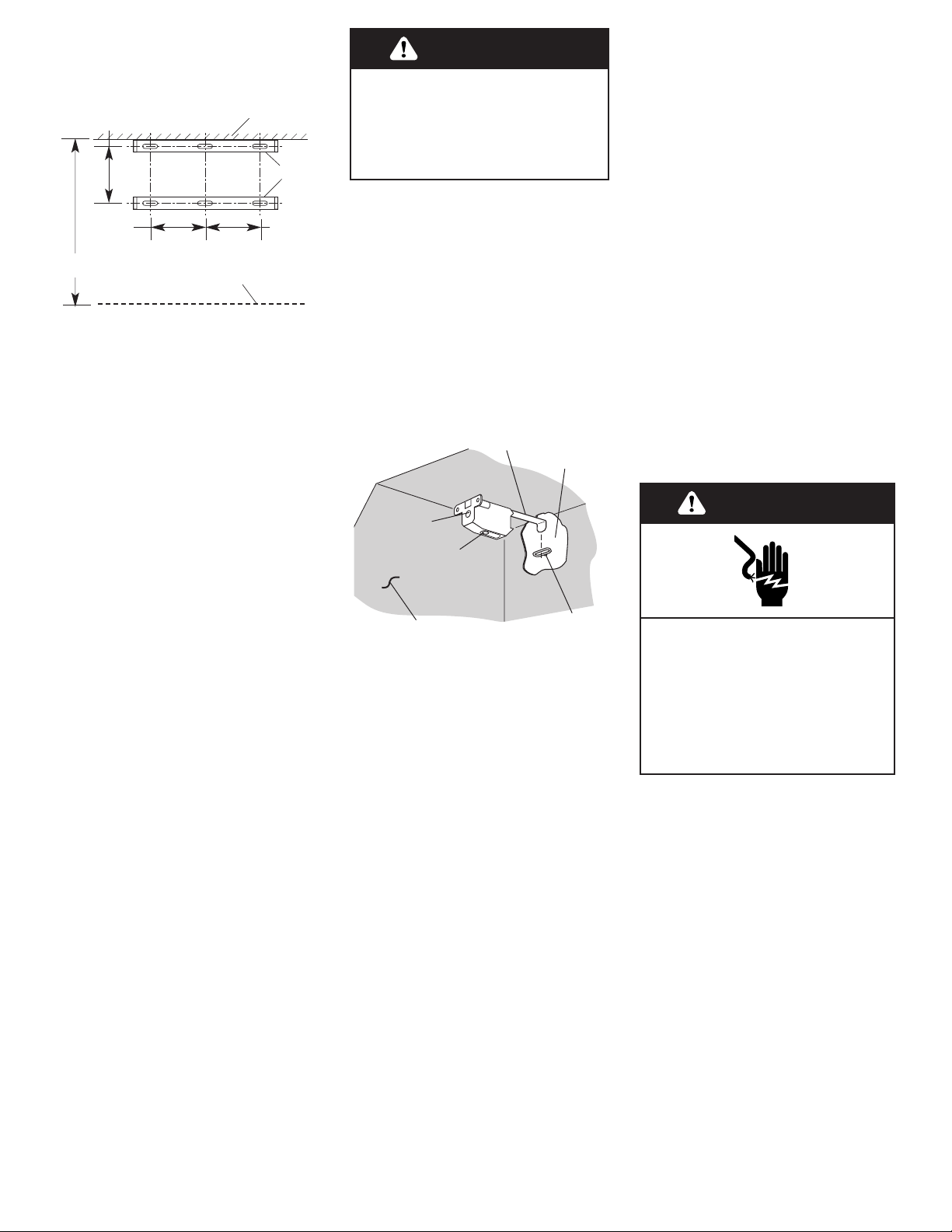
Mounting brackets
Top
of hood
7
9. If roof or wall cap does not
have a damper, attach damper to
exhaust opening(s) on top of the
hood using two Phillips-head
screws.
10. If 48" (121.9 cm) hood is to
be connected to 10" (25.4 cm) round
vent system, install the vent
transition piece now.
Electrical
connection
Electrical Shock Hazard
Disconnect power before making
electrical connections.
Connect ground wire to green
ground screw in terminal box.
Failure to do so can result in
death or electrical shock.
WARNING
15 . Make electrical connection:
Connect the power supply cable
to hood terminal box through
the U.L.- or C.S.A.-listed conduit
connector.
Connect the white wire of the
power supply cable with the
white lead in the hood using a
twist-on connector; connect the
black wire of the power supply
cable with the black lead in the
hood using a twist-on
connector.
Connect the power supply green
ground wire under the green,
ground screw.
Tighten conduit connector
screws.
Replace the terminal box cover.
12 . The brackets are also used
to adjust the level of the canopy.
Using a Phillips screwdriver, rotate
the screw V2 to adjust the level of
the canopy.
13 . Connect vent system to
hood. Seal all joints with duct tape.
14 . If your installation uses the
optional vent cover, fit the cover
flanges over the brackets. If
installation uses the chimney
extension, fit the extension over the
brackets. Install the upper section
first, then fit the lower section over
the upper section. Seal extension to
hood with duct tape.
6. Determine and make all
necessary cuts in the wall for the
vent system. Install the vent system
before the canopy hood. See venting
methods on Page 4, and hood vent
opening dimensions on Page 6.
7. Determine the required height
for the power supply cable and cut
a 1-1/4" (3.2 cm) hole at this
location. Run wire through hole
according the National Electrical
Code or CSA Standards and local
codes and ordinances. There must
be enough power supply cable
from the fused disconnect (or
circuit breaker) box to make the
connection in the hood’s electrical
box.
Use caulking to seal all openings.
Do Not turn on power until
installation is completed.
8. Remove the terminal box
cover from the canopy hood.
Remove the power supply cable
knockout using a flat-blade
screwdriver. Attach conduit
connector into power supply cable
opening so that conduit connector
clamping screws are inside of
canopy hood.
Excessive Weight Hazard
Use two or more people to move
and install range hood.
Failure to do so can result in
back or other injury.
WARNING
30" (76.2 cm) hood has two brackets
36" (91.4 cm) hood has two brackets
42" (106.7 cm) hood has four brackets
48" (121.9 cm) hood has four brackets
11. The hood attaches to the
wall by screws discussed earlier in
the installation instructions at
Step 5. The hood hangs from these
screws by brackets inside the
range hood. Before attempting to
hang the hood, use a Phillips
screwdriver to rotate the
adjustment screw marked V1
counterclockwise to extend the
brackets from the canopy.
Hang the range hood by inserting
the brackets into the mounting
screws as shown. Note: These
screws must be installed into solid
wood to support the weight of the
hood as described in Step 5. Rotate
the screws marked V1 to tighten
the range hood against the wall.
Make sure that the range hood is
securely tightened against the
wall.
5b. If chimney extension is
used: Attach the extension brackets
as shown.
Make sure that the screws are
securely fastened to the wall.
10-5/8"
(27 cm)
8-1/8"
(20.6 cm)
8-1/8"
(20.6 cm)
brackets
top of hood
ceiling
23" (58.4 cm) max.
12" (30.5 cm) min.
V1
V2
bracket
wall
mounting
screw
hood
8
Use and Care Information
WARNING — To reduce the risk of
fire or electrical shock, do not use
this fan with any solid-state speed
control device.
WARNING — TO REDUCE THE
RISK OF FIRE, ELECTRIC SHOCK,
OR INJURY TO PERSONS,
OBSERVE THE FOLLOWING:
Use this unit only in the manner
intended by the manufacturer. If
you have questions, contact the
manufacturer. Before servicing or
cleaning unit, switch power off at
service panel and lock the service
disconnecting means to prevent
power from being switched on
accidentally. When the service
disconnecting means cannot be
locked, securely fasten a
prominent warning device such as
a tag to the service panel
CAUTION: For general ventilating
use only. Do not use to exhaust
hazardous or explosive materials
and vapors.
WARNING — TO REDUCE THE
RISK OF A RANGE TOP GREASE
FIRE:
Never leave surface units
unattended at high settings.
Boilovers cause smoking and
greasy spillovers that may ignite.
Heat oils slowly on low or
medium settings.
Always turn hood ON when
cooking at high heat or when
cooking flaming foods.
Clean ventilating fans frequently.
Grease should not be allowed to
accumulate on fan or filter.
Use proper pan size. Always use
cookware appropriate for the size
of the surface element.
WARNING — TO REDUCE THE
RISK OF INJURY TO PERSONS IN
THE EVENT OF A RANGE TOP
GREASE FIRE, OBSERVE THE
FOLLOWING:
SMOTHER FLAMES with a closefitting lid, cookie sheet, or metal
tray, then turn off the burner. BE
CAREFUL TO PREVENT BURNS. If
the flames do not go out
immediately, EVACUATE AND
CALL THE FIRE DEPARTMENT.
NEVER PICK UP A FLAMING PAN
— You may be burned.
DO NOT USE WATER, including
wet dishcloths or towels — a
violent steam explosion will
result. Use an extinguisher ONLY
if:
You know you have a Class ABC
extinguisher, and you already
know how to operate it.
The fire is small and contained in
the area where it is started.
The fire department is being
called.
You can fight the fire with your
back to an exit.
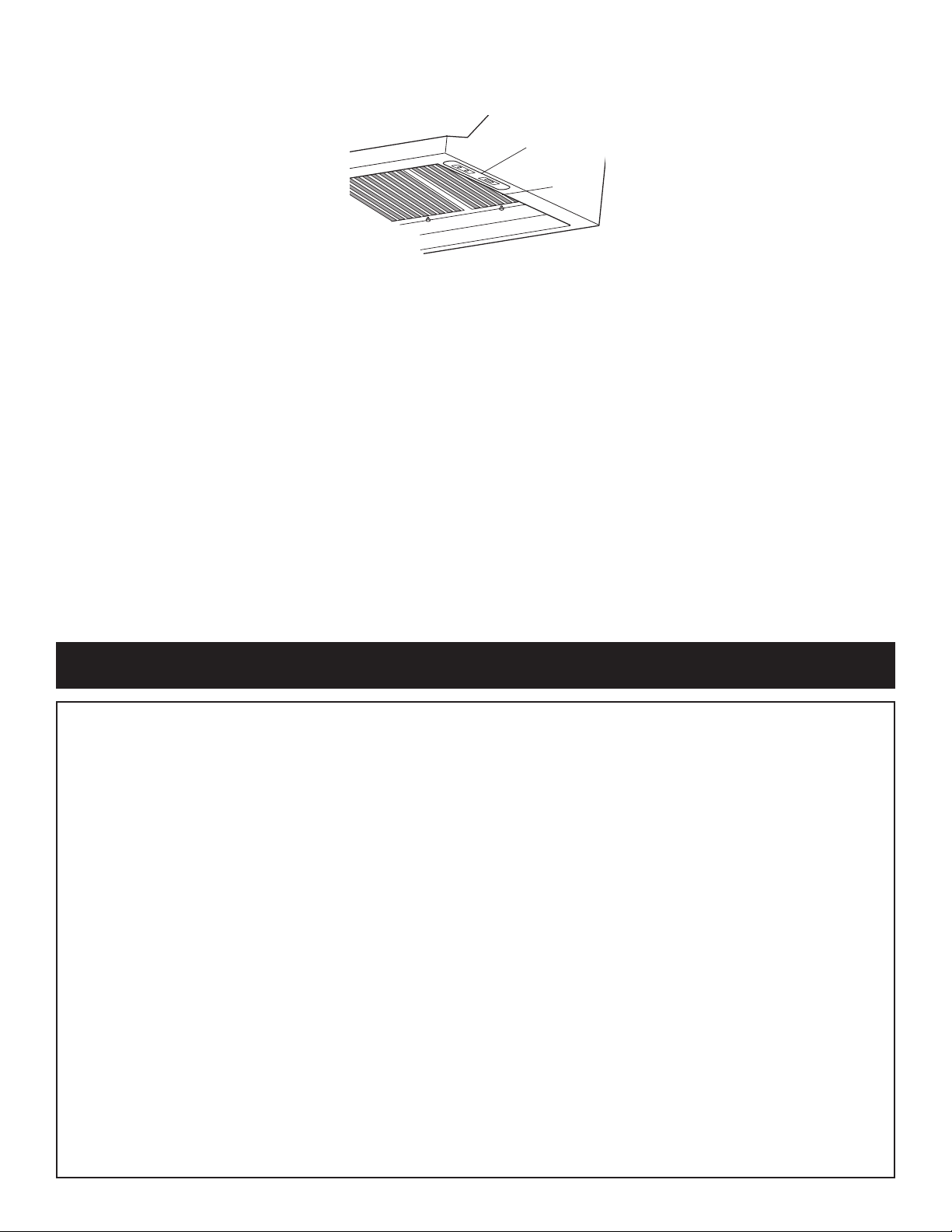
19. Check the operation of
the range hood:
Move light switch to
“1” position. The light should
turn on.
Move blower switch to
“1” position. The blower
should operate.
Move the blower speed switch
to: “1” position for low speed,
“2” position for medium
speed, or “3” position for high
speed.
Move blower and light
switches to “0” position to
turn blower and light off.
16 . Install the filters.
• Remove the filters from the box
and remove the white protective
coating from the filters.
Note: Use two hands to install
filter, one to pull and turn the
knob, the other to hold the filter
in place so that it doesn’t fall
onto the cooktop.
• Grasp one of the filters so that
the knob faces down and toward
the back of the hood.
• Insert the filter end without the
knob into the retaining channel
in the front of the hood.
• Pull and turn the knob to the left
(counterclockwise) so that the
locking lever does not protrude
from the filter.
• Insert the knob end of the filter
into the retaining channel in the
back of the hood.
• Turn the knob to the right
(clockwise) to lock the filter in
place.
• Repeat for remaining filters.
Check operation
17. Turn power on.
To g et the most efficient
use from your new range
hood, read the “Use and
Care Information” section.
Keep your KitchenAid
Installation Instructions and
Use and Care Guide close
to range hood for easy
reference.
controls
filters
18. The canopy hood
controls are located on the righthand underside of the canopy.
If range hood does not operate:
Check that the circuit breaker
is not tripped or the house
fuse blown.
Disconnect power supply.
Check that wiring is correct.

Opening the canopy hood
control panel:
The hood controls are located on
the right-hand underside of the
canopy.
Operating the light:
ON: Move the light switch to the
“1” position.
OFF: Move the light switch to the
“0” position.
Operating the blower:
ON: Move the blower switch to
the “1” position.
OFF: Move the blower switch to
the “0” position.
Adjusting the blower speed:
The blower has three speed
control.
Move the blower speed switch to:
“1” position for low speed,
“2” position for medium speed,
or “3” position for high speed.
Replacing the Halogen
lamps:
Cleaning
Filters:
The filters should be washed
frequently. Place metal filters in
dishwasher or hot detergent
solution to clean.
To remove filters:
Note: Use two hands to remove
filters, one to pull and turn the
knob, the other to hold the filter
so that it doesn’t fall onto the
cooktop.
• Pull knob forward, toward the
front of the hood, while turning
the knob to the left (counterclockwise) to release the locking
lever.
To reinstall filters, see Step 16.
Exterior surfaces:
• Do not use steel wool or soapfilled scouring pads.
• Rub in direction of the grain line
to avoid marring the surface.
• Always wipe dry to avoid water
marks.
• KitchenAid®Professional
Formula Stainless Steel Cleaner
&Polish is the cleaner
recommended for cleaning
stainless steel surfaces on this
product. To order call our
Customer Service Center at
1-800-442-9991 or order on-line at
www.applianceaccessories.com
and ask for part number
8171420. To order from Canada,
call 1-800-807-6777.
• If commercial cleaners are used,
follow label directions. Do not
use products that contain
chlorine (bleach). Chlorine is a
corrosive substance.
For routine cleaning and
fingerprints, use liquid detergent
soap and water, or all-purpose
cleaner. Wipe with damp cloth or
sponge, then rinse with clean
water and wipe dry.
Optional Installation Kits available from your dealer.
Note: Kits are available in stainless steel only.
Backsplash: Must be installed before hood is installed.
30" (76.2 cm) hood: Kit No. 8285148
36" (91.4 cm) hood: Kit No. 8284756
42" (106.7 cm) hood: Kit No. 8284827
48" (121.9 cm) hood: Kit No. 8284755
Vent covers: 12" (30.5 cm) high, 12" (30.5 cm) deep.
30" (76.2 cm) hood: Kit No. 8285149
36" (91.4 cm) hood: Kit No. 8284753
42" (106.7 cm) hood: Kit No. 8284828
48" (121.9 cm) hood: Kit No. 8284752
Chimney extensions: extends from 12" (30.5 cm) to
23" (58.4 cm) high. For use with 30" (76.2 cm), 36"
(91.4 cm), 42" (106.7 cm) and 48" (121.9 cm) hoods:
Kit No. 8284754
Vent transition: transitions from two 3-1/4" x 10"
(8.3 x 25.4 cm) vents to one 10" (25.4 cm) round vent.
Not for use with chimney extension Kit No. 8284754.
30" (76.2 cm) hood: Not available
36" (91.4 cm) hood: Not available
42" (106.7 cm) hood: Not available
48" (121.9 cm) hood: Kit No. 8284757
light
switch
blower
switch
blower speed
switch
Installation kits
available from your dealer
9
controls
Operation
The canopy hood is designed to
remove smoke, cooking vapors
and odors from the cooktop area.
For best results, start the hood
before cooking and allow it to
operate several minutes after the
cooking is complete to clear all
smoke and odors from the kitchen.
Before you begin, make sure that
the range hood is turned off and
that the other lamps have had
sufficient time to cool. Halogen
bulbs burn extremely hot.
To replace a halogen lamp:
• Remove 2 screws from the
circular metal trim around the
lamp assembly.
• Pull the trim with the lamp
assembly attached down far
enough so that the lamp can be
pushed out of the socket.
• Insert the new lamp into the
socket and push the lamp and
trim assembly back up into the
hood.
• Replace the trim.
36" (91.4 cm) and 42" (106.7 cm) hoods
shown.

Warranty
KitchenAid®Range Hood Warranty
LENGTH OF WARRANTY KitchenAid WILL PAY FOR
LIMITED ONE-YEAR WARRANTY Labor and any parts of your range hood (except light bulbs and
From Date of Purchase filters) which are defective in materials or workmanship.
KitchenAid WILL NOT PAY FOR
A. Consumable parts such as light bulbs and filters.
B. Service calls to:
1. Correct the installation of the range hood.
2. Instruct you how to use the range hood.
3. Replace house fuses or correct house wiring.
C. Repairs when range hood is used in other than normal, single-family household use.
D. Pickup and delivery. This product is designed to be repaired in the home.
E. Damage to range hood caused by accident, misuse, fire, flood, act of God or use of products not approved
by KitchenAid.
KITCHENAID AND KITCHENAID CANADA DO NOT ASSUME ANY RESPONSIBILITY FOR INCIDENTAL OR
CONSEQUENTIAL DAMAGES. Some states or provinces do not allow the exclusion or limitation of incidental or
consequential damages, so this exclusion or limitation may not apply to you.
This warranty gives you specific legal rights, and you may also have other rights which may vary from state to
state or province to province.
Outside the United States and Canada, a different warranty may apply. For details, please contact your
authorized KitchenAid dealer.
If you need service, first see the “Check Operation” section of this book. After checking the “Check Operation,”
additional help can be found by checking the “Requesting Assistance or Service” section or by calling our
KitchenAid Customer Interaction Center, 1-800-235-0665 (toll-free), from anywhere in the U.S.A. or Canada.
10
Wiring diagrams
For 30" (76.2 cm), 36" (91.4 cm)
and 42" (106.7 cm) hoods
For 48" (121.9 cm) hoods

11
Requesting Assistance or Service
Call the KitchenAid Customer Interaction
Center toll-free at 1-800-235-0665.
Our consultants are available to assist you.
When calling: Please know the purchase date, and
the complete model and serial number
of your appliance This information will
help us better respond to your request.
Our consultants provide assistance with:
•
Features and specifications on our full line
of appliances
•
Installation information
If you need replacement parts
If you need to order replacement parts, we recommend that you only use factory-authorized parts.
These parts will fit right and work right, because
they are made to the same exacting specifications
used to build every new KitchenAid* appliance.
To locate factory-authorized parts in your area, call
our Customer Interaction Center telephone number,
your nearest authorized service center, or KitchenAid
Factory Service at 1-800-442-1111.
For further assistance
If you need further assistance, you can write to
KitchenAid with any questions or concerns at:
KitchenAid Brand Home Appliances
Customer Interaction Center
c/o Correspondence Dept.
2000 North M-63
Benton Harbor, MI 49022-2692
Please include a daytime phone number in your
correspondence.
•
Use and maintenance procedures
•
Accessory and repair parts sales
•
Specialized customer assistance (Spanish
speaking, hearing impaired, limited vision, etc.)
•
Referrals to local dealers, service companies, and
repair parts distributors
KitchenAid designated service technicians are
trained to fulfill the product warranty and provide
after-warranty service, anywhere in the United
States.
To locate the designated KitchenAid service
company in your area, you can also look in your
telephone directory Yellow Pages.
To avoid unnecessary service calls, please
check the “Check Operation” section. It may
save you the cost of a service call. If you still
need help, follow the instructions below.
If you need assistance or service in U.S.A.

2. If you need service✝...
Contact your nearest KitchenAid Canada Appliance Service branch or authorized servicing
outlet to service your appliance. (See list below.)
Make sure the service company you contact is
authorized to service your appliance during the
warranty period.
1. If the problem is not due to one of the items
listed in “Check Operation”
✝
...
Contact the dealer from whom you
purchased your appliance, or call the
KitchenAid Canada Customer
Interaction Center toll-free,
8:30 a.m. – 6 p.m. (EST),
at 1-800-235-0665.
KitchenAid Canada Appliance Service – Consumer Services
Direct service branches:
BRITISH COLUMBIA 1-800-665-6788
ALBERTA 1-800-661-6291
ONTARIO Ottawa area 1-800-267-3456
(except 807 area code) Outside the Ottawa area 1-800-807-6777
MANITOBA,SASKATCHEWAN 1-800-665-1683
and 807 area code in ONTARIO
QUEBEC Montreal (except South Shore) 1-800-361-3032
South Shore Montreal 1-800-361-0950
Quebec City 1-800-463-1523
Sherbrooke 1-800-567-6966
ATLANTIC PROVINCES 1-800-565-1598
For further assistance
If you need further assistance, you can write to
KitchenAid Canada with any questions or concerns at:
Consumer Relations Department
KitchenAid Canada
1901 Minnesota Court
Mississauga, Ontario L5N 3A7
Please include a daytime phone number in your
correspondence.
✝
When asking for assistance or service, please
provide a detailed description of the problem,
your appliance’s complete model and serial
numbers, and the purchase date. This
information will help us respond properly to
your request.
Before calling for assistance or service, please
check the “Check Operation” section. It may save
you the cost of a service call. If you still need
help, follow the instructions below.
If you need assistance or service in Canada
Requesting Assistance or Service
Part No. 4329454/8285147
Pièce N° 4329454/8285147
© 2002 KitchenAid
® Registered trademark/™ trademark of KitchenAid, U.S.A., KitchenAid Canada licensee in Canada
1/2002
Printed in U.S.A.

Instructions d’installation et
Guide d’utilisation et d’entretien
Hotte d’aspiration pour cuisinière
Pro Line
™
- montage mural
76,2 cm (30 po)
91,4 cm (36 po)
106,7 cm (42 po)
121,9 cm (48 po)
IMPORTANT:
Lire et conserver
ces instructions.
IMPORTANT:
Installateur : Remettre les instructions
d’installation au propriétaire de l’appareil.
Propriétaire : Conserver les instructions
d’installation pour consultation ultérieure.
Conserver les instructions d’installation à
l’intention de l’inspecteur local des installations
électriques.
Pièce N°
4329454/8285147
Référence rapide
Table des matières :
Pages
Avant de commencer...
Dimensions du produit
Dimensions des placards
Circuit de décharge de l’air
Alimentation électrique
Les étapes de l’installation
Utilisation et entretien
Schéma de câblage
Accessoires
Garantie
Demande d'assistance ou
de service
2
3
3
3
5
5 - 7
8
9
9
10
11 - 12

Avant de
commencer. . .
C’est à vous qu’incombe la
responsabilité de :
• Demander à un technicien qualifié
d’installer cette hotte.
• Respecter lors de l’installation les
dégagements de séparation spécifiés
sur la plaque signalétique de l’appareil.
La plaque signalétique (avec numéro de
modèle et numéro de série) est située à
l’intérieur de la hotte, sur la paroi arrière.
La hotte d’aspiration devrait toujours
être installée à distance des sources de
courants d’air comme fenêtres, portes et
bouches de chauffage.
On doit respecter les dimensions
indiquées pour l’ouverture dans le
placard. Les dimensions indiquées
Important : Observer les
dispositions de tous les codes et
règlements en vigueur.
Pièces fournies :
hotte
Pièces nécessaires :
2 connecteurs de conduit 12,5 mm
(1/2 po) - homologation U.L. ou
CSA
câble d’alimentation
1 bouche de décharge pour toit ou
mur
conduit d’évacuation métallique
Outillage nécessaire :
tournevis
Phillips
tournevis lame plate
pistolet d’application
pour produits de
calfeutrage et
d’étanchéité
ruban adhésif
pour conduits
cisaille de
ferblantier
pince
crayon
scie sauteuse
ou scie à
chantourner
perceuse
mèche à bois
1 1/4 po
niveau
règle ou mètreruban
pince à dénuder/
couteau utilitaire
AVERTISSEMENT – POUR
MINIMISER LES RISQUES
D’INCENDIE, CHOC ÉLECTRIQUE OU
DOMMAGES CORPORELS,
OBSERVER LES PRESCRIPTIONS
SUIVANTES :
Le travail d’installation et de câblage
électrique doit être exécuté par des
personnes compétentes et en conformité avec les prescriptions des
normes et codes applicables, ceci
incluant les normes de résistance au
feu des éléments de construction. La
disponibilité d’un volume d’air
approprié pour l’alimentation de
l’équipement à combustion et l’évacuation des gaz de combustion
par la cheminée pour qu’il n’ait pas
de reflux est nécessaire. Respecter
les directives du fabricant de
l’équipement de chauffage et les
normes de sécurité, publiées par des
organismes comme la National Fire
Protection Association (NFPA), et la
American Society of Heating
Refrigeration and Air Conditioning
Engineers (ASHRAE), et par les
autorités réglementaires locales.
Lors de toute opération de
découpage ou de perçage dans une
cloison ou un plafond, veiller à ne
pas endommager les câbles électriques et canalisations qui peuvent
s’y trouver.
Le conduit de décharge associé à un
ventilateur doit se terminer à l’extérieur.
AVERTISSEMENT – Pour réduire le
risque d’incendie, utiliser uniquement des conduits métalliques.
Cet appareil doit être relié à la terre.
2
Vis de montage:
76,2 cm (30 po) = 2
91,4 cm (36 po) = 2
106,7 cm (42 po) = 4
121,9 cm (48 po) = 4
Plaquettes d'obturation
(orifices de sortie) :
76,2 cm (30 po) = 1
91,4 cm (36 po) = 1
106,7 cm (42 po) = 1
121,9 cm (48 po) = 2
Note : D’autres pièces sont disponibles
chez le revendeur local (voir page 9) :
dosseret, garniture cache-conduit (pour le
sommet de la hotte), raccord de transition
et ensemble d’extension de cheminée. Ces
pièces peuvent être nécessaires dans
certaines installations, et elles doivent
alors être utilisées lors de l’installation de
la hotte conformément aux instructions
d’installation.
Votre sécurité et celle des autres
est très importante.
Nous donnons de nombreux
messages de sécurité importants dans
ce manuel, et sur votre appareil
ménager.Assurez-vous de toujours lire
tous les messages de sécurité et de
vous y conformer.
Voici le symbole d’alerte de
sécurité.
Ce symbole d’alerte de
sécurité vous signale les dangers
potentiels de décès et de blessures
graves à vous et à d’autres.
Tous les messages de sécurité
suivront le symbole d’alerte de
sécurité et le mot «DANGER» ou
«AVERTISSEMENT». Ces mots
signifient :
Risque possible de décès ou de
blessure grave si vous ne suivez
pas les instructions.
Tous les messages de sécurité vous
diront quel est le danger potentiel et
vous disent comment réduire le risque
de blessure et ce qui peut se produire
en cas de non-respect des
instructions.
DANGER
Risque possible de décès ou de
blessure grave si vous ne suivez
pas immédiatement
les instructions.
AVERTISSEMENT
tiennent compte des dégagements de
séparation nécessaires. Avant
d’effectuer un découpage, consulter
les instructions d’installation fournies
par le fabricant de la cuisinière ou
table de cuisson.
Une prise de courant électrique reliée
à la terre est nécessaire. Voir
« Spécifications de l’installation
électrique ».
La hotte d’aspiration est configurée à
l’usine pour la décharge à travers le
toit ou un mur. Pour la décharge
directe à travers un mur, on doit
changer l’orientation du ventilateur
pour le placer face à l’arrière de la
hotte.
Assurer l’étanchéité au niveau de
chaque ouverture découpée dans le
plafond ou le mur pour l’installation
de la hotte.
Vis pour volet de
réglage :
76,2 cm (30 po) = 2
91,4 cm (36 po) = 2
106,7 cm (42 po) = 2
121,9 cm (48 po) = 4
Volet de réglage:
76,2 cm (30 po) = 1
91,4 cm (36 po) = 1
106,7 cm (42 po) = 1
121,9 cm (48 po) = 2

3
Dimensions des placardsDimensions du produit
Circuit de décharge
de l’air
• La taille du conduit d’évacuation doit être uniforme.
• Ne pas utiliser plus de trois coudes à 90°.
• S’il est nécessaire d’installer plusieurs coudes, ceux-ci
devront être séparés par une section rectiligne d’au moins
61 cm (24 po).
• Ne pas raccorder deux coudes ensemble.
• Pour maximiser l’efficacité, minimiser la longueur effective
totale du système de décharge et le nombre de coudes.
• Le système de décharge doit comporter un volet de
réglage. Si la bouche de décharge (sur le toit ou à travers
le mur) comporte un volet de réglage, ne pas utiliser le
volet de réglage fourni avec la hotte.
• Au niveau de chaque jointure du système de décharge,
assurer l’étanchéité avec du ruban adhésif pour conduit.
• Autour de la bouche de décharge à l’extérieur, assurer
l’étanchéité avec un produit de calfeutrage.
Déterminer la méthode d’évacuation de l’air la plus
appropriée pour l’application, et exécuter la préparation
décrite dans les instructions d’installation à la page 5.
Pour un fonctionnement
efficace et silencieux :
Le système doit décharger l’air à l’extérieur.
Ne pas terminer le conduit d’évacuation au-dessus d’un
plafond ou dans autre espace fermé.
Ne pas utiliser une bouche de décharge murale de 10,2 cm
(4 po) normalement utilisée pour un appareil de buanderie.
Utiliser uniquement du conduit métallique. On recommande
l’emploi de conduit métallique rigide. Ne pas utiliser des
conduits de plastique ou de métal mince/flexible.
hotte 76,2 cm (30 po) :
75,9 cm (29 7/8 po)
hotte 91,4 cm (36 po) :
91,1 cm (35 7/8 po)
hotte 106,7 cm (42 po) :
106,4 cm (41 7/8 po)
hotte 121,9 cm (48 po) :
121,6 cm (47 7/8 po)
64 cm
(25 3/16 po)
30,6 cm
(12 1/32 po)
5,6 cm
(2 7/32 po)
3,5 cm
(1 3/8 po)
hauteur des
placards
inférieurs
91,4 cm
(36 po)
hotte 76,2 cm (30 po) : 76,2 cm (30 po)
hotte 91,4 cm (36 po) : 91,4 cm (36 po)
hotte 106,7 cm (42 po) : 106,7 cm (42 po)
hotte 121,9 cm (48 po) : 121,9 cm (48 po)
distance libre min. entre les placards
30,5 cm
(12 po)
46,2 cm
(18 3/16 po)
hotte
profondeur
du placard
33 cm (13 po)
Pour installation avec hotte seulement – minimum de
213,8 cm (84 3/16 po).
Pour installation avec garniture cache-conduit (option) –
minimum de 244,3 cm (96 3/16 po).
Pas de limitation pour la hauteur du plafond au-dessus de la
hotte ou de la hotte avec garniture.
hauteur libre
min. au-dessus
du plan de
travail
45,7 cm (18 po)
garniture
cache-conduit
(option)
distance min. entre
le bas de la hotte et
la table de cuisson
76,2 cm (30 po)

Composant Conduit rectangulaire Conduit rond, dia
8,3 x 25 cm (3 1/4 x 10 po) 17,8 cm (7 po), 20,3 cm (8 po)
22,9 cm (9 po), 25,4 cm (10 po)
coude à 45° 2,1 m 0,8 m
(7 pi) (2,5 pi)
coude à 90° 1,5 m 1,5 m
(5 pi) (5 pi)
coude à 90° plat 3,7 m
(12 pi)
raccord de transition 1,5 m
rectangle-rond (5 pi)
bouche de décharge 0 m
murale (0 pi)
4
Configurations de
circuit de décharge
La hotte d’aspiration est configurée à l’usine pour la
décharge à travers le toit ou un mur. Pour
l’évacuation par l’arrière, il faut modifier l’orientation
du ventilateur à l’intérieur de la hotte pour que le
ventilateur rejette l’air par l’arrière. Pour cela, ôter les
deux vis de chaque côté du ventilateur, changer
l’orientation du ventilateur pour placer la décharge
face à l’arrière, puis réinstaller les vis. On doit ensuite
déplacer les plaquettes d’obturation pour obturer les
ouvertures non utilisées. On doit effectuer cette
conversion avant d’installer la hotte.
Le conduit d’évacuation nécessaire n’est pas inclus.
Les modèles de 76,2 cm (30 po), 91, 4 cm (36 po) et
106,7 cm (42 po) comportent une ouverture de
décharge. On peut utiliser un conduit d’évacuation
rectangulaire de
8,3 x 25 cm (3 1/4 x 10 po), ou un conduit circulaire de
17,8 cm (7 po), 20,3 cm (8 po), 22,9 cm (9 po) ou
25,4 cm (10 po) de diamètre. La hotte comporte un
orifice de décharge de 8,3 x 25 cm (3 1/4 x 10 po).
La hotte de 121,9 cm (48 po) comporte deux
ouvertures de décharge de 8,3 x 25 cm (3 1/4 x 10 po).
On recommande l’utilisation de l’ensemble de
transition de conduit d’évacuation n° 8284757 pour
connecter les deux ouvertures à un conduit circulaire
de 25,4 cm (10 po) de diamètre. (Ne peut être utilisé
avec l’ensemble d’extension de cheminée
n° 8284754.)
Le circuit de décharge peut décharger l’air à
l’extérieur à travers le mur ou à travers le toit.
La longueur effective du circuit ne doit pas être
Taille des conduits Longueur maximale
8,3 x 25 cm (3 1/4 x 10 po) 10,7 m (35 pi)
Rond, dia. 17,8 cm (7 po) 12,2 m (40 pi)
Rond, dia. 20,3 cm (8 po) 15,2 m (50 pi)
Rond, dia. 22,9 cm (9 po) 18,3 m (60 pi)
Rond, dia. 25,4 cm (10 po) 18,3 m (60 pi)
Coude 8,3 x 25 cm
(3 1/4 x 10 po)
bouche de
décharge murale
Longueur maximale = 10,7 m (35 pi)
1 — coude à 90° = 1,5 m (5 pi)
Section droite 2,4 m (8 pi) = 2,4 m (8 pi)
1 — bouche de décharge
murale = 0 m (0 pi)
Longueur effective
de conduit de 8,3 x 25 cm
(3 1/4 x 10 po) = 4 m (13 pi)
1,8 m (6 pi)
0,6 m
(2 pi)
Exemple pour conduit d'évacuation de
8,3 cm x 25 cm (
3 1/4 po x 10 po
)
Pour calculer la longueur effective du système de décharge, on doit tenir
compte de la longueur équivalente de chaque composant du système.
Note : On déconseille l’emploi de conduit
d’évacuation flexible.
Un conduit d’évacuation flexible crée une
contre-pression et une turbulence de l’air
qui réduisent considérablement la
performance.
Calcul de la longueur effective du système de décharge
conduit de
8,3 x 25 cm
(3 1/4 x 10 po) décharge à
travers le toit
bouche de
décharge
Décharge horizontale à
travers le mur
conduit de
8,3 x 25 cm
(3 1/4 x 10 po) décharge à
travers le mur
bouche
de
décharge
murale
Décharge à travers le toit

3.
Pour une décharge par l’arrière/horizontalement, si le
circuit d’évacuation n’est pas installé, tracer et découper
maintenant l’ouverture de passage du conduit.
4.
Important : Si un dosseret doit être utilisé (option), on
doit l’installer avant la hotte.
Si aucun dosseret n’est utilisé, passer à l’étape 5.
Installation du dosseret : (Cet ensemble comporte 4
chevilles de plastique pour l’ancrage mural, et 4 vis de
montage.)
•
La hauteur du dosseret déterminera la hauteur de la hotte.
Note : La hauteur minimale de la hotte au-dessus de la
table de cuisson est de 76,2 cm (30 po) (voir page 3). Le
dosseret peut être prolongé de 50,1 cm (19 23/32 po) à
99,1 cm (39 po). Note : L’augmentation de la hauteur de
76,2 cm (30 po) s’accompagne d’une diminution de
l’aire de capture de la hotte.
Alimentation électrique
Les étapes de l’installation
Important : Respecter les prescriptions
de tous les codes et règlements en
vigueur.
C’est au client qu’incombe la
responsabilité de :
•
Contacter un électricien qualifié pour
l’installation.
•
Veiller à ce que l’installation
électrique soit réalisée d’une manière
adéquate et en conformité avec les
prescriptions du Code national des
installations électriques ANSI/NFPA
70 - dernière édition*, ou des normes
CSA C22.1.94 / Code canadien de
l’électricité, 1
ère
partie et C22.2 N°
0-M91 - dernière édition**, et avec
les prescriptions de tous les codes et
règlements locaux en vigueur.
Si un conducteur distinct de liaison à la
terre est utilisé lorsque le code le
permet, on recommande qu’un
électricien qualifié vérifie que la liaison à
la terre est adéquate.
L’appareil doit être alimenté par un
circuit de 120 volts, 60 Hz, CA
seulement, 15 A, avec un fusible sur
La hotte doit être raccordée au réseau
électrique uniquement avec des
conducteurs de cuivre.
La hotte doit être raccordée
directement au coupe-circuit avec
fusibles ou aux disjoncteurs par
l’intermédiaire de câble à
conducteurs de cuivre, à blindage
métallique flexible ou à gaine non
métallique. Un passe-fil
(homologation UL ou CSA) doit être
installé à chaque extrémité du câble
chaque conducteur.
Ne pas utiliser une tuyauterie de gaz
pour la liaison à la terre.
En cas d’incertitude quant à la qualité
de la liaison à la terre de la hotte,
consulter un électricien qualifié.
Ne pas installer un fusible en série avec
le conducteur neutre ou le conducteur
de liaison à la terre.
IMPORTANT :
Conserver les instructions d’installation
à l’intention de l’inspecteur local des
installations électriques.
d’alimentation. Le calibre des
conducteurs (CUIVRE SEULEMENT) et
les pièces de connexion doivent être
compatibles avec la demande de
courant de l’appareil spécifiée sur la
plaque signalétique.
La taille des conducteurs doit satisfaire
les prescriptions du Code national des
installations électriques ANSI/NFPA 70
- dernière édition*, ou des normes
CSA C22.1.94 / Code canadien de
l’électricité, 1
ère
partie et C22.2 N°
0-M91 - dernière édition**, et avec les
prescriptions de tous les codes et
règlements locaux en vigueur.
Un connecteur de conduit
(homologation UL ou CSA) doit être
installé à chaque extrémité du câble
d’alimentation (sur la hotte et sur la
boîte de connexion).
On peut obtenir aux adresses suivantes des
exemplaires des normes mentionnées :
* National Fire Protection Association
One Batterymarch Park
Quincy, Massachusetts 02269
** CSA International
8501 East Pleasant Valley Road
Cleveland, Ohio 44131-5575
Il est préférable que le circuit d’évacuation soit installé
avant l’installation de la hotte. On ne doit couper une
solive ou un poteau de colombage que lorsque cela est
absolument nécessaire. S’il est nécessaire de couper une
solive ou un poteau du colombage, on doit construire une
structure de support appropriée.
Avant d’effectuer le découpage, vérifier que les distances
de séparation appropriées seront respectées autour du
conduit d’évacuation, dans le plafond ou la cavité du mur.
Vérifier que toutes les pièces nécessaires pour l’installation
et la boîte comportant les filtres ont été retirées de
l’emballage.
1.
Si c’est possible, débrancher la cuisinière (autonome
ou mobile), et retirer la cuisinière de son encastrement
entre les placards pour pouvoir accéder au mur arrière.
Sinon, placer un épais matériau de protection sur le plan de
travail, la table de cuisson ou la cuisinière, pour la
protection contre la poussière et les dommages éventuels.
Choisir une surface plane pour l’assemblage de l’appareil.
Recouvrir cette surface d’un matériau de protection
approprié avant d’y placer tous les composants de la hotte
et les accessoires.
2.
Sur le mur, marquer la ligne qui correspondra à l’axe
central de la hotte après son installation. Si le circuit
d’évacuation est déjà installé, utiliser l’axe central de
l’ouverture du conduit.
Préparation
75,9 cm (29 7/8 po)
91,1 cm (35 7/88 po)
106,4 cm (41 7/8 po)
121,6 cm (47 7/8 po)
Hauteur du dosseret :
50,1 cm (19 23/32 po)
à 99,1 cm (39 po)
9,5 mm
(3/8 po)
sommet du dosseret
trous de
fixation dans
les angles
25,4 mm (1 po)
5

5b.
Utilisation d’une extension
de cheminée : Fixer les brides de
l’extension selon l’illustration.
Veiller à ce que les vis soient
solidement fixées dans le mur.
8
m
hotte de 76,2 cm (30 po)
hotte de 91,4 cm (36 po)
hotte de 106,7 cm (42 po)
hotte de 121,9 cm (48 po)
5.
La hotte doit être fixée au mur
avec les vis de montage
conformément aux indications de
l’illustration. Il y a deux vis de
montage pour les modèles de 76,2 cm
(30 po) et 91,4 cm (36 po). Il y a
quatre vis de montage pour les
modèles de 106,7 cm (42 po) et 121,9
cm (48 po). Visser chaque vis
horizontalement dans le mur jusqu’à
ce que la tête de vis soit bien serrée
contre le mur.
Note : Les vis de fixation de la hotte
doivent être vissées dans du bois
massif. Ne pas visser dans le panneau
de gypse seulement.
6
Ouvertures pour conduit d’évacuation et câble électrique
27 cm
(10 5/8 po)
20,6 cm
(8 1/8 po)
20,6 cm
(8 1/8 po)
brides
sommet de la hotte
plafond
58,4 cm (23 po) max.
30,5 cm (12 po) min.
•
Déterminer la hauteur d’installation
de la hotte.
•
Positionner la hotte contre le mur en
faisant coïncider le bord inférieur de
la hotte avec le sommet du dosseret.
Marquer la position des quatre trous
des angles. On recommande que le
dosseret soit fixé au mur dans les
quatre angles ; cependant on peut
aussi ne pas placer les vis des
angles inférieurs et caler la lèvre
inférieure entre le mur et un
dosseret existant, le plan de travail
ou le placard inférieur.
•
Percer des trous de 8 mm (5/16 po).
•
Enfoncer complètement les chevilles
de plastique dans les trous.
• Faire coïncider les trous du
dosseret avec les chevilles
d
’
ancrage et installer les vis de
fixation fournies.
Ouverture pour
câble électrique
Ouverture pour
câble électrique
2,9 cm
(1 1/8 po)
15,5 cm
(6 3/32 po)
7, 5 cm
(2 7/8 po)
7,5 cm
(2 7/8 po)
7, 5 cm
(2 7/8 po)
5a.
Installation de la garniture
cache-conduit (option) : Placer la
garniture au sommet de la hotte; fixer
avec les vis fournies. La garniture doit
être fixée au sommet de la hotte avant
l’installation de la hotte sur le mur.
Installer chaque bride sur le mur selon
l’illustration. Veiller à ce que les brides
soient solidement fixées sur le mur.
Installer seulement les brides. Ne pas
installer la hotte.
sommet de
la hotte
17,5 cm
(1-1/16 po)
17,5 cm
(1-1/16 po)
hotte de 76,2 cm (30 po)
31,9 cm
(12 9/16 po)
31,9 cm
(12 9/16 po)
121,9 cm (48 po)
au-dessus de la
table de cuisson
sommet de
la hotte
54,9 cm
(21-9/16 po)
54,9 cm
(21-9/16 po)
17,8 cm
(7 po)
17,8 cm
(7 po)
hotte de 121,9 cm (48 po)
sommet de
la hotte
10,8 cm
(4-1/4 po)
10,8 cm
(4-1/4 po)
sommet de
la hotte
17,5 cm
(1-1/16 po)
hotte de 91,4 cm (36 po)
39,5 cm
(15 9/16 po)
39,5 cm
(15 9/16 po)
121,9 cm (48 po)
au-dessus de la
table de cuisson
hotte de 106,7 cm (42 po)
47,2 cm
(18-9/16 po)
47,2 cm
(18-9/16 po)
121,9 cm (48 po)
au-dessus de la
table de cuisson
17,5 cm
(1-1/16 po)
6.
Tracer et découper l’ouverture
nécessaire dans le mur pour le
conduit d’évacuation. Installer le
circuit de décharge avant la hotte. Voir
les configurations de décharge à la
page 4. Voir à la page 6 les
dimensions des ouvertures de sortie.
121,9 cm (48 po)
au-dessus de la
table de cuisson
26,7 cm
(10 1/2 po)
24,6 cm
(9 11/16 po)
15,5 cm
(6 3/32 po)
Dimensions des ouvertures
de décharge 8,3 x 25,4 cm
(3 1/4 x 10 po)
7, 5 cm
(2 7/8 po)
2-7/8"
(7.5 cm)
C
L
1-1/8"
(2.9 cm)
9-11/16"
Electrical
opening
(24.6 cm)
2-7/8"
(7.5 cm)
All vent openings are
3-1/4" x 10" (8.3 cm x 25.4 cm)
6-3/32"
(15.5 cm)
10-1/2"
(26.7 cm)
6-3/32"
(15.5 cm)
Electrical opening
C
L
2-7/
(7.5 c
A
C
L
27,9 cm
(11 po)
A
hotte 76,2 cm (30 po) : 34,2 cm (13 15/32 po)
hotte 91,4 cm (36 po) : 41,8 cm (16 15/32 po)
hotte 106,7 cm (42 po) : 49,4 cm (19 15/32 po)
hotte 121,9 cm (48 po) : 57,1 cm (22 15/32 po)
B
hotte 76,2 cm (30 po) : 68,4 cm (26 15/16 po)
hotte 91,4 cm (36 po) : 83,7 cm (32 15/16 po)
hotte 106,7 cm (42 po) : 98,9 cm (38 15/16 po)
hotte 121,9 cm (48 po) : 114,1 cm (44 15/16 po)
C
L
brides de montage
B
sommet
de la hotte

7
9.
Si aucun volet de réglage n’est
associé à la bouche de décharge
(murale ou sur le toit), installer le
volet de réglage dans l’ouverture de
décharge au sommet de la hotte, avec
deux vis Phillips.
10.
Si on doit raccorder la hotte
de 121,9 cm (48 po) à un conduit
d’évacuation de 25,4 cm (10 po),
installer maintenant le raccord de
transition.
Raccordement au
réseau électrique
Risque de choc électrique
Interrompre l’alimentation
électrique avant d’effectuer des
raccordements.
Connecter le conducteur de
liaison à la terre avec la vis verte
dans la boîte de connexion.
Le non-respect de ces
instructions peut provoquer un
choc électrique ou un accident
mortel.
AVERTISSEMENT
15 .
Exécution des
raccordements électriques
Introduire le câble d’alimentation
dans la boîte de connexion à
travers le connecteur de conduit
(homologation UL ou CSA).
Raccorder ensemble avec un
connecteur de fils le conducteur
blanc du câble d’alimentation et le
conducteur blanc de la hotte;
raccorder ensemble avec un
connecteur de fils le conducteur
noir du câble d’alimentation et le
conducteur noir de la hotte.
Connecter sous la vis verte le
conducteur vert du câble
d’alimentation, utilisé pour la
liaison à la terre.
Serrer les vis de bridage du
connecteur de conduit.
Réinstaller le couvercle de la boîte
de connexion.
13 .
Raccorder le conduit
d’évacuation à la hotte. Assurer
l’étanchéité des jointures avec du
ruban adhésif pour conduit.
14 .
Si la garniture cache-conduit
(option) est utilisée, ajuster les lèvres de
la garniture sur la bride. Si l’extension
de cheminée est utilisée, ajuster
l’extension sur les brides. Assurer
l’étanchéité entre extension et hotte
avec du ruban adhésif pour conduit.
7.
Déterminer la hauteur appropriée
pour l’orifice de passage du câble
d’alimentation; percer un trou de 32
mm (1 1/4 po) à cet endroit. Faire
passer le câble à travers le trou selon
les prescriptions du Code national des
installations électriques ou de la
norme CSA, ou des codes ou
règlements locaux en vigueur. La
longueur du câble devra être
suffisante pour qu’il soit possible de
réaliser les connexions adéquates
dans la boîte de connexion de la hotte.
Assurer l’étanchéité avec un produit
de calfeutrage au niveau de chaque
ouverture.
Ne pas mettre le circuit sous tension
avant d’avoir achevé l’installation.
8.
Ôter le couvercle de la boîte de
connexion de la hotte. À l’aide d’un
tournevis à lame plate, arracher
l’opercule de l’orifice de passage du
câble d’alimentation. Installer un
connecteur de conduit dans cette
ouverture; la vis de bridage du
connecteur de conduit doit être à
l’intérieur de la hotte.
Danger - poids excessif
Deux personnes ou plus doivent
intervenir pour déplacer et
installer la hotte.
Le non-respect de cette
instruction peut causer une
blessure au dos ou d’autres
blessures.
AVERTISSEMENT
La hotte de 76,2 cm (30 po) comporte
deux tringles.
La hotte de 91,4 cm (36 po) comporte
deux tringles.
La hotte de 106,7 cm (42 po) comporte
quatre tringles.
La hotte de 121,9 cm (48 po) comporte
quatre tringles.
11.
La hotte se fixe au mur au
moyen des vis mentionnées à l’étape
5 des instructions d’installation. La
hotte est suspendue à ces vis par des
tringles à l’intérieur de la hotte de la
cuisinière. Avant d’essayer de
suspendre la hotte, utiliser un
tournevis Phillips pour tourner la vis
d’ajustement marquée V1 dans le
sens antihoraire pour déployer les
tringles de la hotte.
Suspendre la hotte de la cuisinière en
insérant les tringles dans les vis de
montage tel qu’illustré. Remarque :
Ces vis doivent être installées dans
du bois massif pour supporter le
poids de la hotte tel que décrit à l’étape 5. Visser les vis marquées V1
pour serrer la hotte contre le mur.
S’assurer que la hotte est fixée
solidement au mur.
12 .
On utilise également les
brides pour régler l’aplomb de la
hotte. Pour le réglage de l’aplomb,
faire tourner les vis V2 (vis Phillips).
V1
V2
tringle
mur
vis de
montage
hotte

8
Utilisation et entretien
AVERTISSEMENT - Pour réduire le
risque d’incendie ou de choc
électrique, ne pas utiliser ce
ventilateur en conjonction avec un
dispositif de réglage de la vitesse à
semi-conducteurs.
AVERTISSEMENT - POUR MINIMISER
LE RISQUE D’INCENDIE, CHOC
ÉLECTRIQUE OU DOMMAGES
CORPORELS, RESPECTER LES
INSTRUCTIONS SUIVANTES :
Utiliser cet appareil uniquement de la
manière prévue par le fabricant. Pour
toute question, contacter le fabricant.
Avant d’entreprendre des opérations
de réparation ou nettoyage de l’appareil, interrompre l’alimentation électrique au niveau du tableau de distribution et verrouiller le disjoncteur pour
empêcher un rétablissement accidentel de l’alimentation. S’il n’est pas
possible de verrouiller le disjoncteur
ou autre coupe-circuit, veiller à bien
fixer sur le tableau de distribution une
étiquette proéminente interdisant le
rétablissement de l’alimentation.
MISE EN GARDE : Cet appareil est
conçu uniquement pour la ventilation
générale. Ne pas l’utiliser pour
l’extraction de matières ou vapeurs
dangereuses ou explosives.
AVERTISSEMENT - POUR MINIMISER
LE RISQUE D’UN FEU DE GRAISSE
SUR LA TABLE DE CUISSON :
Ne jamais laisser un élément de la
table de cuisson fonctionner sans surveillance à la puissance de chauffage
maximale; un renversement/débordement de matière graisseuse pourrait
provoquer une inflammation et le
génération de fumée.
Utiliser toujours une puissance de
chauffage moyenne ou basse pour le
chauffage d’huile.
Veiller à toujours faire fonctionner le
ventilateur de la hotte lors d’une cuisson avec une puissance de chauffage
élevée ou lors de la cuisson d’un mets
à flamber.
Nettoyer fréquemment les ventilateurs d’extraction. Veiller à ne pas
laisser de la graisse s’accumuler sur
les surfaces du ventilateur ou des filtres.
Utiliser toujours un ustensile de taille
appropriée. Utiliser toujours un ustensile de taille adapté à la taille de l’élément chauffant.
AVERTISSEMENT - POUR RÉDUIRE LE
RISQUE DE DOMMAGES CORPORELS
APRÈS LE DÉCLENCHEMENT D’UN
FEU DE GRAISSE SUR LA
CUISINIÈRE, APPLIQUER LES
RECOMMANDATIONS SUIVANTES :
Placer sur le récipient un couvercle
bien ajusté, une tôle à biscuits ou
un plateau métallique POUR
ÉTOUFFER LES FLAMMES, puis
éteindre le brûleur. VEILLER À
ÉVITER LES BRÛLURES. Si les
flammes ne s’éteignent pas
immédiatement, ÉVACUER LA
PIÈCE ET CONTACTER LES
POMPIERS.
NE JAMAIS PRENDRE EN MAIN UN
RÉCIPIENT ENFLAMMÉ - le risque
de brûlure est élevé.
NE PAS UTILISER D’EAU ni un
torchon humide - ceci pourrait
provoquer une explosion de vapeur
brûlante. Utiliser un extincteur
SEULEMENT si :
Il s’agit d’un extincteur de classe
ABC, dont on connaît le
fonctionnement.
Il s’agit d’un petit feu encore limité
à l’endroit où il s’est déclaré.
Les pompiers ont été contactés.
Il est possible de garder le dos
orienté vers une sortie pendant
l’opération de lutte contre le feu.
commandes
filtres
18.
Les commandes de la hotte
sont placées sous la hotte, à droite.
vitesse), puis à la position « 2 »
(vitesse moyenne), puis à la
position « 3 » (haute vitesse).
Placer les commutateurs
d’éclairage et du ventilateur à la
position « 0 » pour commander
l’arrêt du ventilateur et l’extinction
de la lampe.
Si les composants de la hotte ne
fonctionnent pas correctement,
Déterminer si le circuit
d’alimentation de la hotte est
alimenté (disjoncteur ouvert ou
fusible grillé?).
Déconnecter la hotte du circuit
d’alimentation. Vérifier que le
câblage a été correctement réalisé.
16 .
Installer les filtres.
•
Sortir les filtres de la boîte et enlever
la pellicule de protection blanche des
filtres.
Note : Lors de l’installation du filtre,
tirer/faire tourner le bouton avec une
main, et tenir le filtre en place avec
l’autre main pour qu’il ne tombe pas
sur la table de cuisson.
•
Saisir l’un des filtres de telle sorte
que le bouton soit orienté vers le bas
et vers l’arrière de la hotte.
•
Insérer l’extrémité du filtre ne comportant pas le bouton dans la rainure
de retenue à l’avant de la hotte.
•
Tirer sur le bouton et le tourner vers
la gauche (sens antihoraire) de telle
sorte que le levier de verrouillage ne
fasse pas saillie hors du filtre.
•
Insérer l’extrémité comportant le bouton dans la rainure de retenue à l’arrière de la hotte.
•
Tourner le bouton vers la droite (sens
horaire) pour verrouiller le filtre en
place.
•
Répéter la procédure pour les autres
filtres.
Contrôle du
fonctionnement
17.
Mettre la hotte sous tension.
19.
Contrôler le bon
fonctionnement de la hotte.
Placer l’interrupteur d’éclairage à
la position « 1 »; la lampe doit
s’allumer.
Placer le commutateur du
ventilateur à la position « 1 »; le
ventilateur doit se mettre en
marche.
Placer le bouton de sélecteur de
vitesse à la position « 1 » (basse
Pour obtenir la plus grande
efficacité de cette nouvelle
hotte, lire la section
« Utilisation et d’entretien ».
Conserver en lieu sûr les
instructions d’installation et le
Guide d’utilisation et entretien
KitchenAid, pour pouvoir
facilement les consulter.

Avant de commencer, placer tous les
commutateurs de la hotte à la position d’arrêt et vérifier que les lampes
se sont suffisamment refroidies. La
température de service d’une lampe à
halogène est très élevée.
Pour remplacer une lampe à
halogène :
• Ôter les deux vis de la garniture
métallique circulaire placée autour
de la lampe.
• Tirer sur l’ensemble garniture/module de lampe, suffisamment pour
qu’il soit possible de dégager la
lampe de la douille.
• Insérer une lampe neuve dans la
douille et remettre l’ensemble module de lampe/garniture en place
dans la hotte.
• Refixer la garniture.
Utilisation de la
hotte
La fonction de la hotte est d’aspirer
les fumées, vapeurs de cuisson et
odeurs au-dessus de la table de
cuisson. Pour obtenir les meilleurs
résultats, mettre le ventilateur de la
hotte en marche avant le début de la
cuisson, et laisser le ventilateur
fonctionner pendant plusieurs
minutes après l’achèvement de la
cuisson, pour l’extraction de toute
fumée et odeur de la cuisine.
Accès aux organes de
commande de la hotte
Les organes de commande de la hotte
sont placés sur la face inférieure de la
hotte, à droite.
Utilisation de la lampe :
MISE EN MARCHE : Placer
l’interrupteur d’éclairage à la position
«1».
EXTINCTION : Placer l’interrupteur à
la position « O ».
Utilisation du ventilateur :
MISE EN MARCHE : Placer le
commutateur du ventilateur à la
position « 1 ».
ARRÊT : Placer le commutateur à la
position « O ».
Réglage de la vitesse du
ventilateur :
Le ventilateur est commandé par un
sélecteur à trois positions :
position «1»: basse vitesse
position « 2 » : moyenne vitesse
position « 3 » : haute vitesse.
Nettoyage
Filtres :
Il convient de laver fréquemment les
filtres. Placer les filtres métalliques
dans le lave-vaisselle, ou dans une
solution chaude de détergent.
Enlèvement des filtres :
Note : Lors de la dépose des filtres,
tirer/faire tourner le bouton avec
une main, et tenir le filtre avec
l’autre main pour qu’il ne tombe
pas sur la table de cuisson.
• Tirer le bouton vers l’avant de la
hotte en le tournant vers la gauche
(sens antihoraire) pour débloquer
le levier de verrouillage.
Réinstallation des filtres, voir
l’étape 16.
Surfaces extérieures :
•
Ne pas utiliser un produit de
nettoyage abrasif ou un tampon de
laine d’acier.
•
Frotter dans la direction du grain,
pour ne pas détériorer la surface.
•
Sécher par essuyage pour qu’il ne
reste pas de marques des gouttes
d’eau.
•
Le produit recommandé pour le
nettoyage des surfaces d’acier
inoxydable de la hotte est le produit
KitchenAid®Professional Formula
Steel Cleaner & Polish. Pour
commander ce produit, contacter
notre centre de service-client au
1-800-442-9991 ou commander à
partir de notre site Internet à
l’adresse
www.applianceaccessories.com – le
numéro de produit est 8171420.
Pour commander au Canada,
composer le 1-800-807-6777.
•
Si on utilise des nettoyants
commerciaux, suivre les
instructions sur l’étiquette. Ne pas
utiliser de produits chlorés (eau de
Javel). Le chlore est une substance
corrosive.
Pour le nettoyage de routine et
l’élimination des marques de doigt,
utiliser un mélange d’eau et de
détergent liquide ou un produit de
nettoyage polyvalent. Frotter avec
une éponge ou un linge doux, puis
rincer avec de l’eau propre et sécher
par essuyage.
interrupteur
d’éclairage
commutateur
du ventilateur
sélecteur de
vitesse ventilateur
9
commandes
Remplacement d’une lampe à
halogène
Illustration avec hottes de 91,4 cm (36 po)
et de 106,7 cm (42 po)

10
Schémas de câblage
Accessoires utilisables pour l’installation – option -
disponibles chez le revendeur local
Note : Ces ensembles sont disponibles seulement en acier
inoxydable.
Dosseret* : Le dosseret doit être installé avant l’installation
de la hotte.
Hotte de 76,2 cm (30 po) : ensemble n° 8285148
Hotte de 91,4 cm (36 po) : ensemble n° 8284756
Hotte de 106,7 cm (42 po) : ensemble n° 8284827
Hotte de 121,9 cm (48 po) : ensemble n° 8284755
Garniture cache-conduit : hauteur 30,5 cm (12 po),
profondeur 30,5 cm (12 po)
Hotte de 76,2 cm (30 po) : ensemble n° 8285149
Hotte de 91,4 cm (36 po) : ensemble n° 8284753
Hotte de 106,7 cm (42 po) : ensemble n° 8284828
Hotte de 121,9 cm (48 po) : ensemble n° 8284752
Extension de cheminée : Pour l’extension de la hauteur de
30,5 cm (12 po) à 58,4 cm (23 po). Utilisation avec une hotte
de 76,2 cm (30 po), 91,4 cm (36 po), 106,7 cm (42 po) et
121,9 cm (48 po) : ensemble
n° 8284754
Raccord de transition : de deux conduits de 8,3 x 25,4 cm
(3-1/4 po x 10 po) à un conduit rond de 25,4 cm (10 po). Ne
pas utiliser l’ensemble d’extension pour cheminée no
8284754.
Hotte de 76,2 cm (30 po) : pas disponible
Hotte de 91,4 cm (36 po) : pas disponible
Hotte de 106,7 cm (42 po) : pas disponible
Hotte de 121,9 cm (48 po) : ensemble n° 8284757
Ensembles d’installation – disponibles chez le revendeur local
COMMUTATEURS COULISSANTS
CIRCUIT D’ALIMENTATION
LAMPES ORIENTABLES
TRANSFORMATEUR
BOÎTE DE
CONNEXION
COMMUTATEURS COULISSANTS
CIRCUIT D’ALIMENTATION
LAMPES ORIENTABLES
TRANSFORMATEUR
BOÎTE DE
CONNEXION
BLK = NOIR
GRN = VERT
WHT = BLANC
ORG = ORANGE
BLU = BLEU
VLT = VIOLET
BRW = BRUN
GRY = GRIS
Pour hottes de 76,2 cm (30 po), 91,4
cm (36 po) et 106,7 cm (42 po)
Pour hottes de 121,9 cm (48 po)

11
Garantie
Hotte d’aspiration KitchenAid
®
DURÉE DE LA PÉRIODE DE GARANTIE KitchenAid PAIERA
GARANTIE LIMITÉE D’UNE ANNÉE Pièces et main-d’œuvre (sauf lampes et filtres) pour
À compter de la date d’achat l’élimination d’un vice de matériau ou de fabrication.
KitchenAid NE PAIERA PAS
A. Pièces consomptibles comme lampes et filtres.
B. Intervention d’un technicien pour :
1. Rectifier l’installation de la hotte.
2. Formation de l’utilisateur.
3. Remplacement des fusibles ou rectification du câblage électrique du site d’installation.
C. Réparations imputables à l’utilisation de la hotte autrement qu’en service familial normal.
D. Transport du produit. Ce produit est conçu pour être réparé sur place.
E. Détérioration de la hotte imputable à accident, mésusage, incendie, inondation, catastrophe naturelle ou util-
isation d’un produit non approuvé par KitchenAid.
KITCHENAID ET KITCHENAID CANADA NE SONT PAS RESPONSABLES POUR LES DOMMAGES FORTUITS OU
INDIRECTS. Certains États ou certaines provinces ne permettent pas l’exclusion ou la limitation des dommages
fortuits ou indirects de sorte que cette exclusion ou limitation peut ne pas s’appliquer dans votre cas.
Cette garantie vous confère des droits juridiques spécifiques et vous pouvez également avoir d’autres droits,
variables d’un État à l’autre ou d’une province à l’autre.
À l’extérieur du Canada et des États-Unis, une garantie différente peut s’appliquer. Pour des détails, communiquer avec votre marchand KitchenAid autorisé.
Si vous avez besoin de service, voir d’abord la section «Contrôle du fonctionnement» dans ce livret. Après avoir vérifié
le «Contrôle du fonctionnement», une aide additionnelle peut être trouvée en vérifiant la section «Demande d’aide ou de
service» ou en téléphonant à notre Centre d’interaction avec la clientèle au numéro de téléphone, 1-800-235-0665 (sans
frais), de partout aux É.-U. ou au Canada.

Pièce N° 4329454/8285147
© 2002 KitchenAid, U.S.A.
® Marque déposée de KitchenAid, U.S.A., KitchenAid porteur de licence au Canada
1/2002
Imprimé aux É.-U.
Demande d’assistance ou de service
Service d’appareils ménagers KitchenAid Canada –
Service aux consommateurs
Succursales de service direct :
COLOMBIE-BRITANNIQUE 1-800-665-6788
ALBERTA 1-800-661-6291
ONTARIO Région d’Ottawa 1-800-267-3456
(à l’exception de l’indicatif régional 807) En dehors de la région d’Ottawa 1-800-807-6777
MANITOBA,SASKATCHEWAN 1-800-665-1683
et indicatif régional 807 en ONTARIO
QUÉBEC Montréal (à l’exception de la Rive-Sud) 1-800-361-3032
Rive-Sud Montréal 1-800-361-0950
Québec 1-800-463-1523
Sherbrooke 1-800-567-6966
PROVINCES DE L’ATLANTIQUE 1-800-565-1598
Pour plus d’assistance
1. Si le problème n’est pas attribuable à
l’une des causes indiquées dans “Guide
de dépannage”
✝
...
Communiquer avec le marchand chez qui
vous avez acheté votre appareil électroménager, ou téléphoner à KitchenAid Canada
au Centre d’interaction avec la clientèle,
sans frais d’interurbain, entre
8 h 30 et 18 h 00 (HNE), en composant 1-800-235-0665.
2. Si vous avez besoin de service
✝
...
Communiquer avec la succursale ou établissement
de service autorisé de KitchenAid Canada le plus proche
pour l’entretien de votre appareil. (Voir liste ci-dessous.)
S’assurer que la compagnie de service que vous contactez
est autorisée à faire l’entretien de votre appareil durant la
période de garantie.
Si vous avez besoin de plus d’assistance, vous pouvez
écrire en soumettant toute question ou problème au :
Service des relations avec la clientèle
KitchenAid Canada
1901 Minnesota Court
Mississauga, Ontario L5N 3A7
Veuillez indiquer dans votre correspondance un numéro de
téléphone où l’on peut vous joindre le jour.
✝
Lorsque vous demandez de l’assistance ou un
service, veuillez fournir une description détaillée
du problème, les numéros complets du modèle et
de série de l’appareil, et la date d’achat. Ces
renseignements nous aideront à mieux répondre à
votre demande.
Avant de faire un appel pour assistance ou service,
veuillez vérifier la section “
Contrôle du fonctionnement
”.
Cette vérification pourrait vous faire économiser le coût
d’une visite de service. Si vous avez encore besoin
d’aide, suivre les instructions ci-dessous.
Si vous avez besoin d'assistance ou de service
au Canada
 Loading...