

Kitchenaid KXW9736YSS Owners Manual
36" (91.4 CM) AND 48" (121.9 CM)
DESIGNER COMMERCIAL-STYLE
WALL-MOUNT CANOPY RANGE HOOD
Installation Instructions and Use and Care Guide
For questions about features, operation/performance, parts, accessories, or service, call: 1-800-422-1230
In Canada, for assistance, installation and service, call: 1-800-807-6777
or visit our website at www.kitchenaid.com.
or visit our website at www.kitchenaid.ca.
HOTTE DE CUISINIÈRE STYLISÉE DE TYPE
COMMERCIAL, À MONTAGE MURAL -
36" (91,4 CM) ET 48" (121,9 CM)
Instructions d’installation et Guide D’utilisation et D’entretien
Au Canada, pour assistance, installation ou service composez le 1-800-807-6777
ou visitez notre site web à www.kitchenaid.ca.
CAMPANA DE COCINA CON ESCUDETE DE MONTAJE
ENLA PARED, COMERCIAL Y EXCLUSIVA
DE 36” (91,4CM) Y48” (121,9 CM)
Instrucciones de instalación y Manual de uso y cuidado
Si tiene preguntas respecto a las características, funcionamiento, rendimiento, partes, accesorios o servicio técnico, llame al: 1-800-422-1230
En Canadá, para obtener asistencia, instalación y servicio, llame al: 1-800-807-6777 o visite nuestro sitio web en www.kitchenaid.ca.
Table of Contents/Table des matières/Índice.............................................................................2
o visite nuestro sitio web en www.kitchenaid.com.
IMPORTANT: READ AND SAVE THESE INSTRUCTIONS. FOR RESIDENTIAL USE ONLY.
IMPORTANT : LIRE ET CONSERVER CES INSTRUCTIONS. POUR UTILISATION RÉSIDENTIELLE UNIQUEMENT.
IMPORTANTE: LEA Y GUARDE ESTAS INSTRUCCIONES. SÓLO PARA USO RESIDENCIAL.
LI3ZBE/ W11165202A

TABLE OF CONTENTS
RANGE HOOD SAFETY .................................................................3
INSTALLATION REQUIREMENTS .................................................5
Tools and Parts ............................................................................. 5
Location Requirements ................................................................5
Venting Requirements ..................................................................6
Electrical Requirements ...............................................................7
INSTALLATION INSTRUCTIONS ...................................................8
Prepare Location ..........................................................................8
Install Range Hood .......................................................................9
Install Range Hood Internal Blower Motor ..................................9
Install Range Hood In-Line (External Type) Blower Motor.........11
Make Electrical Connections for
In-Line Blower Motor System ....................................................12
Make Electrical Power Supply Connection to Range Hood .....14
Install Chimney Covers ..............................................................15
Complete Installation and Check Operation .............................15
TABLE DES MATIERES
SÉCURITÉ DE LA HOTTE DE CUISINIÈRE ...............................21
EXIGENCES D’INSTALLATION ...................................................23
Outils et pièces ...........................................................................23
Exigences d’emplacement .........................................................23
Exigences concernant l’évacuation ...........................................24
Spécications électriques ..........................................................25
INSTRUCTIONS D’INSTALLATION .............................................26
Préparation de l’emplacement ...................................................26
Installation de la hotte ................................................................27
Installation du moteur du ventilateur interne de la hotte ...........27
Installation du moteur du
ventilateur en ligne (externe) de la hotte ....................................29
Réalisation des connexions électriques
du système du moteur du ventilateur en ligne ..........................30
Réalisations des connexions
de l’alimentation électrique à la hotte ........................................31
Installation du cache-cheminée .................................................32
Achever l’installation et vérier le fonctionnement ....................33
RANGE HOOD USE ......................................................................16
Range Hood Controls ................................................................16
RANGE HOOD CARE ...................................................................17
Cleaning .....................................................................................17
WIRING DIAGRAM .......................................................................18
WHIRLPOOL SERVICE ................................................................19
WARRANTY ..................................................................................20
UTILISATION DE LA HOTTE .......................................................33
Commandes de la hotte de cuisinière .......................................33
ENTRETIEN DE LA HOTTE .........................................................34
Nettoyage ...................................................................................34
SCHÉMA DE CÂBLAGE ...............................................................35
SERVICE WHIRLPOOL ................................................................36
GARANTIE .....................................................................................37
ÍNDICE
SEGURIDAD DE LA CAMPANA DE COCINA ............................38
REQUISITOS DE INSTALACIÓN .................................................40
Herramientas y piezas ................................................................40
Requisitos de ubicación .............................................................40
Requisitos de ventilación ...........................................................41
Requisitos eléctricos ..................................................................42
INSTRUCCIONES DE INSTALACIÓN .........................................43
Preparación de la ubicación ......................................................43
Instalación de la campana para cocina .....................................44
Instalación del motor del soplador interno
de la campana de cocina ...........................................................44
Instale el motor del soplador (tipo externo)
en línea de la campana de cocina .............................................46
Haga las conexiones eléctricas para
el sistema de motor del soplador en línea .................................47
Hacer las conexiones al suministro eléctrico
de la campana de cocina ...........................................................49
Instalación de las cubiertas parachimenea ..............................50
Completar la instalación y vericar elfuncionamiento ..............50
2
USO DE LA CAMPANA PARA COCINA ......................................51
Controles de la campana de cocina ..........................................51
CUIDADO DE LA CAMPANA PARA COCINA ............................52
Limpieza .....................................................................................52
DIAGRAMA DE CABLEADO ........................................................53
WHIRLPOOL SERVICE ................................................................54
GARANTÍA.....................................................................................55
RANGE HOOD SAFETY
Your safety and the safety of others are very important.
We have provided many important safety messages in this manual and on your appliance. Always read and obey all safety
messages.
This is the safety alert symbol.
This symbol alerts you to potential hazards that can kill or hurt you and others.
All safety messages will follow the safety alert symbol and either the word “DANGER” or “WARNING.”
These words mean:
You can be killed or seriously injured if you don't immediately
DANGER
WARNING
All safety messages will tell you what the potential hazard is, tell you how to reduce the chance of injury, and tell you what can
happen if the instructions are not followed.
State of California Proposition 65 Warnings:
WARNING: This product contains one or more chemicals known to the State of California to cause cancer.
WARNING: This product contains one or more chemicals known to the State of California to cause birth defects or other
reproductive harm.
follow instructions.
You
can be killed or seriously injured if you don't
instructions.
follow
3
IMPORTANT SAFETY INSTRUCTIONS
This appliance is not intended for use by people
(including children) whose physical, sensory or mental
capacities are different or impaired or who lack the
necessary experience or knowledge/expertise to do so,
unless such persons are supervised or are trained to
operate the appliance by a person who accepts
responsibility for their safety.
READ AND SAVE THESE INSTRUCTIONS
4
INSTALLATION REQUIREMENTS
" (82.2 cm) min.
" (128.7 cm) max.
Tools and Parts
Gather the required tools and parts before starting installation.
Read and follow the instructions provided with any tools listed
here.
Tools needed
■ Level
■ Drill
1
■ 1
/4" (3 cm) drill bit
■ 3/32" (2.4 mm) drill bit if installing into wood
■ Pencil
■ Wire stripper or utility knife
■ Tape measure or ruler
■ Pliers
■ Caulking gun and weatherproof caulking compound
■ Vent clamps
■ Jigsaw or keyhole saw
■ Flat-blade screwdriver
■ Metal snips
■ Phillips screwdriver
■ Scissors
Parts needed
■ Home power supply cable
■ One 1/2" (12.7 mm) UL Listed or CSA approved strain relief
■ 3 UL Listed wire connectors
■ 1 wall or roof cap
■ Metal vent system
■ Two 175-watt max heat lamp bulbs
■ Blower motor system—internal or external (see “Blower
Motor System” in the “Accessories” section).
Parts supplied
Remove parts from packages. Check that all parts are included.
■ Two metal grease lters for 36" (91.4 cm) models
Three metal grease lters for 48" (121.9 cm) models
■ Damper
■ Two vent cover support brackets
■ Two 10 x 50 mm mounting screws
■ Two 8 x 40 mm mounting screws
■ Two D5.3 x 20 mm washers
■ Four 5 x 45 mm screws
■ Nine 4.2 x 8 mm screws
®
■ T-20
TORX®† adapter
Location Requirements
IMPORTANT: Observe all governing codes and ordinances.
Have a qualied technician install the range hood. It is the
installer’s responsibility to comply with installation clearances
specied on the model/serial rating plate. The model/serial rating
plate is located inside the range hood on the rear wall of the
range hood.
Canopy range hood location should be away from strong draft
areas, such as windows, doors, and strong heating vents.
Cabinet opening dimensions that are shown must be used.
Given dimensions provide minimum clearance.
The canopy range hood is factory set for venting through the
roof or through the wall.
All openings in ceiling and wall where canopy range hood will be
installed must be sealed.
For Mobile Home Installations
The installation of this range hood must conform to the
Manufactured Home Construction Safety Standards, Title 24
CFR, Part 328 (formerly the Federal Standard for Mobile Home
Construction and Safety, Title 24, HUD, Part 280) or when such
standard is not applicable, the standard for Manufactured Home
Installation 1982 (Manufactured Home Sites, Communities and
Setups) ANSI A225.1/NFPA 501A, or latest edition, or with local
codes.
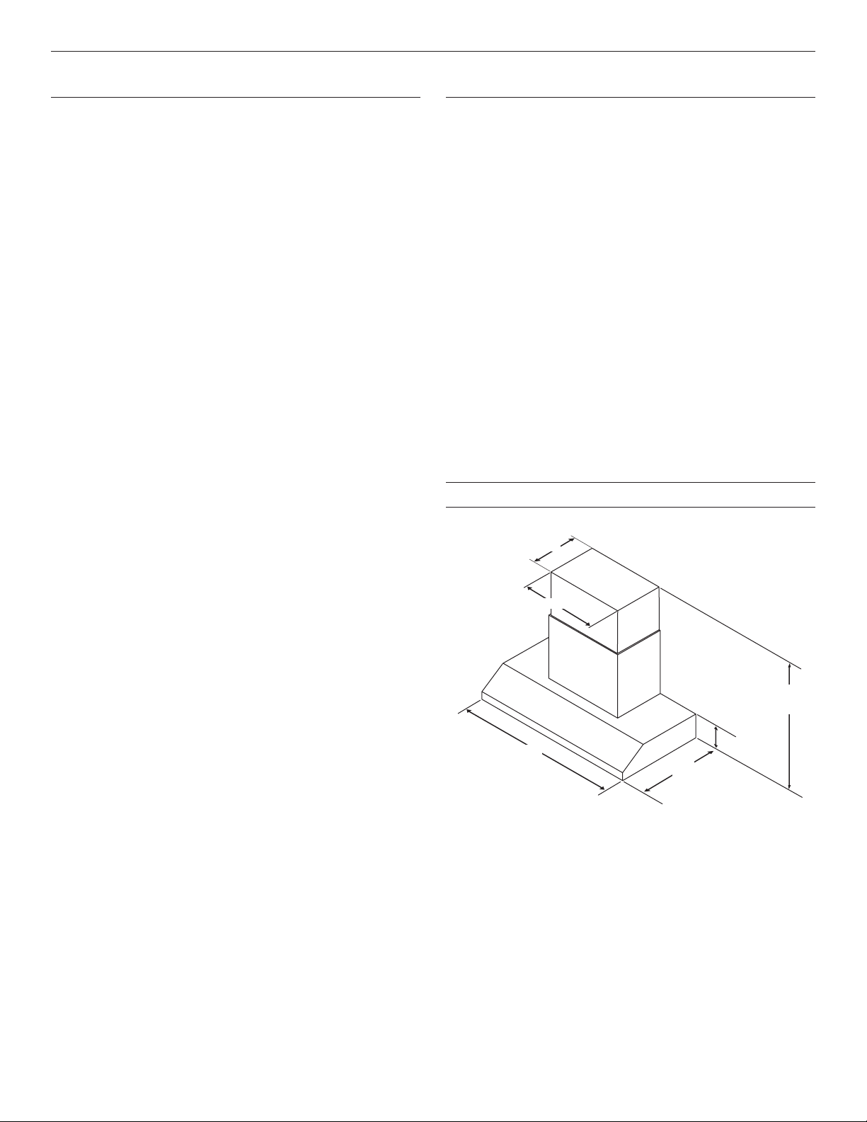
Product Dimensions
Vented Installations
11⁵⁄₁₆" (28.7 cm)
22³⁄₄" (57.8 cm)
32³⁄₈
50¹¹⁄₁₆
36" (91.4 cm)
or 48" (121.9 cm)
25" (63.5 cm)
7⁷⁄₈" (20.0 cm)
†TORX® and T20® are registered trademarks of Acument Intellectual Properties, LLC.
5
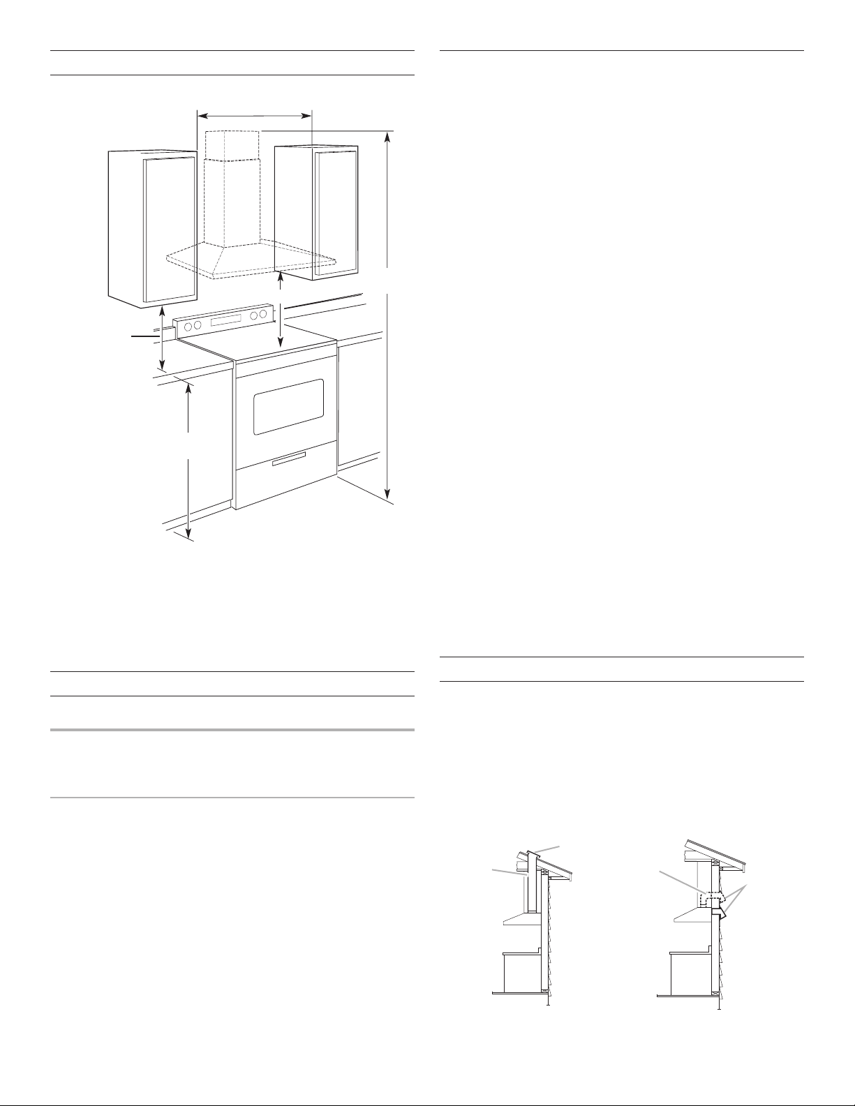
Installation Dimensions
18" (45.7 cm) min.
c
cabinet to counter
See Note*
36" (91.4 cm) or 48" (121.9 cm)
Roof Venting
Wall Venting
B
A
A
B.
round vent
learance upper
IMPORTANT:
Minimum distance “X”: 24" (61 cm) from electric cooking
surfaces
Minimum distance “X”: 30" (76.2 cm) from gas cooking
surfaces
The chimneys can be adjusted for different ceiling heights. See
the following chart.
Vented Installations
Electric cooking
surface
Gas cooking
surface
* NOTE: The range hood chimneys are adjustable and de-
signed to meet varying ceiling or soft heights depending on
the distance “X” between the bottom of the range hood and
the cooking surface. For higher ceilings, an Extension Kit Part
Number W10352733 is available from your dealer or an authorized parts distributor. The chimney extension replaces the
upper chimney shipped with the range hood.
or cabinet opening width
(if installed between cabinets)
X*
top
36" (91.4 cm)
countertop height
Min. ceiling height Max. ceiling height
7' 9" (2.36 m) 10' 2" (3.1 m)
8' 3" (2.51 m) 10' 2" (3.1 m)
Venting Requirements
■ Vent system must terminate to the outdoors.
■ Do not terminate the vent system in an attic or other
enclosed area.
■ Do not use 4" (10.2 cm) laundry-type wall caps.
■ Use metal vent only. Rigid metal vent is recommended.
Plastic or metal foil vent is not recommended.
■ The length of vent system and number of elbows should be
kept to a minimum to provide efcient performance.
For the most efficient and quiet operation:
■ Use no more than three 90° elbows.
■ Make sure there is a minimum of 24" (61.0 cm) of straight
vent between the elbows if more than one elbow is used.
■ Do not install two elbows together.
■ Use clamps to seal all joints in the vent system.
■ The vent system must have a damper. If the roof or wall
cap has a damper, do not use the damper supplied with the
range hood.
■ Use caulking to seal exterior wall or roof opening around
thecap.
■ The size of the vent should be uniform.
Cold weather installations
An additional back draft damper should be installed to minimize
backward cold air ow, and a thermal break should be installed
to minimize conduction of outside temperatures as part of the
vent system. The damper should be on the cold air side of the
thermal break.
The break should be as close as possible to where the vent
system enters the heated portion of the house.
Makeup air
Local building codes may require the use of makeup air systems
when using ventilation systems greater than specied CFM of air
movement. The specied CFM varies from locale to locale.
Consult your HVAC professional for specic requirements in
yourarea.
Venting Methods
Typical Internal Blower Motor System Venting Installations
A 10" (25.4 cm) round vent system is needed for installation
(notincluded). The range hood exhaust opening is 10" (25.4 cm)
round.
NOTE: Flexible vent is not recommended. Flexible vent
creates back pressure and air turbulence that greatly reduce
performance.
Vent system can terminate either through the roof or wall.
Tovent through the wall, a 90º elbow is needed.
A
B
. Roof cap
10" (25.4 cm)
round vent
6
A. Wall cap
B. 10" (25.4 cm)
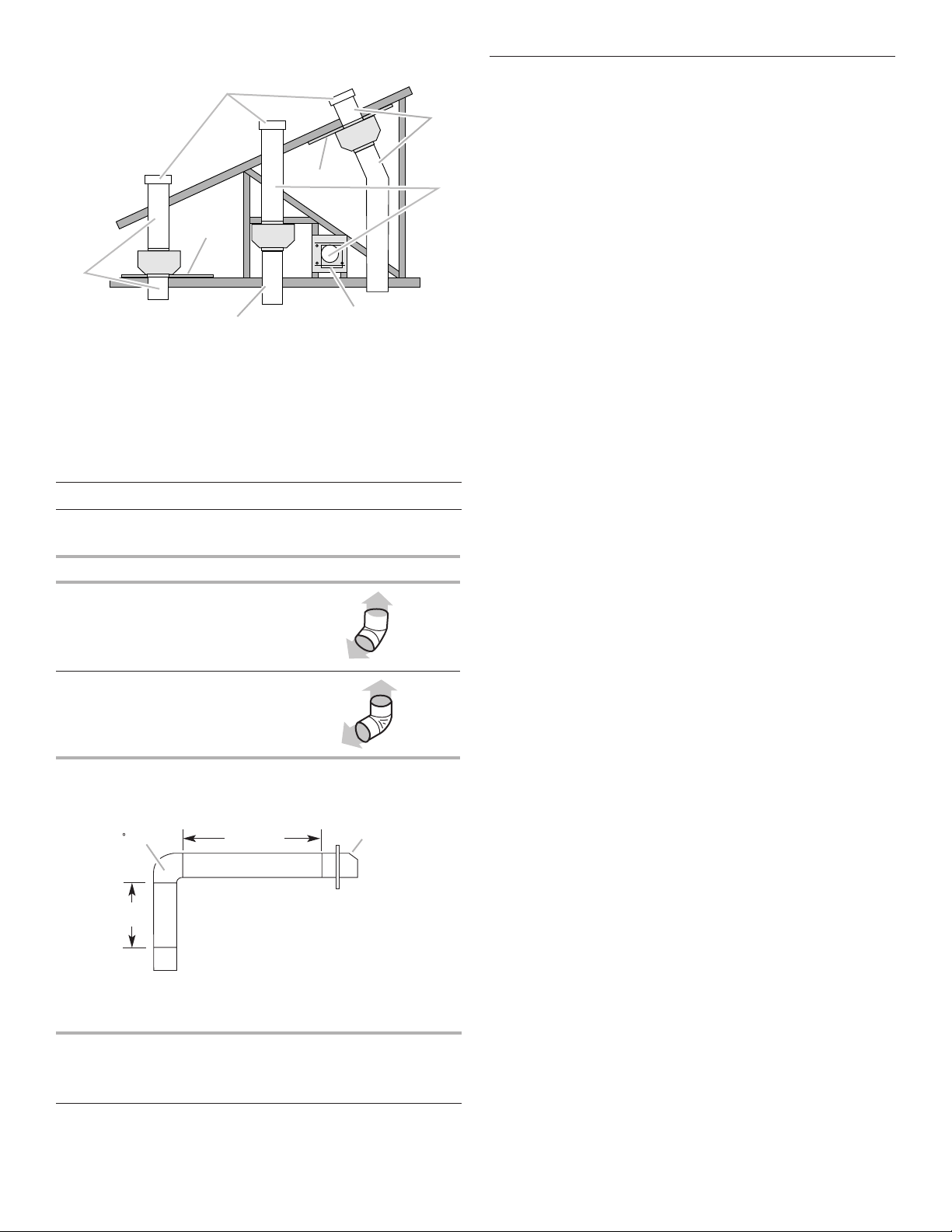
Typical In-line Blower Motor System Venting Installations
A
A
C
A
90 elbo
Wall cap
A
E
D
D
B
F
G
H
A. 10" (25.4 cm) round vent
B. Mount on top of ceiling joists
C. Roof caps
D. Plywood (optional on some installations)
E. Mount on underside of roof rafters
F. Mount from cross-members tied to trusses
G. Duct horizontal; mount to cross-members tied to trusses
H. Wall cap
Calculating Vent System Length
To calculate the length of the system you need, add the
equivalent feet (meters) for each vent piece used in the system.
Vent Piece Equivalent Length
45° elbow 2.5'
(0.8 m)
Electrical Requirements
Observe all governing codes and ordinances.
Ensure that the electrical installation is adequate and in
conformance with National Electrical Code, ANSI/NFPA 70
(latest edition), or CSA Standards C22.1-94, Canadian Electrical
Code, Part 1 and C22.2 No. 0-M91 (latest edition) and all local
codes and ordinances.
If codes permit and a separate ground wire is used, it is
recommended that a qualied electrician determine that the
ground path is adequate.
A copy of the above code standards can be obtained from:
National Fire Protection Association
One Batterymarch Park
Quincy, MA 02269
CSA International
8501 East Pleasant Valley Road
Cleveland, OH 44131-5575
■ A 120-volt, 60 Hz., AC-only, 15-amp, fused electrical circuit
is required.
■ If the house has aluminum wiring, follow the procedure
below:
Connect the aluminum wiring using special connectors
and/or tools designed and UL listed for joining copper to
aluminum.
Follow the electrical connector manufacturer’s recommended
procedure. Aluminum/copper connection must conform with
local codes and industry accepted wiring practices.
■ Wire sizes and connections must conform with the rating of
the appliance as specied on the model/serial rating plate.
The model/serial plate is located behind the lter on the rear
wall of the range hood.
■ Wire sizes must conform to the requirements of the National
Electrical Code, ANSI/NFPA 70 (latest edition), or CSA
Standards C22. 1-94, Canadian Electrical Code, Part 1 and
C22.2 No. 0-M91 (latest edition) and all local codes and
ordinances.
90° elbow 5.0'
(1.5 m)
The maximum equivalent vent lengths are:
10" (25.4 cm) round vent - 60" (18.3 m)
Example vent system
6 ft (1.8 m)
2 ft
(0.6 m)
w
The following example falls within the maximum recommended
vent length.
One 90° elbow = 5.0 ft (1.5 m)
One wall cap = 0.0 ft (0.0 m)
8 ft (2.4 m) straight = 8.0 ft (2.4 m)
Length of system = 13.0 ft (3.9 m)
7

INSTALLATION INSTRUCTIONS
A
" (43.5 cm)
B
C
"
(6.4 mm)
A
Prepare Location
■ It is recommended that the vent system be installed before
range hood is installed.
■ Before making cutouts, make sure there is proper clearance
within the ceiling or wall for exhaust vent.
■ Range hood is to be installed 24" (61.0 cm) minimum for
electric cooking surfaces, 30" (76.2 cm) minimum for gas
cooking surfaces, to a suggested maximum of 36" (91.4 cm)
above the cooking surface.
■ Check your ceiling height and the range hood height
maximum before you select your range hood.
1. Disconnect power.
2. Determine which venting method to use: roof or wall.
3. Select a at surface for assembling the range hood. Place
covering over that surface.
4. Drill 3/32" (2.4 mm) pilot holes for installation into wood.
The screws provided for mounting this range hood must be
fastened into solid wood. Do not fasten only into sheet rock.
IMPORTANT: All screws must be installed into wood. If there
is no wood to screw into, additional wall framing supports
may be required.
A
WARNING
Excessive Weight Hazard
Use two or more people to move and install in-line
blower motor system.
Failure to do so can result in back or other injury.
4. Using two or more people, lift range hood onto covered
surface.
Range Hood Mounting Screws Installation
1. Determine and mark the centerline on the wall where the
range hood will be installed.
2. Based on the ceiling or soft height, determine the distance
“X” (24" [61.0 cm] minimum from electric cooking surface or
30" [76.2 cm] minimum to gas cooking surface, suggested
36" [91.4 cm] maximum) needed between the cooking
surface and the bottom of the range hood. To this distance,
add 171/8" (43.5 cm) and draw a horizontal line (A) about
24"(61.0 cm) long centered on the vertical centerline (B) at
this distance.
D
B
C
X + 17¹⁄₈
A. Horizontal line
B. Vertical centerline of range hood
C. 511/16" (14.4 cm)
5. Install the 5 x 45 mm mounting screws. Leave a 1/4"
(6.4mm) gap between the wall and the back of the screw
head to slide range hood into place.
¹⁄₄
Chimney Support Bracket Installation
1. Place two of the chimney brackets against the wall so that
their top edges are 1/16" (2.0 mm) from the ceiling or soft
and level. Mark holes.
C
A. Vertical centerline
B. 1/16" (1.6 mm)
C. 109/16" (26.9 cm)
C
B
A. Horizontal line
B. Vertical centerline
C. Cooking surface
D. Distance “X” (24" [61.0 cm] min. from
electric cooking surface, 30" [76.2
cm] min. from gas cooking surface,
suggested 36" [91.4 cm] max.) +171/8"
(43.5 cm)
3. Following the illustrations in Step 4, mark points on each
side of the horizontal line as measured from the vertical
centerline.
8
2. Drill pilot holes.
■ If installing into wood, drill four 3/32" (2.4 mm) pilot
holes.
3. Attach each bracket to the wall with a 4.2 x 8 mm mounting
screw. Tighten screws securely.
Complete Preparation
A
A
A
A
1. Determine and make all necessary cuts in the wall for the
vent system. Install the vent system before installing the
range hood. See the “Venting Requirements” section.
2. Determine the location where the power supply cable will be
run through the wall. Be sure that the location will be covered
by the chimney of the range hood.
3. Drill a 11/4" (3.2 cm) hole at this location.
4. Pull enough power supply cable through the wall to allow for
easy connection to the terminal box.
5. Install the 10" (25.4 cm) square x 10" (25.4 cm) round
transition with damper to the top of range hood using the
three 4.2 x 8 mm screws.
NOTE: Your range hood requires you to purchase either
an internal type or an in-line (external type) blower motor
system.
For internal blower systems, there are blower motor
mounting parts in the blower motor installation packet that
must be added to the range hood prior to mounting the
range hood to the wall. See the “Install Range Hood Internal
Blower Motor” section and the instructions supplied with the
blower motor.
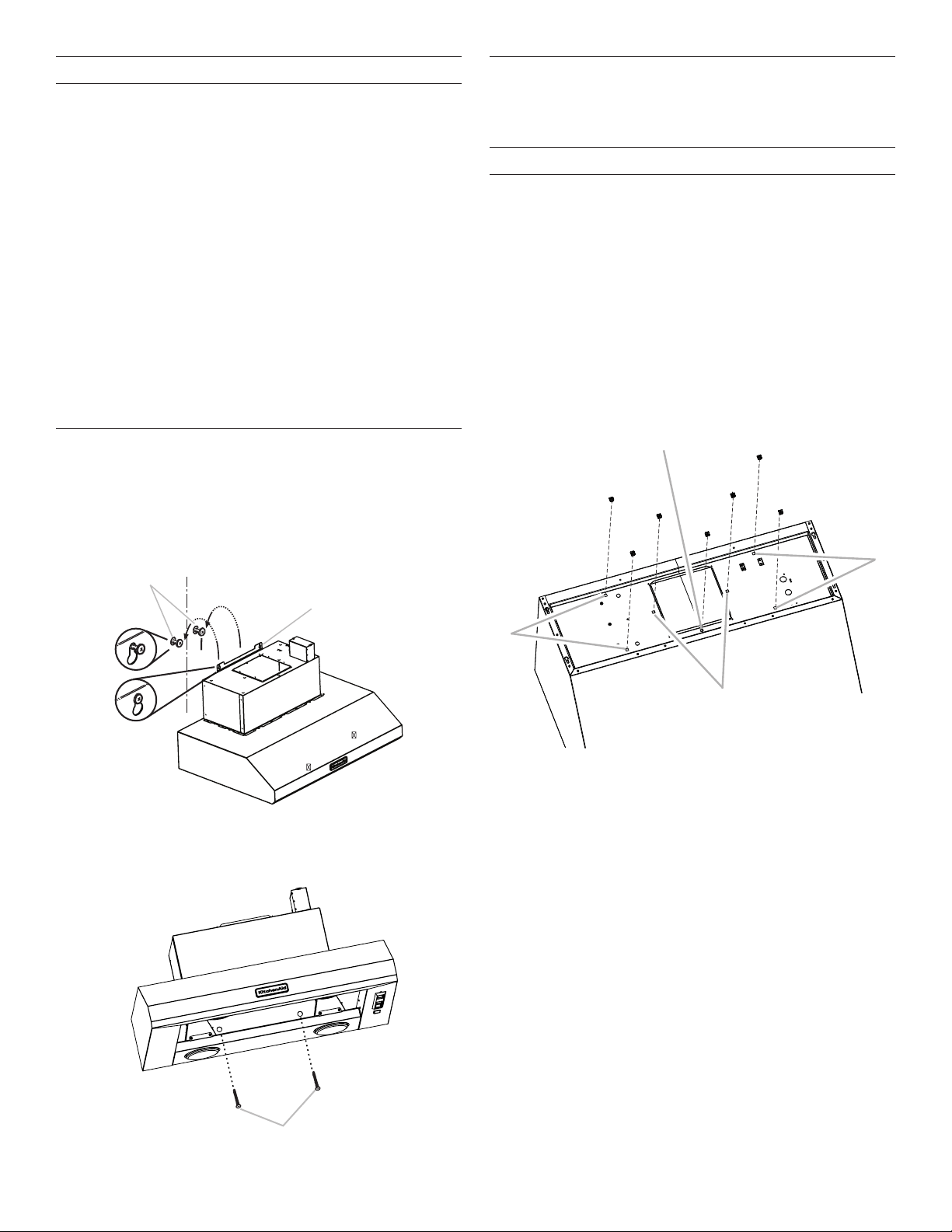
Install Range Hood
1. Remove the grease lter. See the “Range Hood Care”
section.
2. Using two or more people, hang range hood on two
mounting screws through the mounting slots on back of
range hood.Level the range hood and tighten upper
mounting screws.
Install Range Hood Internal Blower Motor
NOTE: Your range hood requires you to purchase either an
internal type or an in-line (external type) blower motor system.
See “Blower Motor System” in the “Accessories” section.
Prepare the Internal Blower System
IMPORTANT: Perform steps 1-4 before mounting the range
hood.
1. Remove grease lters from range hood. See the “Range
Hood Care” section.
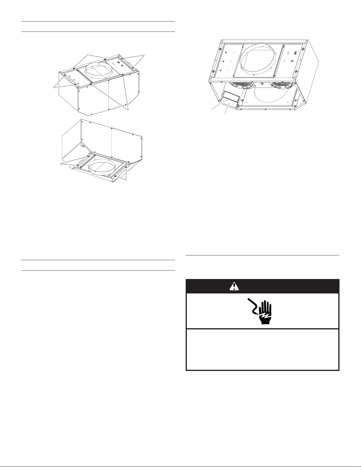
2. Install the 6 mm nuts to the outside top of the range hood at
the proper location for the selected motor system.
■ Two 6 mm nuts are required for the single motor system.
Clip the nuts into the small square notches located at the
left and right sides (centered) of the square to round vent
transition.
■ Five 6 mm nuts are required for the dual motor system.
Clip the nuts into the small square notches, one located
in the front of the square to round vent transition and the
other four located at the left and right ends of the square
to round vent transition.
A
B
A. Mounting screws
B. Mounting slots
3. Install two 5 x 45 mm lower-mounting screws and tighten.
B
A. Clip nut (6 mm) locations for dual motor assembly (quantity five)
B. Clip nut (6 mm) locations for single motor assembly (quantity two)
3. Disconnect the electrical connector to the heat lamp.
A. Lower-mounting screws
9

4. Using a T20® TORX® screwdriver, remove the ve or six
BA
A
A
A
A
screws holding the rear heat lamp panel, two in the sides
and three or four in the back. Set the heat lamp panel and
screws aside.
A
A. Screws: panel mounting (five) for 36" (91.4 cm)
models, (six) for 48" (121.9 cm) models
B. Panel: heat lamp
5. Mount range hood. See the “Install Range Hood” section.
Install Range Hood Internal Blower Motor
Dual Blower Motor Assembly
A. Wiring connection
2. Run the power supply wires and connector from the range
hood through the hole in the right end of the motor mounting
plate.
WARNING
Excessive Weight Hazard
Use two or more people to move and install
range hood.
Failure to do so can result in back or other injury.
1. Using two or more people, install the range hood blower
motor assembly inside the range hood canopy with the
wiring connection to the left for the single motor system and
to the front or top for the dual motor system.
Single Blower Motor Assembly
A. Wiring connection
B
A. Motor mounting plate hole
B. Power supply wires and connector
3. With the blower motor assembly mounting plate parallel
to the bottom of the range hood, slide it up into the cavity
above the range hood canopy.
4. Align mounting holes in motor mounting plate with motor
mounting clip nuts, and install 6 x 16 mm screws and
6.4mm lock washers (quantity two for single motor; quantity
ve for dual motor). After all the screws have been installed,
tighten the screws.
D
C
B
A. Screw with lock washer
B. Mounting hole in motor mounting plate
C. Clip nut (6 mm)
D. Motor mounting plate
10
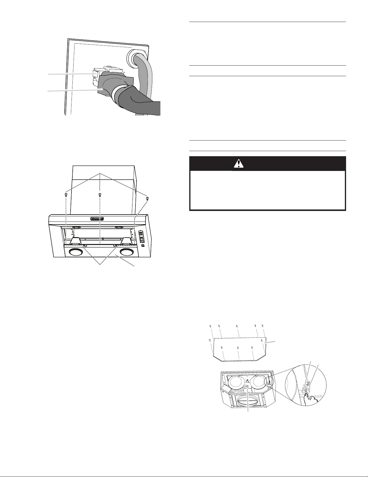
5. Attach power supply connector from the range hood to the
B
A
BA
D
connector on the blower motor assembly wiring box.
A. Blower motor assembly connector
B. Power supply connector from range hood
6. Reinstall the heat lamp panel using the screws removed in
the “Preparing the Internal Blower System,” two in the sides
and either three in the back for the 36" (91.4 cm) model or
four in the back for the 48" (121.9 cm) model.
A
Install Range Hood In-Line (External Type)
Blower Motor
NOTE: Your range hood requires you to purchase either an
internal type or an in-line (external type) blower motor system.
See “Blower Motor System” in the “Accessories” section.
Prepare for Mounting the In-Line Blower System
The in-line blower system must be fastened to a secure
structure of the roof, ceiling, wall, oor, or new or existing frame
construction. The four holes on either the inlet (bottom) side or
the outlet (top) side of the blower must be used to mount the inline blower system to the structure.
NOTE: The mounting hole locations must span the studs.
Additional stud framing may be required. Plywood may be used
to span open areas between ceiling joists or roof rafters to aid
installation. This structure must be strong enough to support the
weight of the in-line blower system (50 lb [22.6 kg] minimum).
Prepare the In-line Blower System
WARNING
Excessive Weight Hazard
Use two or more people to move and install in-line
blower motor system.
Failure to do so can result in back or other injury.
A. Screws: panel mounting (five) for 36" (91.4 cm)
models, (six) for 48" (121.9 cm) models
B. Panel: heat lamp
7. Reconnect the electrical connector to the heat lamp.
8. Go to the “Make Electric Power Supply Connection to Range
Hood” section.
1. Using two or more people, move the in-line blower motor
system to the mounting location.
2. Remove the 10 screws from the front cover of the in-line
blower motor housing and set them aside.
3. Remove the front cover of the in-line blower motor housing
and set it aside.
NOTE: To make the blower motor housing easier to mount,
the blower motor assembly can be removed. If you do not
want to remove the blower motor assembly, proceed to
“Install In-line Blower System” in this section.
4. Disconnect the motor electrical plug from the blower motor
assembly.
5. Remove the screws that secure the blower motor assembly
to the in-line blower housing and set them aside.
6. Pull the spring clip to release the blower motor assembly.
Remove the blower motor assembly from the housing and
place it on a covered surface.
A
B
C
A. Front cover
B. Blower mounting screws
C. Spring clip
D. Motor electrical plug
11
Install In-line Blower System
A
A
A
A
A
A
B
NOTE: The blower motor housing can be mounted using four
holes from either the inlet side or the outlet side of the blower.
Outlet Side
A
4. Locate the electrical terminal boxes in the in-line blower
housing and range hood. Remove the terminal box covers
and set the covers and screws aside.
Inlet Side
A. Mounting holes
1. Position the in-line blower motor housing in its mounting
location and mark the four mounting hole locations.
2. Drill four mounting pilot holes using a 3/16" (4.8 mm) drill bit.
3. Attach the in-line blower motor housing to the mounting
location with four 6 x 80 mm mounting screws and washers.
4. If it is removed, reinstall the blower motor assembly and
secure it with the screws previously removed.
5. If it is removed, reattach the motor electrical plug to the
connector on the blower motor assembly.
Complete Preparation
1. Determine and make all necessary cuts for the vent system.
IMPORTANT: When cutting or drilling into the ceiling or wall,
do not damage electrical wiring or other hidden utilities.
2. Determine the location where the 1/2" (13 mm) wiring
conduit will be routed through the ceiling or wall between the
in-line blower and the range hood.
3. Drill a 11/4" (3.2 cm) hole at this location.
A. Electrical terminal box
B. Electrical knockout
5. Remove the electrical knockout from the in-line blower
housing and range hood to prepare for the installation of the
UL Listed or CSA approved 1/2" (13 mm) wiring conduit and
conduit connector.
6. With the range hood mounted (see the “Install Range Hood”
section), run the 1/2" (13 mm) wiring conduit between the
inline blower motor housing and the range hood. Pull enough
1/2" (13 mm) wiring conduit to allow for easy connection to
the terminal boxes in the in-line blower housing and range
hood.
7. Run the six 18 AWG wires through the 1/2" (13 mm) wiring
conduit and conduit connectors and into the terminal
boxes on the in-line blower housing and range hood. Leave
enough wire length in each terminal box to make the wiring
connections.
8. Install the conduit connectors and conduit to the in-line
blower housing and range hood electrical terminal boxes.
9. Connect the vent system to the range hood and in-line
blower system and seal all joints with clamps.
Make Electrical Connections for In-Line
Blower Motor System
WARNING
Electrical Shock Hazard
Disconnect power before servicing.
Replace all parts and panels before operating.
Failure to do so can result in death or electrical shock.
Electrical Connection Inside In-line Blower System
1. Disconnect power.
12
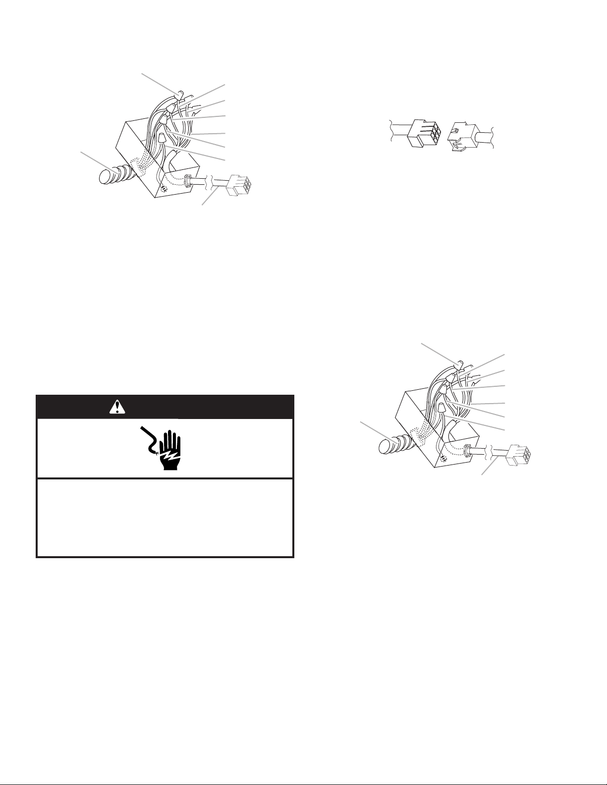
2. Connect the wires from the wiring conduit to the wires from
A
B
I
A
B
I
the motor electrical plug cable inside the in-line blower
housing terminal box.
C
D
E
F
G
H
A. UL Listed or CSA approved
1/2" (1.3 cm) wiring conduit
B. UL Listed wire connectors
C. Black wires
D. White wires
E. Red wires
F. Blue wires
G. Gray wires
H. Green (or yellow/green)
and green/yellow wires
I. Motor electrical plug cable
3. Use UL Listed wire connectors and connect the black wires
(C) together.
4. Use UL Listed wire connectors and connect the white wires
(D) together.
5. Use UL Listed wire connectors and connect the red wires (E)
together.
6. Use UL Listed wire connectors and connect the blue wires
(F) together.
7. Use UL Listed wire connectors and connect the gray wires
(G) together.
WARNING
Electrical Connection Inside Range Hood Between Inline Blower System and Range Hood
1. With the range hood mounted (see the “Install Range Hood”
section), locate the wiring cable connector inside the range
hood.
2. Connect the six-wire connector assembly supplied with the
in-line blower motor system to the mating cable connector
from the range hood.
3. Locate the terminal box inside the range hood and install a
1/2" (1.3 cm) UL Listed or CSA approved strain relief (see
“Complete Preparation” in the “Prepare Location” section).
4. Run the wire ends from the 6-wire connector assembly
through the 1/2" (1.3 cm) strain relief, leaving enough wire
length to make the wiring connections. Tighten the strain
relief screws.
5. Connect the wires from the six-wire connector assembly
to the wires from the wiring conduit inside the range hood
terminal box.
6. Connect the same color wires to each other (black to black,
white to white, etc.) using UL Listed wire connectors.
NOTE: Connect the green (or green/yellow) ground wire from
the wiring conduit to the green (or bare) ground wire from the
home power supply using UL listed wire connectors (see the
“Make Electrical Power Supply Connection to Range Hood”
section).
C
D
E
F
G
H
Electrical Shock Hazard
Electrically ground blower.
Connect ground wire to green and yellow ground wire
in terminal box.
Failure to do so can result in death or electrical shock.
A. UL Listed or CSA approved
1/2" (1.3 cm) wiring conduit
B. UL Listed wire connectors
C. Black wires
D. White wires
E. Red wires
F. Blue wires
G. Gray wires
H. Green (or yellow/green)
and green/yellow wires
I. Motor electrical plug cable
7. Go to “Make Electrical Power Supply Connection to Range
Hood” section.
8. Connect the green (or yellow/green) ground wire to the
green/yellow ground wire (H) in the terminal box using UL
Listed wire connectors.
9. Reinstall the in-line blower terminal box cover and screw.
10. Reinstall the front cover of the in-line blower housing and
secure it with 10 mounting screws.
13
Make Electrical Power Supply
A
C
D
E
Connection to Range Hood
WARNING
Electrical Shock Hazard
Disconnect power before servicing.
Replace all parts and panels before operating.
Failure to do so can result in death or electrical shock.
1. Disconnect power.
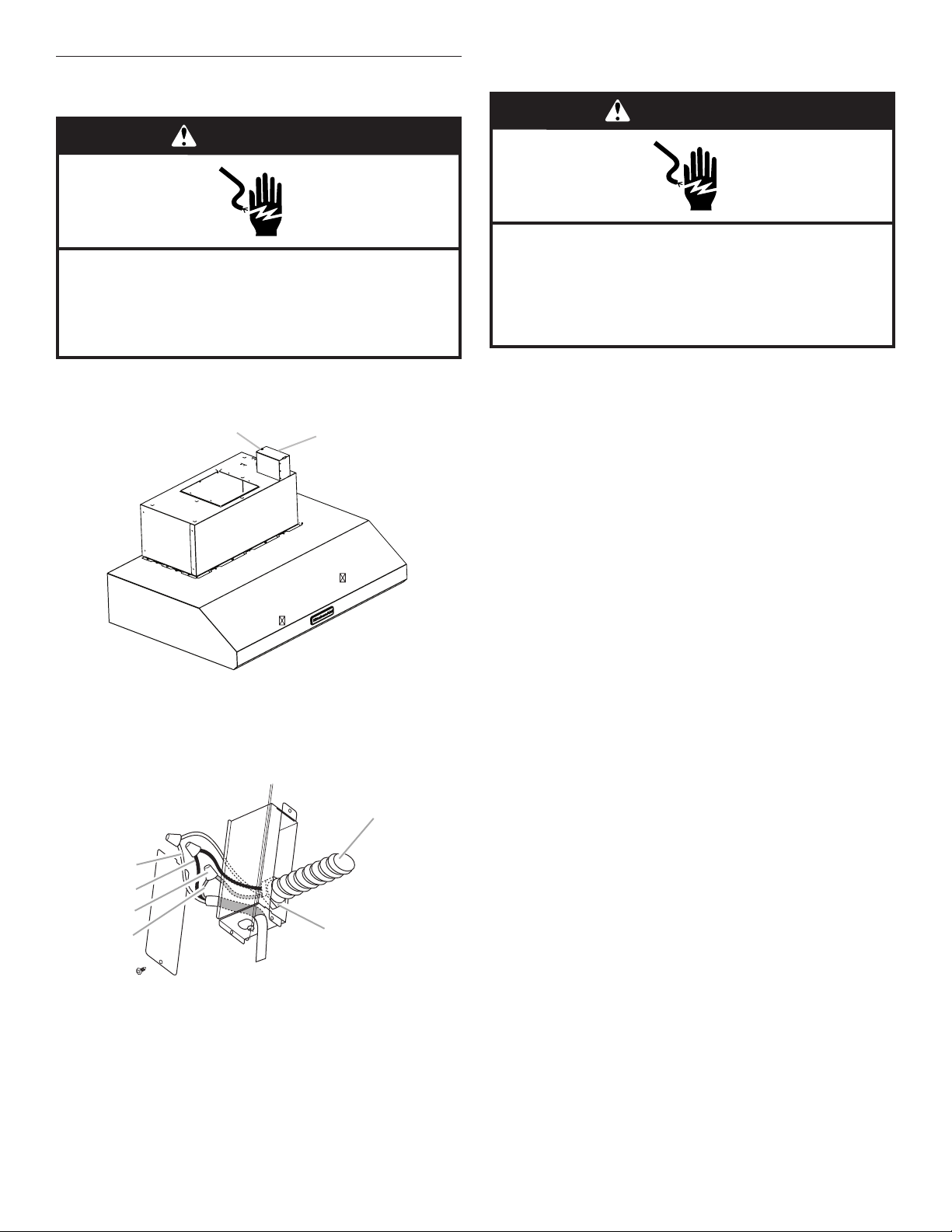
2. Locate terminal box on top of the range hood.
B
4. Use UL Listed wire connectors and connect white wires (A)
together.
WARNING
Electrical Shock Hazard
Electrically ground blower.
Connect ground wire to green and yellow ground wire
in terminal box.
Failure to do so can result in death or electrical shock.
NOTE: When using an in-line blower motor system, the green (or
green/yellow) ground wire in the conduit from the in-line blower
motor system is to be connected with the green (or bare) wire of
the home power supply cable and with the green/yellow wire (D)
in the terminal box.
5. Connect green (or bare) ground wire from home power
supply to the green/yellow ground wire (D) in terminal box
using UL Listed wire connectors.
6. Install terminal box cover.
7. Check that all light bulbs are secure in their sockets.
8. Reconnect power.
A. Knockout in back of terminal box
B. Top of terminal box
3. Use UL Listed wire connectors and connect black wires (B)
together.
A
B
A. White wires
B. Black wires
C. UL Listed wire connectors
D. Green, bare or yellow/green wires
E. Home power supply
F. UL Listed or CSA approved
1/2" (1.3 cm) strain relief
F
14
Install Chimney Covers
A
A
A
B
C
D
E
F
G
1. If it is not already installed, install damper on top of the
exhaust opening. Check that the damper opens freely.
2. Connect the vent system and seal all connections with
clamps.
Install Upper Chimney Cover
1. Slightly spread the sides of the cover apart and hook them
behind the chimney mounting brackets.
2. Attach the cover to the brackets with two at head screws.
3. Securely tighten screws.
A. Two flat head screws
Complete Installation and Check
Operation
1. Install grease lters. See the “Range Hood Care” section.
2. Check operation of the range hood blower and lights. See
the “Range Hood Use” section.
Install Lower Chimney Cover
1. Slightly spread the sides of the cover apart and hook them
behind the upper chimney.
2. Secure the lower chimney covers to the range hood canopy
using four 4.2 x 8 mm screws.
A. Lower chimney covers
B. Range hood canopy
C. Four 4.2 x 8 mm screws
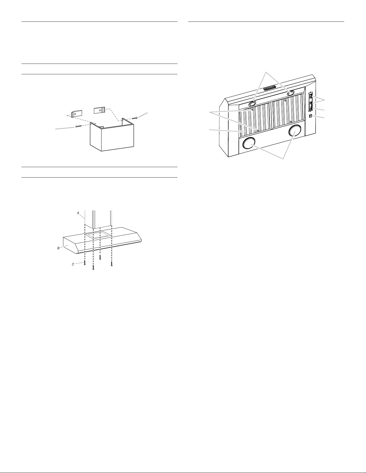
A. Halogen lights
B. Blower control switches
C. Halogen light switch
3. If range hood does not operate, check to see whether a
circuit breaker has tripped or a household fuse has blown.
Disconnect power supply and check that the wiring is
correct.
NOTE: To get the most efcient use from your new range
hood, read the “Range Hood Use” section.
D. Heat lamp switch
E. Heat lamps
F. Grease filter
G. Grease filter handles
15
RANGE HOOD USE
A
B
C
um
The range hood is designed to remove smoke, cooking vapors
and odors from the cooktop area. For best results, start the
range hood before cooking and allow it to operate several
minutes after the cooking is complete to clear all smoke and
odors from the kitchen.
The range hood controls are located on the underside of the
range hood.
Operating the Heat Lamp
The heat lamps are designed to keep food warm prior to serving.
The cooktop surface is too far away from the heat lamp to be
used as a shelf.
For best results, install a metal shelf to hold the food closer to
the lamps. The optimum distance between the shelf and the
range hood is 12" (30.5 cm) to 15" (38.1 cm).
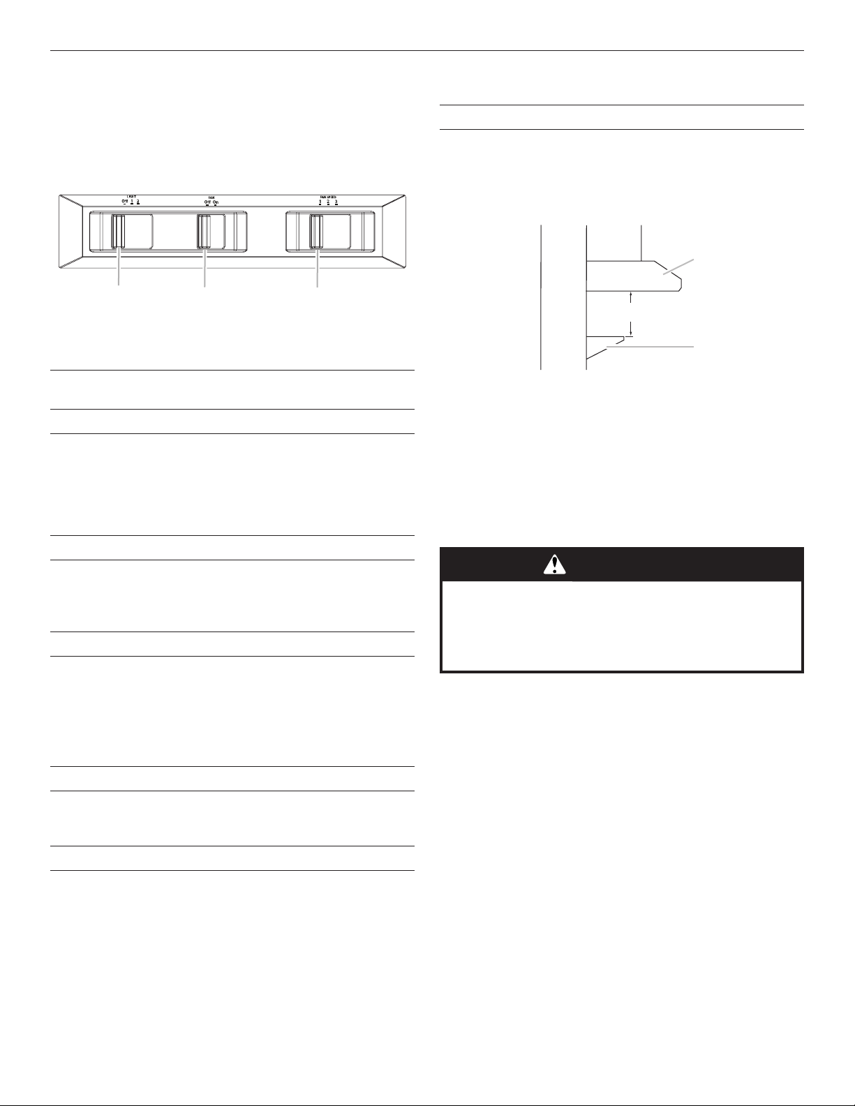
A
A. Light control
B. Blower control
C. Fan speed control
Range Hood Controls
Operating the Light
1. Move the light switch to the “1” position to turn range hood
light to night light setting.
2. Move the light switch to the “2” position to turn range hood
light to full light setting.
3. Move the light switch to the “Off” position to turn range hood
light off.
Operating the Fan
1. Move the fan switch to the “On” position to turn the fan
on. The fan will begin operating at the speed set on the fan
speed switch.
2. Move the fan switch to the “Off” position to turn the fan off.
Auto On Fan
The range hood is equipped with a sensor to automatically
turn on the fan when excessive heat is detected in the control
area. When the fan switch is in the “Off” position, this sensor
will turn the fan to high speed when necessary. When the heat
decreases, the fan will turn off.
When the fan switch is in the “On” position, the heat sensor is
not active and the range hood functions normally.
12" (30.5 cm) Minimum
15" (38.1 cm) Maxim
B
A. Range hood
B. Metal shelf
For best performance, food should be placed directly under the
heat lamps, not between them. You may need to adjust your
food placement to match your needs.
1. Install heat lamp bulbs into heat lamp sockets.
NOTE: Heat lamp bulbs should be rated to a maximum of
175 watts each. For best performance, 175-watt maximum,
PAR38 type, red heat lamp bulbs are recommended. Bulb
performance varies. Lower wattage and clear bulbs decrease
the performance.
WARNING
Food Poisoning Hazard
Do not let food sit for more than one hour before or
after cooking.
Doing so can result in food poisoning or sickness.
2. To turn on the heat lamps, move the switch to the “I”
position. To turn off the heat lamps, move the switch to the
“O” position.
Adjusting the Fan
The fan has three speed controls. Move the fan speed switch to
“1” position for low speed, “2” position for medium speed, or “3”
position for high speed.
Thermal Protector
The range hood is equipped with a thermal protector to avoid
overheating conditions. If the range hood shuts off while in use,
move fan slider switch to “Off” to turn off the range hood. Wait
approximately 60 minutes, then move slider to “On” to restart
the range hood.
16
RANGE HOOD CARE
Cleaning
IMPORTANT: Clean the range hood and grease lters frequently
according to the following instructions. Replace grease lters
before operating range hood.
Exterior Surfaces:
To avoid damage to the exterior surface, do not use steel wool
or soap-lled scouring pads.
Always wipe dry to avoid water marks.
Cleaning Method:
■ Liquid detergent soap and water or all-purpose cleanser.
■ Wipe with damp soft cloth or nonabrasive sponge, then rinse
with clean water and wipe dry.
Metal Grease Filter
Replacing a Heat Lamp
This range hood uses two 175-watt maximum heat lamps. Turn
off the heat lamps and allow them to cool.
To Replace:
1. Disconnect power.
2. Remove the heat lamp bulb from its socket.
3. Replace the heat lamp bulb with the same type bulb and
tighten it in its socket.
4. Repeat steps 2 and 3 with the other heat lamp bulb if
necessary.
5. Reconnect the power.
To Remove Metal Grease Filters:
1. Use two hands to remove the metal grease lters. Grasp
lter handles, push toward the rear of the range hood and
pull down on the front handle to remove.
2. Repeat for each grease lter.
3. Wash metal grease lters as needed in a dishwasher or hand
wash in a hot detergent solution to clean.
To Reinstall Metal Grease Filters:
1. Grasp lter handles and place rear of lter into rear track.
2. Push down on the rear handle and set the front of the grease
lter into the front track to secure.
3. Repeat for each lter.
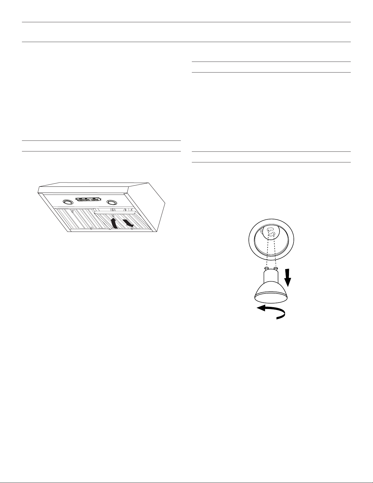
Replacing a Halogen Lamp
Turn off the range hood and allow the halogen lamp to cool.
To avoid damage or decreasing the life of the new bulb, do
not touch bulb with bare ngers. Replace bulb, using tissue or
wearing cotton gloves to handle bulb.
If new lamps do not operate, make sure the lamps are inserted
correctly before calling service.
1. Disconnect power.
2. Push up on the lens and turn it counterclockwise.
3. Remove the bulb and replace it with a 120-volt, 50-watt
maximum halogen bulb with a GU10 base. Turn it clockwise
to lock it into place.
4. Repeat steps 2-3 for the other bulb if needed.
5. Reconnect power.
17
 Loading...