

KitchenAid KXW9736Y, KXW9748Y Installation Guide
36" (91.4 CM) AND 48" (121.9CM) DESIGNER
COMMERCIAL-STYLE WALL-MOUNT CANOPY
RANGE HOOD
Installation Instructions and Use & Care Guide
For questions about features, operation/performance, parts, accessories or service, call: 1-800-422-1230
In Canada, for assistance, installation and service, call: 1-800-807-6777
or visit our website at www.kitchenaid.com
or visit our website at www.kitchenaid.ca
HOTTE DE CUISINIÈRE STYLISÉE DE TYPE
COMMERCIAL, À MONTAGE MURAL -
36" (91,4 CM) ET 48" (121,9 CM)
Instructions d’installation et Guide d’utilisation et d’entretien
Au Canada, pour assistance, installation ou service composez le 1-800-807-6777
Para obtener acceso al manual de uso y cuidado en español, o para obtener información adicional acerca de su producto, visite:
Tenga listo su número de modelo completo. Puede encontrar el número de modelo y de serie dentro de la cavidad superior de la puerta.
ou visitez notre site web à www.kitchenaid.ca
www.kitchenaid.com.
Table of Contents/Table des matières.............................................................................2
IMPORTANT: READ AND SAVE THESE INSTRUCTIONS.
FOR RESIDENTIAL USE ONLY.
IMPORTANT : LIRE ET CONSERVER CES INSTRUCTIONS.
POUR UTILISATION RÉSIDENTIELLE UNIQUEMENT.
LI3ZBB/W11374535A
TABLE OF CONTENTS
TABLE DES MATIÈRES
RANGE HOOD SAFETY .................................................................2
INSTALLATION REQUIREMENTS................................................4
Tools and Parts............................................................................4
Location Requirements................................................................4
Venting Requirements..................................................................5
Electrical Requirements ...............................................................6
INSTALLATION INSTRUCTIONS..................................................7
Prepare Location..........................................................................7
Install Range Hood.......................................................................8
Install Range Hood Internal Blower Motor...................................8
Install Range Hood In-Line (External Type) Blower Motor ........10
Make Electrical Connections for In-Line Blower
Motor System..................................................................
Make Electrical Power Supply Connection to Range Hood .....13
Install Chimney Covers ..............................................................14
Complete Installation and Check Operation..............................14
RANGE HOOD USE......................................................................15
Range Hood Controls ................................................................15
RANGE HOOD CARE ...................................................................16
Cleaning......................................................................................16
WIRING DIAGRAM .......................................................................17
ASSISTANCE OR SERVICE.........................................................18
In the U.S.A. ...............................................................................18
In Canada ...................................................................................18
Accessories ................................................................................18
...........12
SÉCURITÉ DE LA HOTTE DE CUISINIÈRE ...............................21
EXIGENCES D'INSTALLATION ...................................................23
Outils et pièces...........................................................................23
Exigences d'emplacement.........................................................23
Exigences concernant l'évacuation ...........................................24
Spécifications électriques..........................................................26
INSTRUCTIONS D'INSTALLATION.............................................26
Préparation de l'emplacement...................................................26
Installation de la hotte................................................................27
Installation du moteur du ventilateur interne de la hotte...........28
Installation du moteur du ventilateur en ligne (externe) de
la hotte................
Réalisation des connexions électriques du système du
moteur du ventilateur en ligne....................................................32
Réalisations des connexions de l’alimentation
électrique à la hotte....................................................................33
Installation du cache-cheminée .................................................34
Achever l'installation et vérifier le fonctionnement ....................34
UTILISATION DE LA HOTTE .......................................................35
Commandes de la hotte de cuisinière .......................................35
ENTRETIEN DE LA HOTTE..........................................................36
Nettoyage ...................................................................................36
SCHÉMA DE CÂBLAGE...........................................
ASSISTANCE OU SERVICE.........................................................38
Au Canada..................................................................................38
Accessoires ................................................................................38
........................................................................30
....................37
RANGE HOOD SAFETY
Your safety and the safety of others are very important.
We have provided many important safety messages in this manual and on your appliance. Always read and obey all safety
messages.
This is the safety alert symbol.
This symbol alerts you to potential hazards that can kill or hurt you and others.
All safety messages will follow the safety alert symbol and either the word “DANGER” or “WARNING.”
These words mean:
You can be killed or seriously injured if you don't immediately
DANGER
WARNING
All safety messages will tell you what the potential hazard is, tell you how to reduce the chance of injury, and tell you what can
happen if the instructions are not followed.
follow instructions.
You
can be killed or seriously injured if you don't
instructions.
follow
2

IMPORTANT SAFETY INSTRUCTIONS
WARNING: TO REDUCE THE RISK OF FIRE, ELECTRIC
SHOCK, OR INJURY TO PERSONS, OBSERVE THE
FOLLOWING:
■ Use this unit only in the manner intended by the
manufacturer. If you have questions, contact the
manufacturer.
■ Before servicing or cleaning the unit, switch power off at
service panel and lock the service disconnecting means to
prevent power from being switched on accidentally. When
the service disconnecting means cannot be locked,
securely fasten a prominent warning device, such as a tag,
to the service panel.
■ Installation work and electrical wiring must be done by
qualified person(s) in accordance with all applicable codes
and standards, including fire-rated construction.
■ Do not operate any fan with a damaged cord or plug.
Discard fan or return to an authorized service facility for
examination and/or repair.
■ Sufficient air is needed for proper combustion and
exhausting of gases through the flue (chimney) of fuel
burning equipment to prevent backdrafting. Follow the
heating equipment manufacturer's guideline and safety
standards such as those published by the National Fire
Protection Association (NFPA), the American Society for
Heating, Refrigeration and Air Conditioning Engineers
(ASHRAE), and the local code authorities.
■ When cutting or drilling into wall or ceiling; do not damage
electrical wiring and other utilities.
■ Ducted fans must always be vented outdoors.
CAUTION: For general ventilating use only. Do not use
to exhaust hazardous or explosive materials and vapors.
CAUTION: To reduce risk of fire and to properly exhaust
air, be sure to duct air outside - do not vent exhaust air into
spaces within walls or ceilings, attics or into crawl spaces,
or garages.
WARNING: TO REDUCE THE RISK OF FIRE, USE ONLY
METAL DUCTWORK.
WARNING: TO REDUCE THE RISK OF A RANGE TOP
GREASE FIRE:
■ Never leave surface units unattended at high settings.
Boilovers cause smoking and greasy spillovers that may
ignite. Heat oils slowly on low or medium settings.
■ Always turn hood ON when cooking at high heat or when
flambeing food (i.e. Crepes Suzette, Cherries Jubilee,
Peppercorn Beef Flambé).
■ Clean ventilating fans frequently. Grease should not be
allowed to accumulate on fan or filter.
■ Use proper pan size. Always use cookware appropriate for
the size of the surface element.
WARNING: TO REDUCE THE RISK OF INJURY TO
PERSONS IN THE EVENT OF A RANGE TOP GREASE
FIRE, OBSERVE THE FOLLOWING:
■ SMOTHER FLAMES with a close fitting lid, cookie sheet, or
metal tray, then turn off the burner. BE CAREFUL TO
PREVENT BURNS. If the flames do not go out
immediately, EVACUATE AND CALL THE FIRE
DEPARTMENT.
■ NEVER PICK UP A FLAMING PAN - you may be burned.
■ DO NOT USE WATER, including wet dishcloths or towels -
a violent steam explosion will result.
■ Use an extinguisher ONLY if:
– You know you have a class ABC extinguisher, and you
already know how to operate it.
– The fire is small and contained in the area where it
started.
– The fire department is being called.
– You can fight the fire with your back to an exit.
a
Based on "Kitchen Fire Safety Tips" published by NFPA.
■ WARNING: To reduce the risk of fire or electrical shock,
do not use this fan with any solid-state speed control
device.
a
READ AND SAVE THESE INSTRUCTIONS
3
INSTALLATION REQUIREMENTS
Tools and Parts
Gather the required tools and parts before starting installation.
Read and follow the instructions provided with any tools listed
here.
Too ls n ee ded
■ Level
■ Drill
■ Drill 1¼" (3 cm) drill bit
■ ³⁄₃₂" (2.4 mm) drill bit if installing into wood
■ Pencil
■ Wire stripper or utility knife
■ Tape measure or ruler
■ Pliers
■ Caulking gun and weatherproof caulking compound
■ Vent clamps
■ Jigsaw or keyhole saw
■ Flat-blade screwdriver
■ Metal snips
■ Phillips screwdriver
■ Scissors
Parts needed
■ Home power supply cable
■ 1 - ½" (12.7 mm) UL listed or CSA approved strain relief
■ 3 UL listed wire connectors
■ 1 wall or roof cap
■ Metal vent system
■ 2 - 175-watt max heat lamp bulbs
■ Blower motor system - internal or external (see “Blower
Motor System” in the “Accessories” section.)
Parts supplied
Remove parts from packages. Check that all parts are included.
■ 2 metal grease filters for 36" (91.4 cm) models
3 metal grease filters for 48" (121.9 cm) models
■ Damper
■ 2 - Vent cover support brackets
■ 2 - 10 x 50 mm mounting screws
■ 2 - 8 x 40 mm mounting screws
■ 2 - D5.3 x 20 mm washers
■ 4 - 5 x 45 mm screws
■ 6 - 4.2 x 8 mm screws
■ T-20 TORX
®†
adapter
Location Requirements
IMPORTANT: Observe all governing codes and ordinances.
Have a qualified technician install the range hood. It is the
installer's responsibility to comply with installation clearances
specified on the model/serial rating plate. The model/serial rating
plate is located inside the range hood on the rear wall of the
range hood.
Canopy range hood location should be away from strong draft
areas, such as windows, doors and strong heating vents.
Cabinet opening dimensions that are shown must be used. Given
dimensions provide minimum clearance.
The canopy range hood is factory set for venting through the roof
or through the wall.
All openings in ceiling and wall where canopy range hood will be
installed must be sealed.
For Mobile Home Installations
The installation of this range hood must conform to the
Manufactured Home Construction Safety Standards, Title 24
CFR, Part 328 (formerly the Federal Standard for Mobile Home
Construction and Safety, Title 24, HUD, Part 280) or when such
standard is not applicable, the standard for Manufactured Home
Installation 1982 (Manufactured Home Sites, Communities and
Setups) ANSI A225.1/NFPA 501A, or latest edition, or with local
codes.
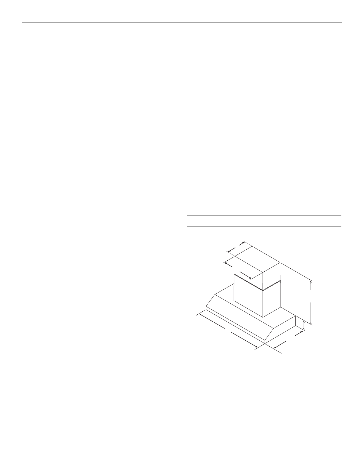
Product Dimensions
Vented Installations
11⁵⁄₁₆" (28.7 cm)
22³⁄₄" (57.8 cm)
24½" (62.3 cm) min.
32⁷⁄₁₆" (82.4 cm) max.
36" (91.4 cm)
or 48" (121.9 cm)
25" (63.5 cm)
7⁷⁄₈" (20.0 cm)
†®TORX is a registered trademark of Saturn Fasteners, Inc.
4
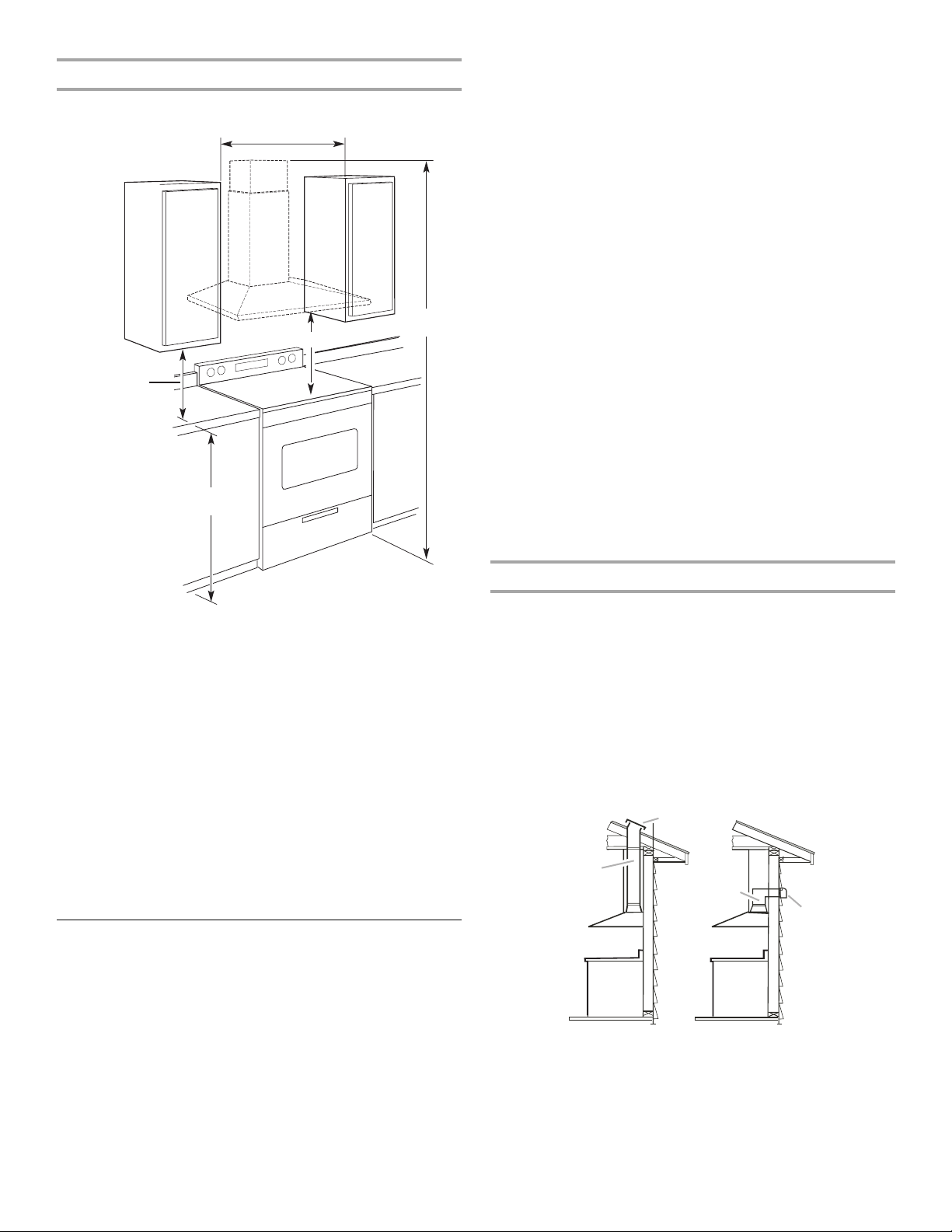
Installation Dimensions
36" (91.4 cm) or 48" (121.9 cm)
or cabinet opening width
(if installed between cabinets)
For the most efficient and quiet operation:
■ Use no more than three 90° elbows.
■ Make sure there is a minimum of 24" (61.0 cm) of straight
vent between the elbows if more than 1 elbow is used.
■ Do not install 2 elbows together.
■ Use clamps to seal all joints in the vent system.
■ The vent system must have a damper. If the roof or wall cap
has a damper, do not use the damper supplied with the range
hood.
■ Use caulking to seal exterior wall or roof opening around the
cap.
■ The size of the vent should be uniform.
See Note*
X*
18" (45.7 cm) min.
clearance upper
cabinet to countertop
36" (91.4 cm)
countertop height
*NOTE: The range hood chimneys are adjustable and designed
to meet varying ceiling or soffit heights depending on the
distance “X” between the bottom of the range hood and the
cooking surface. For higher ceilings, an Extension Kit Part
Number W10352733 is available from your dealer or an
authorized parts distributor. The chimney extension replaces the
upper chimney shipped with the range hood.
IMPORTANT:
Minimum distance “X”: 24" (61 cm) from electric cooking
surfaces
Minimum distance “X”: 30" (76.2 cm) from gas cooking
surfaces
The chimneys can be adjusted for ceilings between 8' 2³⁄₈" (2.5 m)
and 8' 10⁵⁄₁₆" (2.7 m) when mounted at 30" (76.2 cm) height over
a gas cooking surface.
The chimneys can be adjusted for ceilings between 7' 8³⁄₈" (2.4 m)
and 8' 4⁵⁄₁₆" (2.55 m) when mounted at 24" (61 cm) height over
electric cooking surface.
Cold weather installations
An additional back draft damper should be installed to minimize
backward cold air flow and a thermal break should be installed to
minimize conduction of outside temperatures as part of the vent
system. The damper should be on the cold air side of the thermal
break.
The break should be as close as possible to where the vent
system enters the heated portion of the house.
Makeup air
Local building codes may require the use of makeup air systems
when using ventilation systems greater than specified CFM of air
movement. The specified CFM varies from locale to locale.
Consult your HVAC professional for specific requirements in your
area.
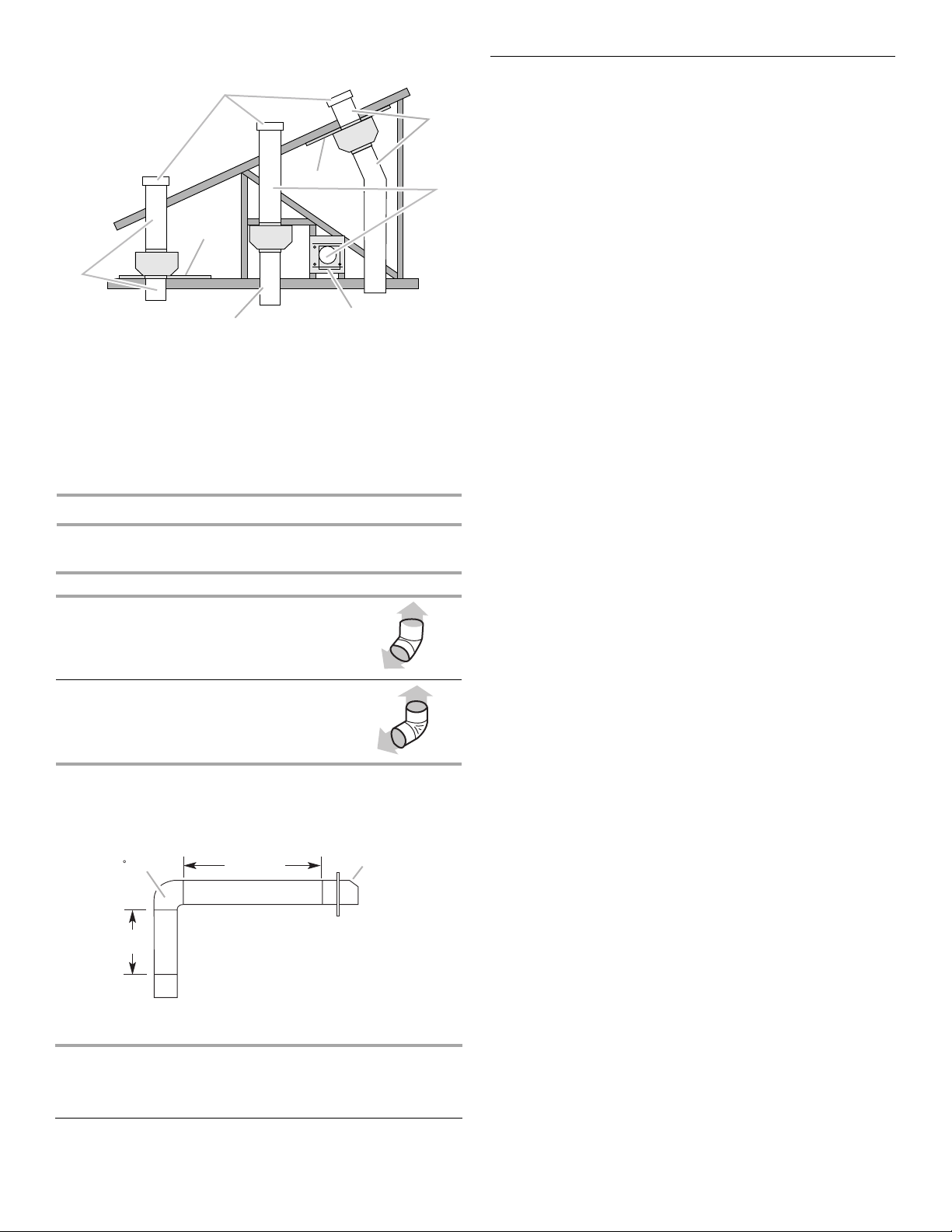
Venting Methods
Typical Internal Blower Motor System Venting Installations
A 10" (25.4 cm) round vent system is needed for installation (not
included). The range hood exhaust opening is 10" (25.4 cm)
round.
NOTE: Flexible vent is not recommended. Flexible vent creates
back pressure and air turbulence that greatly reduce
performance.
Vent system can terminate either through the roof or wall. To vent
through the wall, a 90º elbow is needed.
Roof Venting Wall Venting
A
B
B
A
Venting Requirements
■ Vent system must terminate to the outdoors.
■ Do not terminate the vent system in an attic or other enclosed
area.
■ Do not use 4" (10.2 cm) laundry-type wall caps.
■ Use metal vent only. Rigid metal vent is recommended.
Plastic or metal foil vent is not recommended.
■ The length of vent system and number of elbows should be
kept to a minimum to provide efficient performance.
A. Roof cap
B. 10" (25.4 cm)
round vent
A. Wall cap
B. 10" (25.4 cm)
round vent
5
Typical In-line Blower Motor System Venting Installations
A
C
A
E
D
D
A
B
A. 10" (25.4 cm) round vent
B. Mount on top of ceiling joists.
C. Roof caps
D. Plywood (optional on some installations)
E. Mount on underside of roof rafters.
F. Mount from cross-members tied to trusses.
G. Duct horizontal; mount to cross-members
tied to trusses.
H. Wall cap
F
A
G
H
Calculating Vent System Length
To calculate the length of the system you need, add the
equivalent feet (meters) for each vent piece used in the system.
Vent Piece Equivalent Length
45° elbow 2.5 ft
90° elbow 5.0 ft
(0.8 m)
(1.5 m)
Electrical Requirements
Observe all governing codes and ordinances.
Ensure that the electrical installation is adequate and in
conformance with National Electrical Code, ANSI/NFPA 70 (latest
edition), or CSA Standards C22.1-94, Canadian Electrical Code,
Part 1 and C22.2 No. 0-M91 (latest edition) and all local codes
and ordinances.
If codes permit and a separate ground wire is used, it is
recommended that a qualified electrician determine that the
ground path is adequate.
A copy of the above code standards can be obtained from:
National Fire Protection Association
One Batterymarch Park
Quincy, MA 02269
CSA International
8501 East Pleasant Valley Road
Cleveland, OH 44131-5575
■ A 120 volt, 60 Hz., AC only, 15-amp, fused electrical circuit is
required.
■ If the house has aluminum wiring, follow the procedure
below:
1. Connect a section of solid copper wire to the pigtail
leads.
2. Connect the aluminum wiring to the added section of
copper wire using special connectors and/or tools
designed and UL listed for joining copper to aluminum.
Follow the electrical connector manufacturer's recommended
procedure. Aluminum/copper connection must conform with
local codes and industry accepted wiring practices.
■ Wire sizes and connections must conform with the rating of
the appliance as specified on the model/serial rating plate.
The model/serial plate is located behind the filter on the rear
wall of the range hood.
■ Wire sizes must conform to the requirements of the National
Electrical Code, ANSI/NFPA 70 (latest edition), or CSA
Standards C22. 1-94, Canadian Electrical Code, Part 1 and
C22.2 No. 0-M91 (latest edition) and all local codes and
ordinances.
The maximum equivalent vent lengths are:
10" (25.4 cm) round vent - 60 ft (18.3 m)
Example vent system
90 elbow
2 ft
(0.6 m)
6 ft (1.8 m)
The following example falls within the maximum recommended
vent length.
1 - 90° elbow = 5.0 ft (1.5 m)
1 - wall cap = 0.0 ft (0.0 m)
8 ft (2.4 m) straight = 8.0 ft (2.4 m)
Length of system = 13.0 ft (3.9 m)
Wall cap
6
INSTALLATION INSTRUCTIONS
Prepare Location
■ It is recommended that the vent system be installed before
range hood is installed.
■ Before making cutouts, make sure there is proper clearance
within the ceiling or wall for exhaust vent.
■ Range hood is to be installed 24" (61.0 cm) min. for electric
cooking surfaces, 30" (76.2 cm) min. for gas cooking
surfaces, to a suggested maximum of 36" (91.4 cm) above
the cooking surface.
■ Check your ceiling height and the range hood height
maximum before you select your range hood.
1. Disconnect power.
2. Determine which venting method to use: roof or wall.
3. Select a flat surface for assembling the range hood. Place
covering over that surface.
WARNING
Excessive Weight Hazard
Use two or more people to move and install
range hood.
Failure to do so can result in back or other injury.
4. Drill ³⁄₃₂" (2.4 mm) pilot holes for installation into wood. The
screws provided for mounting this range hood must be
fastened into solid wood. Do not fasten only into sheet rock.
IMPORTANT: All screws must be installed into wood. If there
is no wood to screw into, additional wall framing supports
may be required.
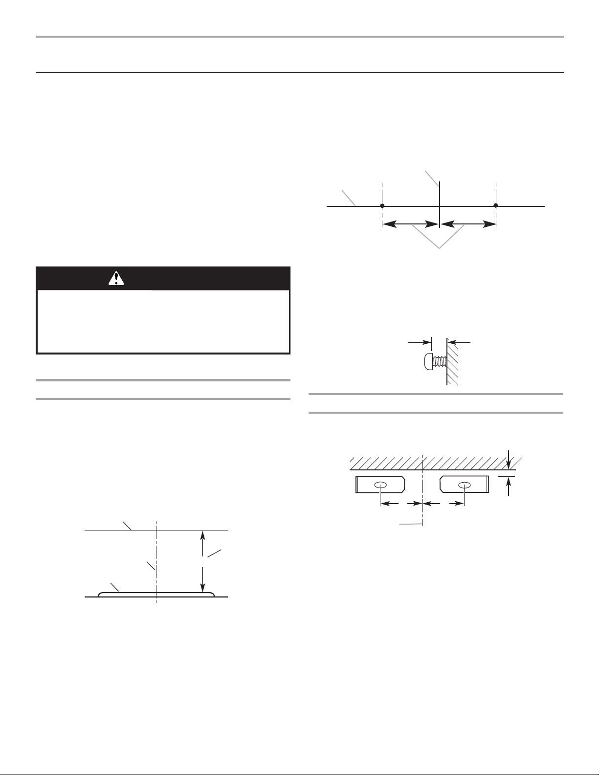
B
A
C
A. Horizontal line
B. Vertical centerline of range hood
C. 5¹¹⁄₁₆" (14.4 cm)
5. Install the 4.2 x 9.5 cm mounting screws. Leave a
¹⁄₄" (6.4 mm) gap between the wall and the back of the screw
head to slide range hood into place.
¹⁄₄"
(6.4 mm)
4. Using 2 or more people, lift range hood onto covered surface.
Range Hood Mounting Screws Installation
1. Determine and mark the centerline on the wall where the
range hood will be installed.
2. Based on the ceiling or soffit height, determine the distance
“X” (24" [61.0 cm] min. from electric cooking surface or
30" [76.2 cm] min. to gas cooking surface, suggested
36" [91.4 cm] max.) needed between the cooking surface and
the bottom of the range hood. To this distance, add
17¹⁄₈" (43.5 cm) and draw a horizontal line (A) about
24" (61.0 cm) long centered on the vertical centerline (B) at
this distance.
A
D
B
C
A. Horizontal line
B. Vertical centerline
C. Cooking surface
D. Distance “X” (24" [61.0 cm] min. from
electric cooking surface, 30" [76.2 cm] min.
from gas cooking surface, suggested 36"
[91.4 cm] max.) +17
X + 17¹⁄₈" (43.5 cm)
¹⁄₈
" (43.5 cm)
Chimney Support Bracket Installation
1. Place two of the chimney brackets against the wall so that
their top edges are ¹⁄₁₆" (2.0 mm) from the ceiling or soffit and
level. Mark holes.
C
C
A
A. Vertical centerline
B.
¹⁄₁₆
" (1.6 mm)
⁹⁄₁₆
" (26.9 cm)
C. 10
2. Drill pilot holes.
■ If installing into wood, drill 4 - ³⁄₃₂" (2.4 mm) pilot holes.
3. Attach each bracket to the wall with a 4.2 x 9.5 cm mounting
screw. Tighten screws securely.
B
3. Following the illustrations in Step 4, mark points on each side
of the horizontal line as measured from the vertical centerline.
7
Complete Preparation
1. Determine and make all necessary cuts in the wall for the vent
system. Install the vent system before installing the range
hood. See the “Venting Requirements” section.
2. Determine the location where the power supply cable will be
run through the wall. Be sure that the location will be covered
by the chimney of the range hood.
3. Drill a 1¹⁄₄" (3.2 cm) hole at this location.
4. Pull enough power supply cable through the wall to allow for
easy connection to the terminal box.
NOTE: Your range hood requires you to purchase either an
internal type or an in-line (external type) blower motor system.
For internal blower systems, there are blower motor mounting
parts in the blower motor installation packet that must be added
to the range hood prior to mounting the range hood to the wall.
See the “Install Range Hood Internal Blower Motor” section and
the instructions supplied with the blower motor.
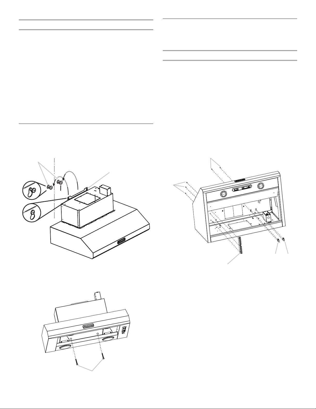
Install Range Hood
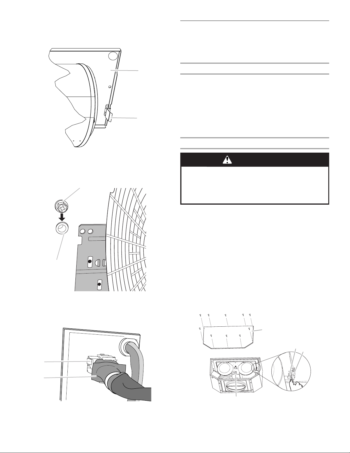
1. Remove the grease filter. See “Range Hood Care” section.
2. Using 2 or more people, hang range hood on 2 mounting
screws through the mounting slots on back of range hood.
A
B
Install Range Hood Internal Blower Motor
NOTE: Your range hood requires you to purchase either an
internal type or an in-line (external type) blower motor system.
See “Blower Motor System” in the “Accessories” section.
Prepare the Internal Blower System
IMPORTANT: Perform steps 1-4 before mounting the range
hood.
1. Remove grease filters from range hood. See the “Range
Hood Care” section in the Use and Care Guide.
2. Install the motor support bracket using three 4.2 x 8 mm
screws. Screw bracket to the inside top or back (alternate
location on some models), toward the left side of the range
hood.
3. Install motor spring clip using two 4.2 x 8 mm screws. Screw
spring clip to the inside top or back (alternate location on
some models) of the range hood at the proper location for the
selected motor system. Slide the mounting tab of the spring
clip through the slot in the panel and secure with the screws.
Use the inside set of mounting holes for the single motor
system. Use the outside set of mounting holes for the dual
motor system.
B
A. Mounting screws
B. Mounting slots
3. Level the range hood and tighten upper mounting screws.
4. Install 2 - 5 x 45 mm lower mounting screws and tighten.
A
E
D
C
A. 4.2 x 8 mm screws (3) for motor support bracket
B. 4.2 x 8 mm screws (2) for motor spring clip
C. Motor support bracket
D. Motor spring clip (single motor assembly location)
E. Motor spring clip (dual motor assembly location)
A
A. Lower mounting screws
8
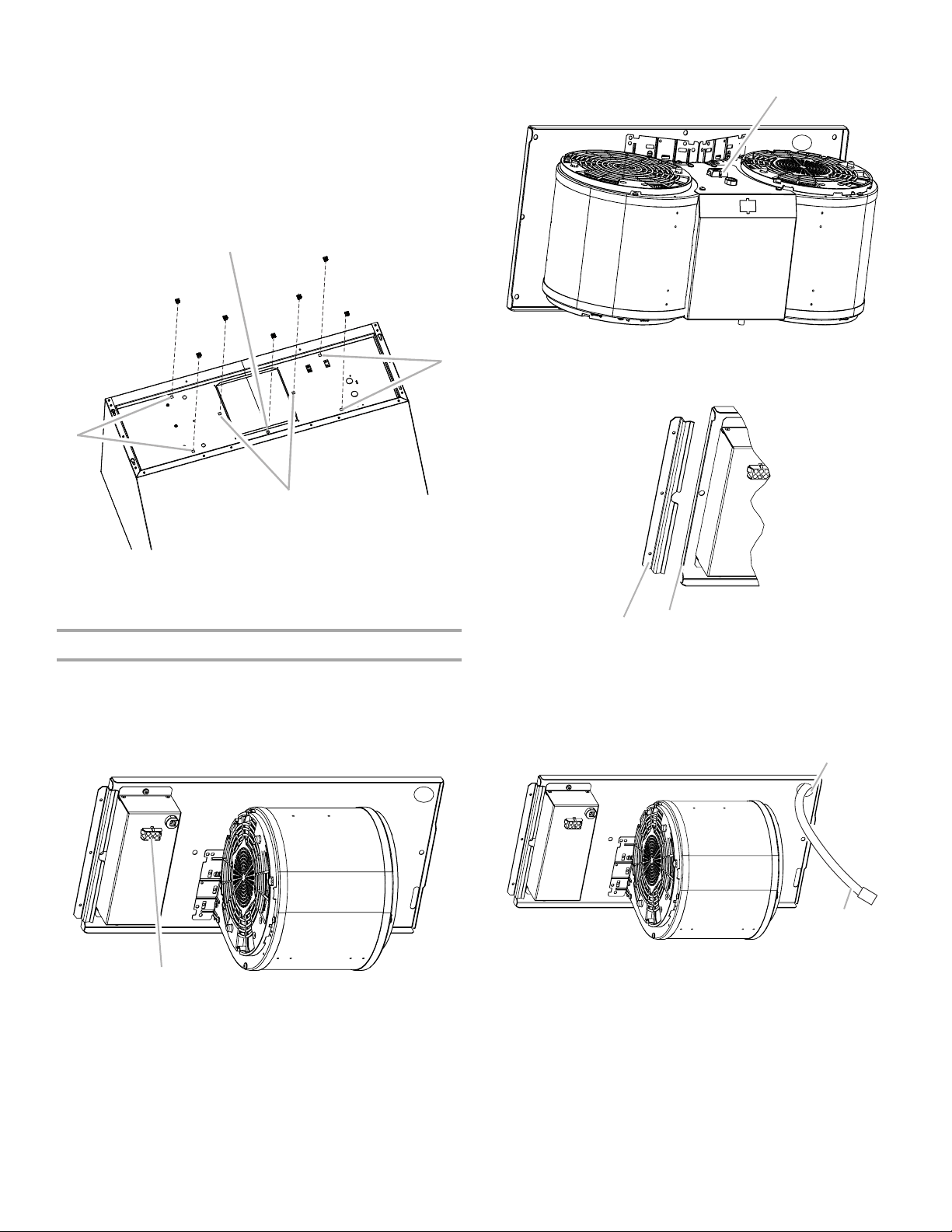
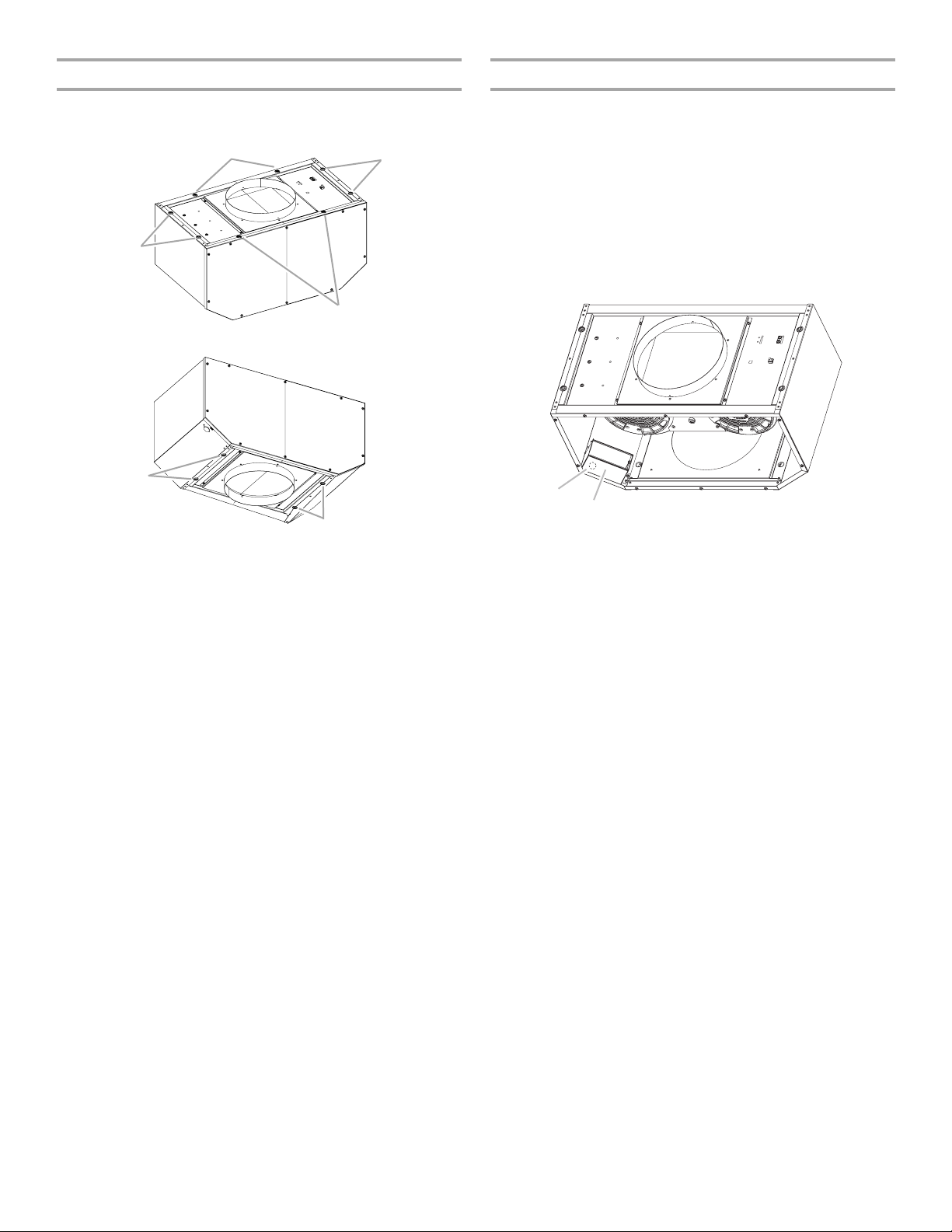
4. Install the 6 mm nuts to the outside top or outside back
A
(alternate location on some models) of the range hood at the
proper location for the selected motor system.
■ Two 6 mm nuts are required for the single motor system.
Clip nuts into the small square notches located at the left
and right end of the square vent opening.
■ Five 6 mm nuts are required for the dual motor system.
Clip nuts into the small square notches, one located in the
front of the square vent opening and the other four
located at the left and right ends of the square vent
opening.
A
A
B
Dual Blower Motor Assembly
A
A. Wiring connection
2. Slide the left mounting plate flange under the motor mounting
bracket.
A. Clip nut locations for dual motor assembly (5)
B. Clip nut locations for single motor assembly (2)
5. Mount range hood. See the “Install Range Hood” section.
Install Range Hood Internal Blower Motor
1. Install the range hood blower motor assembly inside the
range hood canopy with the wiring connection to the left for
the single motor system and to the front or top for the dual
motor system.
Single Blower Motor Assembly
A
A. Wiring connection
B
A
A. Motor mounting bracket
B. Mounting plate left flange
3. Run the power supply wires and connector from the range
hood through the hole in the right end of the motor mounting
plate.
A
B
A. Motor mounting plate hole
B. Power supply wires and connector
9
4. Push the right end of the motor mounting plate up and snap it
A
B
into the spring tab.
NOTE: The spring tab should be outside the slot in the
mounting plate.
A. Motor mounting plate
B. Spring clip
5. Align mounting holes and install 6 x 16 mm screws and
6.4 mm lock washers.
A
Install Range Hood In-Line (External Type)
Blower Motor
NOTE: Your range hood requires you to purchase either an
internal type or an in-line (external type) blower motor system.
See “Blower Motor System” in the “Accessories” section.
Prepare for Mounting the In-Line Blower System
The in-line blower system must be fastened to a secure structure
of the roof, ceiling, wall, floor, or new or existing frame
construction. The 4 holes on either the inlet (bottom) side or the
outlet (top) side of the blower must be used to mount the in-line
blower system to the structure.
NOTE: The mounting hole locations must span the studs.
Additional stud framing may be required. Plywood may be used
to span open areas between ceiling joists or roof rafters to aid
installation. This structure must be strong enough to support the
weight of the in-line blower system (50 lb [22.6 kg] min).
Prepare the In-line Blower System
WARNING
Excessive Weight Hazard
Use two or more people to move and install in-line
blower motor system.
Failure to do so can result in back or other injury.
B
A. Screw with lock washer
B. Mounting hole
6. Attach power supply connector from the range hood to the
connector on the blower motor assembly wiring box.
A
B
1. Using 2 or more people, move the in-line blower motor
system to the mounting location.
2. Remove the 10 screws from the front cover of the in-line
blower motor housing and set them aside.
3. Remove the front cover of the in-line blower motor housing
and set it aside.
NOTE: To make the blower motor housing easier to mount,
the blower motor assembly can be removed. If you do not
want to remove the blower motor assembly, proceed to
“Install In-line Blower System” in this section.
4. Disconnect the motor electrical plug from the blower motor
assembly.
5. Remove the screws that secure the blower motor assembly
to the in-line blower housing and set them aside.
6. Pull the spring clip to release the blower motor assembly.
Remove the blower motor assembly from the housing and
place it on a covered surface.
A
B
C
A. Wiring box connector
B. Power supply connector from range hood
7. Go to the “Make Electric Power Supply Connection to Range
Hood” section.
10
D
A. Front cover
B. Blower mounting screws
C. Spring clip
D. Motor electrical plug
Install In-line Blower System
A
Complete Preparation
NOTE: The blower motor housing can be mounted using 4 holes
from either the inlet side or the outlet side of the blower.
A
A
A
A
A
A. Mounting holes
1. Determine and make all necessary cuts for the vent system.
IMPORTANT: When cutting or drilling into the ceiling or wall,
do not damage electrical wiring or other hidden utilities.
2. Determine the location where the ¹⁄₂" (1.3 cm) wiring conduit
will be routed through the ceiling or wall between the in-line
blower and the range hood.
3. Drill a 1¹⁄₄" (3.2 cm) hole at this location.
4. Locate the electrical terminal boxes in the in-line blower
housing and range hood (see “Complete Preparation” in the
“Prepare Location” section). Remove the terminal box covers
and set the covers and screws aside.
B
A
A. Electrical terminal box
B. Electrical knockout
1. Position the in-line blower motor housing in its mounting
location and mark the 4 mounting hole locations.
2. Drill 4 mounting pilot holes using a ³⁄₁₆" (0.48 cm) drill bit.
3. Attach the in-line blower motor housing to the mounting
location with four 6 x 80 mm mounting screws and washers.
4. If it is removed, reinstall the blower motor assembly and
secure it with the screws previously removed.
5. If it is removed, reattach the motor electrical plug to the
connector on the blower motor assembly.
5. Remove the electrical knockout from the in-line blower
housing and range hood (see “Complete Preparation” in the
“Prepare Location” section) to prepare for the installation of
the UL listed or CSA approved ¹⁄₂" (1.3 cm) wiring conduit and
conduit connector.
6. With the range hood mounted (see the “Install Range Hood”
section), run the ¹⁄₂" (1.3 cm) wiring conduit between the inline blower motor housing and the range hood. Pull enough
¹⁄₂" (1.3 cm) wiring conduit to allow for easy connection to the
terminal boxes in the in-line blower housing and range hood.
7. Run the six 18 AWG wires through the ¹⁄₂" (1.3 cm) wiring
conduit and conduit connectors and into the terminal boxes
on the in-line blower housing and range hood. Leave enough
wire length in each terminal box to make the wiring
connections.
8. Install the conduit connectors and conduit to the in-line
blower housing and range hood electrical terminal boxes.
9. Connect the vent system to the range hood and in-line blower
system and seal all joints with clamps.
11
Make Electrical Connections for In-Line Blower Motor System
WARNING
Electrical Shock Hazard
Disconnect power before servicing.
Replace all parts and panels before operating.
Failure to do so can result in death or electrical shock.
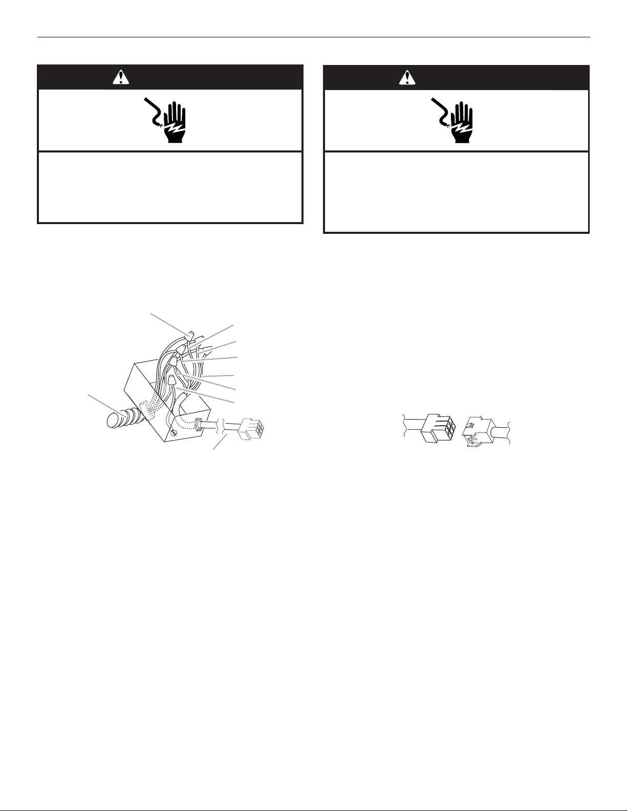
Electrical Connection Inside In-line Blower System
1. Disconnect power.
2. Connect the wires from the wiring conduit to the wires from
the motor electrical plug cable inside the in-line blower
housing terminal box.
B
C
D
E
F
A
G
H
WARNING
Electrical Shock Hazard
Electrically ground blower.
Connect ground wire to green and yellow ground wire
in terminal box.
Failure to do so can result in death or electrical shock.
8. Connect the green (or yellow/green) ground wire to the
green/yellow ground wire (H) in the terminal box using UL
listed wire connectors.
9. Reinstall the in-line blower terminal box cover and screw.
10. Reinstall the front cover of the in-line blower housing and
secure it with 10 mounting screws.
Electrical Connection Inside Range Hood Between In-line
Blower System and Range Hood
1. With the range hood mounted (see the “Install Range Hood”
section), locate the wiring cable connector inside the range
hood.
2. Connect the 6-wire connector assembly supplied with the
in-line blower motor system to the mating cable connector
from the range hood.
I
A. UL listed or CSA approved
¹⁄₂
" (1.3 cm) wiring conduit
B. UL listed wire connectors
C. Black wires
D. White wires
E. Red wires
3. Use UL listed wire connectors and connect the black wires
(C) together.
4. Use UL listed wire connectors and connect the white wires
(D) together.
5. Use UL listed wire connectors and connect the red wires (E)
together.
6. Use UL listed wire connectors and connect the blue wires (F)
together.
7. Use UL listed wire connectors and connect the gray wires (G)
together.
F. B lu e w ire s
G. Gray wires
H. Green (or yellow/green)
and green/yellow wires
I. Motor electrical plug cable
3. Locate the terminal box inside the range hood and install a
¹⁄₂" (1.3 cm) UL listed or CSA approved strain relief (see
“Complete Preparation” in the “Prepare Location” section).
4. Run the wire ends from the 6-wire connector assembly
through the ¹⁄₂" (1.3 cm) strain relief, leaving enough wire
length to make the wiring connections. Tighten the strain
relief screws.
5. Connect the wires from the 6-wire connector assembly to the
wires from the wiring conduit inside the range hood terminal
box.
6. Connect the same color wires to each other (black to black,
white to white, etc.) using UL listed wire connectors.
NOTE: Connect the green (or green/yellow) ground wire from
the wiring conduit to the green (or bare) ground wire from the
home power supply using UL listed wire connectors (see the
“Make Electrical Power Supply Connection to Range Hood”
section).
12
 Loading...