

KitchenAid KXW8730Y, KXW8736Y Dimensions Guide
30", 36" and 48" (76.2 cm, 91.4 cm and 121.9 cm) Commercial
Style Wall-Mount Canopy Range Hood
PRODUCT MODEL NUMBERS
KXW8730Y KXW8736Y KXW8748Y
Because Whirlpool Corporation policy includes a continuous commitment to improve
our products, we reserve the right to change materials and specifications without notice.
Dimensions are for planning purposes only. For complete details, see Installation
Instructions packed with product. Specifications subject to change without notice.
Ref. W10331007B
3/30/11
INSTALLATION DIMENSIONS
Electrical Requirements:
●
A 120 volt, 60 Hz., AC only, 15-amp, fused electrical circuit is
required.
●
If the house has aluminum wiring, follow the procedure below:
1. Connect a section of solid copper wire to the pigtail
leads.
2. Connect the aluminum wiring to the added section
of copper wire using special connectors and/or
tools designed and UL listed for joining copper to
aluminum.
Follow the electrical connector manufacturer's recommended
procedure. Aluminum/copper connection must conform with local
codes and industry accepted wiring practices.
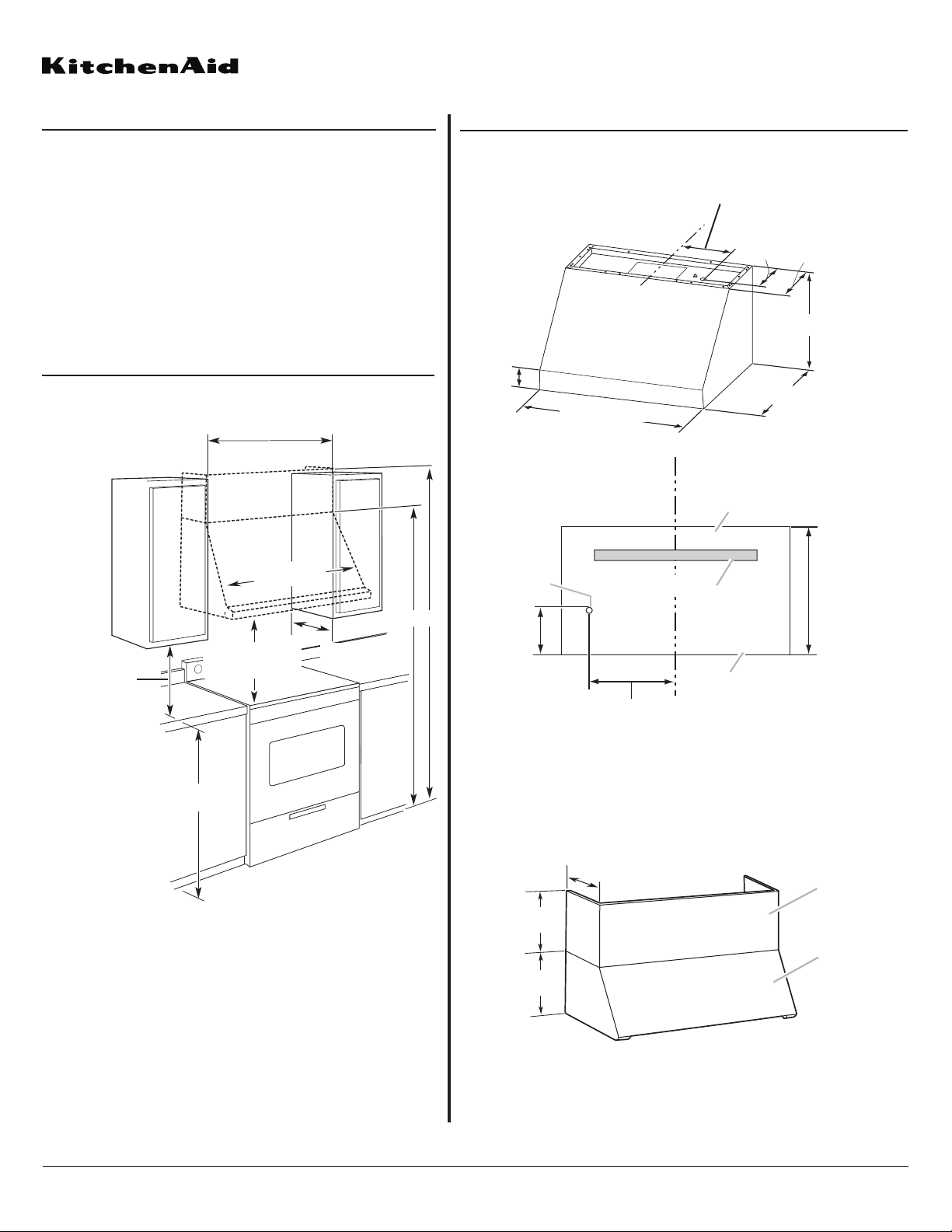
IMPORTANT:
Minimum distance “X”: 24" (61 cm) from electric cooking surfaces
Minimum distance “X”: 30" (76.2 cm) from gas cooking surfaces
Suggested maximum distance “X”: 36" (91.4 cm)
PRODUCT DIMENSIONS
A. Knockout into terminal box
B. Top of hood
C. Wood support
D. Bottom of hood
A
B
C
CL
18¹³⁄₁₆" (47.8 cm) for 48" (121.9 cm) Hood
12¹³⁄₁₆" (32.5 cm) for 36" (91.4 cm) Hood
9¹³⁄₁₆" (24.9 cm) for 30" (76.2 cm) Hood
18"
(45.7 cm)
D
9⁵⁄₈"
(24.4 cm)
Front view
Back view
Optional Full-Width Duct Cover Installations
A. Optional full-width duct cover
B. Range hood
CL
18¹⁄₁₆" (45.9 cm) for 48" (121.9 cm) Hood
12¹⁄₁₆" (30.6 cm) for 36" (91.4 cm) Hood
9¹⁄₁₆" (23.0 cm) for 30" (76.2 cm) Hood
18" (45.7 cm)
12" (30.5 cm)
30" (76.2 cm)
36" (91.4 cm)
48" (121.9 cm)
3³⁄₁₆"
(8.1 cm)
6¹⁄₂" (16.5 cm)
25" (63.5 cm)
12"
(30.5 cm)
18"
(45.7 cm)
12"
(30.5 cm)
A
B
Page 1 of 2
®
30" (76.2 cm), 36" (91.4 cm),
or
48"
cabinet opening width
(If installed between cabinets)
cm)
(121.9
18" (45.7 cm)
clearance upper
cabinet to countertop
min.
c
tneV
C
Bottom of canopy
to cooking surface
36" (91.4 cm)
countertop height
)desu fi( revo
Min. cabinet
opening width
ypona
X
A. For installations with canopy
only:
78" (198.1 cm) minimum above
electric cooking surface
84" (213.4 cm) minimum above
gas cooking surface
B. For installations with optional
duct cover:
90" (228.6 cm) minimum
above electric cooking
surface
96" (243.8 cm) minimum
above gas cooking surface
A B
13" (33.0 cm)
Because Whirlpool Corporation policy includes a continuous commitment to improve
our products, we reserve the right to change materials and specifications without notice.
Dimensions are for planning purposes only. For complete details, see Installation
Instructions packed with product. Specifications subject to change without notice.
Ref. W10331007B
3/30/11
Page 2 of 2
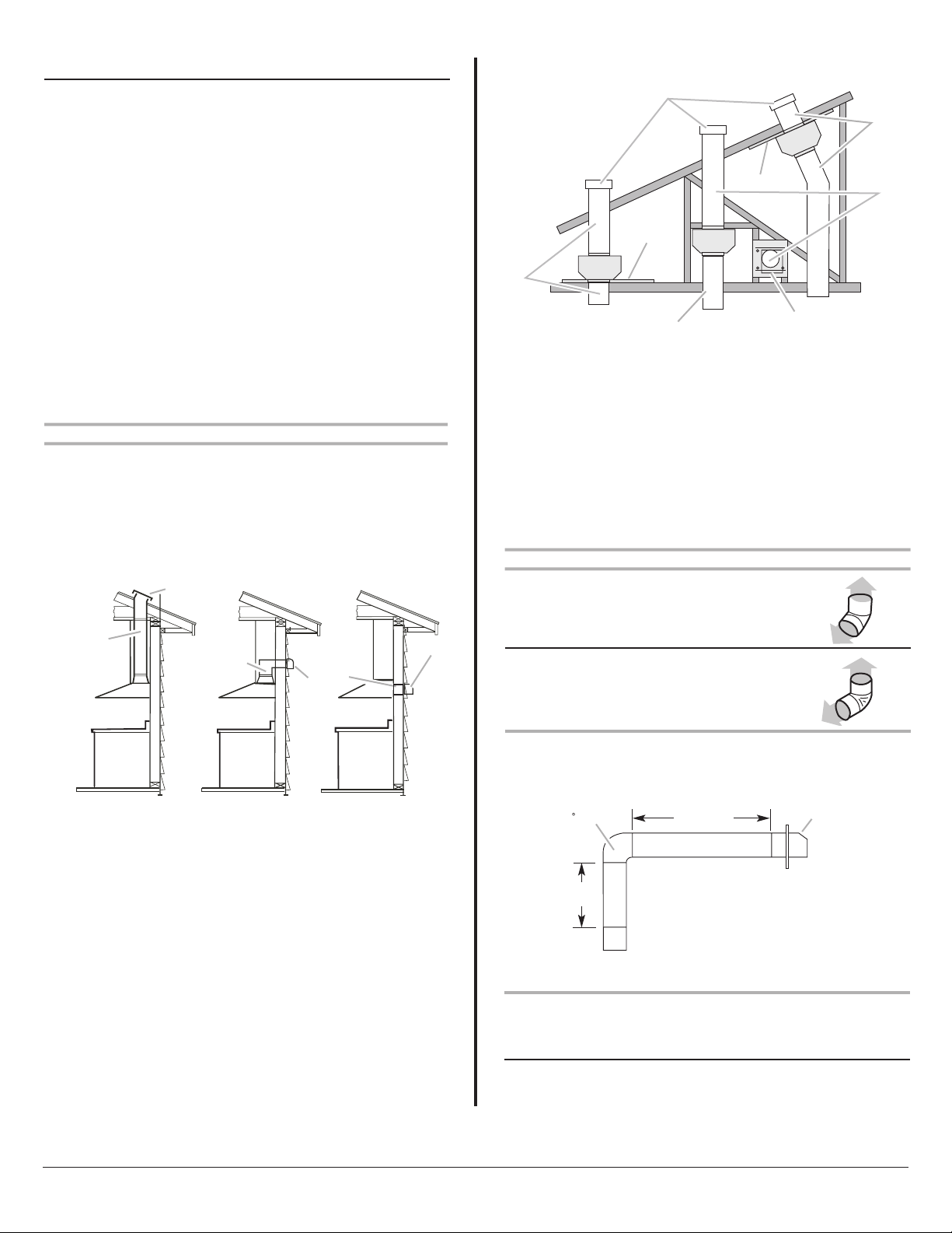
Calculating Vent System Length
To calculate the length of the system you need, add the equivalent feet
(meters) for each vent piece used in the system.
Vent Piece Equivalent Length
45° elbow 2.5 ft
(0.8 m)
90° elbow 5.0 ft
(1.5 m)
The maximum equivalent vent lengths are:
10" (25.4 cm) round vents - 60 ft (18.3 m)
The following example falls within the maximum recommended vent
length.
1 - 90° elbow = 5.0 ft (1.5 m)
1 - wall cap = 0.0 ft (0.0 m)
8 ft (2.4 m) straight = 8.0 ft (2.4 m)
Length of system = 13.0 ft (3.9 m)
VENTING REQUIREMENTS
●
Vent system must terminate to the outdoors.
●
Do not terminate the vent system in an attic or other enclosed area.
●
Do not use 4" (10.2 cm) laundry-type wall caps.
●
Use metal vent only. Rigid metal vent is recommended. Plastic or
metal foil vent is not recommended.
●
The length of vent system and number of elbows should be kept to a
minimum to provide efficient performance.
For the most efficient and quiet operation:
●
Use no more than three 90° elbows.
●
Make sure there is a minimum of 24" (61.0 cm) of straight vent
between the elbows if more than 1 elbow is used.
●
Do not install 2 elbows together.
●
Use clamps to seal all joints in the vent system.
●
The vent system must have a damper. If the roof or wall cap has a
damper, do not use the damper supplied with the range hood.
●
Use caulking to seal exterior wall or roof opening around the cap.
●
The size of the vent should be uniform.
Venting Methods
Typical Internal Blower Motor System Venting Installations
A 10" (25.4 cm) round vent system is needed for installation (not
included). The hood exhaust opening is 10" (25.4 cm) round.
NOTE: Flexible vent is not recommended. Flexible vent creates back
pressure and air turbulence that greatly reduce performance.
Vent system can terminate either through the roof or wall.
Typical In-line Blower Motor System Venting Installations
A
Roof Venting Wall Venting Wall Venting
A
C
A
E
D
D
A
B
A. 10" (25.4 cm) round vent
B. Mount on top of ceiling joists.
C. Roof caps
D. Plywood (optional for some installations)
E. Mount on underside of roof rafters.
F. Mount from cross-members tied to trusses.
G. Duct horizontal; mount to cross-members
tied to trusses.
H. Wall cap
F
A
G
H
B
A. Roof cap
B. 10" (25.4 cm)
round vent
B
A. Wall cap
B. 10" (25.4 cm)
round vent
B
A
A. Wall cap
B. 10" (25.4 cm)
round vent
A
Example vent system
90 elbow
2 ft
(0.6 m)
6 ft (1.8 m)
Wall cap
 Loading...