

Kitchenaid KXU8036YSS Owners Manual
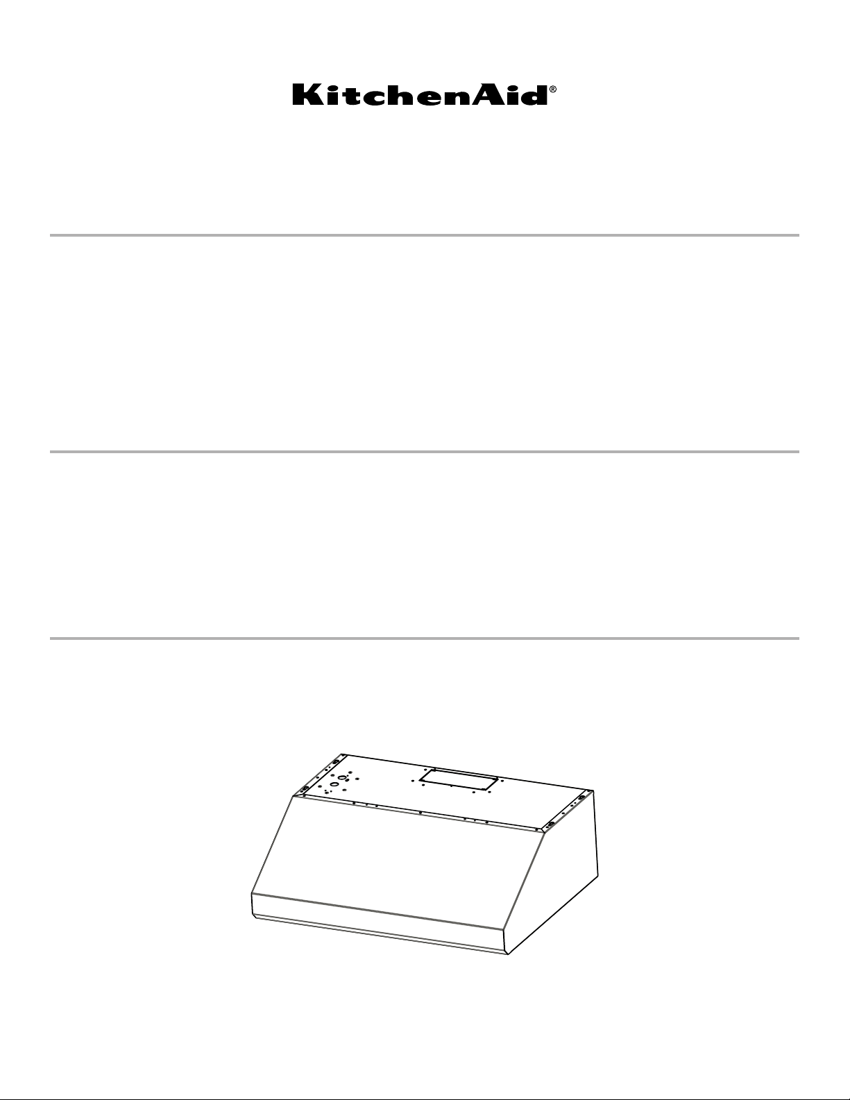
30" (76.2 CM) AND 36" (91.4 CM)
COMMERCIAL STYLE
WALL-MOUNT CANOPY RANGE HOOD
Installation Instructions and Use and Care Guide
For questions about features, operation/performance, parts, accessories,
In Canada, for assistance, installation, and service, call: 1-800-807-6777 or visit our website at www.kitchenaid.ca.
or service, call: 1-800-422-1230
or visit our website at www.kitchenaid.com.
HOTTE D’EXTRACTION À MONTAGE
MURALDE STYLE COMMERCIAL DE
30" (76,2 CM) ET 36" (91,4 CM)
Instructions d’installation et Guide d’utilisation et d’entretien
Au Canada, pour assistance, installation ou service composez le 1-800-807-6777
ou visitez notre site web à www.kitchenaid.ca.
CAMPANA DE COCINA CON ESCUDETE
DEMONTAJE EN LA PARED, COMERCIAL
30”(76,2 CM) Y 36” (91,4 CM)
Instrucciones de instalación y Manual de uso y cuidado
Si tiene preguntas respecto a características, funcionamiento, rendimiento, piezas, accesorios o servicio técnico, llame al: 1-800-422-1230
En Canadá, para obtener asistencia, instalación y servicio, llame al: 1-800-807-6777 o visite nuestro sitio web en www.kitchenaid.ca.
Table of Contents/Table des matières/Índice ����������������������������������������������������������������������������������������2
o visite nuestro sitio web en www.kitchenaid.com.
IMPORTANT: READ AND SAVE THESE INSTRUCTIONS. FOR RESIDENTIAL USE ONLY.
IMPORTANT : LIRE ET CONSERVER CES INSTRUCTIONS. POUR UTILISATION RÉSIDENTIELLE UNIQUEMENT.
IMPORTANTE: LEA Y GUARDE ESTAS INSTRUCCIONES. SÓLO PARA USO RESIDENCIAL.
LI3Y4C/W11165203A

TABLE OF CONTENTS
RANGE HOOD SAFETY .................................................................3
INSTALLATION REQUIREMENTS .................................................5
Tools and Parts �����������������������������������������������������������������������������5
Location Requirements ����������������������������������������������������������������5
Venting Requirements ������������������������������������������������������������������6
Electrical Requirements ���������������������������������������������������������������7
INSTALLATION INSTRUCTIONS ...................................................8
Prepare Location ��������������������������������������������������������������������������8
Install Range Hood ���������������������������������������������������������������������10
Make Electrical Connection �������������������������������������������������������10
Install Vent Covers (Optional) �����������������������������������������������������11
Complete Installation �����������������������������������������������������������������11
TABLE DES MATIERES
SÉCURITÉ DE LA HOTTE DE CUISINIÈRE ...............................16
EXIGENCES D’INSTALLATION ...................................................18
Outils et pièces ���������������������������������������������������������������������������18
Exigences d’emplacement ���������������������������������������������������������18
Exigences concernant l’évacuation �������������������������������������������19
Spécications électriques ����������������������������������������������������������20
INSTRUCTIONS D’INSTALLATION .............................................21
Préparation de l’emplacement ���������������������������������������������������21
Installation de la hotte ����������������������������������������������������������������23
Raccordement électrique �����������������������������������������������������������24
Installation des cache-conduits (facultatif) ��������������������������������24
Achever l’installation ������������������������������������������������������������������24
RANGE HOOD USE ......................................................................11
Range Hood Controls ����������������������������������������������������������������11
RANGE HOOD CARE ...................................................................12
Cleaning �������������������������������������������������������������������������������������12
WIRING DIAGRAM .......................................................................13
WHIRLPOOL SERVICE ................................................................14
WARRANTY ..................................................................................15
UTILISATION DE LA HOTTE .......................................................25
Commandes de la hotte de cuisinière ���������������������������������������25
ENTRETIEN DE LA HOTTE .........................................................26
Nettoyage �����������������������������������������������������������������������������������26
SCHÉMA DE CÂBLAGE ...............................................................27
SERVICE WHIRLPOOL ................................................................28
GARANTIE .....................................................................................29
ÍNDICE
SEGURIDAD DE LA CAMPANA DE COCINA ............................30
REQUISITOS DE INSTALACIÓN .................................................32
Herramientas y piezas ����������������������������������������������������������������32
Requisitos de ubicación �������������������������������������������������������������32
Requisitos de ventilación �����������������������������������������������������������33
Requisitos eléctricos ������������������������������������������������������������������34
INSTRUCCIONES DE INSTALACIÓN .........................................35
Preparación de la ubicación ������������������������������������������������������35
Instalación de la campana para cocina �������������������������������������37
Conexión del suministro eléctrico ����������������������������������������������37
Instalación de las cubiertas de la ventilación (opcional) �����������38
Completar la instalación ������������������������������������������������������������38
USO DE LA CAMPANA PARA COCINA ......................................38
Controles de la campana de cocina ������������������������������������������38
CUIDADO DE LA CAMPANA PARA COCINA ............................39
Limpieza �������������������������������������������������������������������������������������39
DIAGRAMA DE CABLEADO ........................................................40
WHIRLPOOL SERVICE ................................................................41
GARANTÍA.....................................................................................42
2
RANGE HOOD SAFETY
Your safety and the safety of others are very important.
We have provided many important safety messages in this manual and on your appliance. Always read and obey all safety
messages.
This is the safety alert symbol.
This symbol alerts you to potential hazards that can kill or hurt you and others.
All safety messages will follow the safety alert symbol and either the word “DANGER” or “WARNING.”
These words mean:
You can be killed or seriously injured if you don't immediately
DANGER
WARNING
All safety messages will tell you what the potential hazard is, tell you how to reduce the chance of injury, and tell you what can
happen if the instructions are not followed.
State of California Proposition 65 Warnings:
WARNING: This product contains one or more chemicals known to the State of California to cause cancer.
WARNING: This product contains one or more chemicals known to the State of California to cause birth defects or other
reproductive harm.
follow instructions.
You
can be killed or seriously injured if you don't
instructions.
follow
3
IMPORTANT SAFETY INSTRUCTIONS
This appliance is not intended for use by people
(including children) whose physical, sensory or mental
capacities are different or impaired or who lack the
necessary experience or knowledge/expertise to do so,
unless such persons are supervised or are trained to
operate the appliance by a person who accepts
responsibility for their safety.
READ AND SAVE THESE INSTRUCTIONS
4
INSTALLATION REQUIREMENTS
Tools and Parts
Gather the required tools and parts before starting installation�
Read and follow the instructions provided with any tools listed
here�
Tools needed
■ Level
■ Drill with 1
5/16" (7�9 mm) drill bits
■ Pencil
■ Wire stripper or utility knife
■ Tape measure or ruler
■ Pliers
■ Caulking gun and weatherproof caulking compound
■ Jigsaw or keyhole saw
■ Flat-blade screwdriver
■ Metal snips
■ Phillips screwdriver
■ Metric hex key set
Parts needed
■ Home power supply cable
■ 1/2" (12�7 mm) UL Listed or CSA approved strain relief
■ 3 UL Listed wire connectors
■ 1 wall or roof cap
■ Metal vent system
■ Vent clamps/duct tape as required
Parts supplied
Remove parts from packages� Check that all parts are included�
■ Hood canopy assembly with ventilator and light bulbs
installed
1
■ 3
/4" x 10" (8�3 cm x 25�4 cm) rectangular vent connector
■ 2 metal grease lters for 30" (76�2 cm) model
■ 3 metal grease lters for 36" (91�4 cm) model
■ T20
■ 4 - 5 x 45 mm mounting screws
■ 6 - 4�5 x 13 mm screws
■ 3 - 4 x 8 mm screws
■ 4 - 10 x 50 wall anchors
1
/4" (3�0 cm), 3/16" (4�8 mm), 1/8" (3�0 mm), and
®
Torx®† adapter
Location Requirements
IMPORTANT: Observe all governing codes and ordinances�
Have a qualied technician install the range hood� It is the
installer’s responsibility to comply with installation clearances
specied on the model/serial rating plate� The model/serial
rating plate is located behind the left lter on the rear wall of the
venthood�
Canopy hood location should be away from strong draft areas,
such as windows, doors, and strong heating vents�
Cabinet opening dimensions that are shown must be used�
Given dimensions provide minimum clearance�
Grounded electrical outlet is required� See the “Electrical
Requirements” section�
The canopy hood is factory set for venting through the roof
orwall�
All openings in ceiling and wall where canopy hood will be
installed must be sealed�
For Mobile Home Installations
The installation of this range hood must conform to the
Manufactured Home Construction Safety Standards, Title 24
CFR, Part 328 (formerly the Federal Standard for Mobile Home
Construction and Safety, Title 24, HUD, Part 280) or when such
standard is not applicable, the standard for Manufactured Home
Installation 1982 (Manufactured Home Sites, Communities and
Setups) ANSI A225�1/NFPA 501A, or latest edition, or with local
codes�
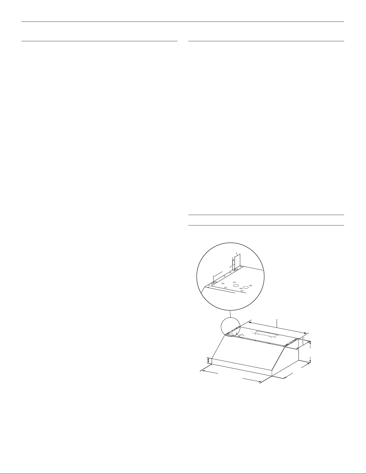
Product Dimensions
Front View
2⁹⁄₁₆"
(6.5 cm)
³⁄₈"
(1.0 cm)
7½"
(19.0 cm)
29¹⁄₈" (74.0 cm): 30" (76.2 cm) models
35¹⁄₈" (89.2 cm): 36" (91.4 cm) models
12"
(30.5 cm)
10"
3¹⁄₈"
(7.9 cm)
30" (76.2 cm)
36" (91.4 cm)
(25.4 cm)
23" (58.4 cm)
†®TORX and T20 are registered trademarks of Acument Intellectual Properties, LLC�
5
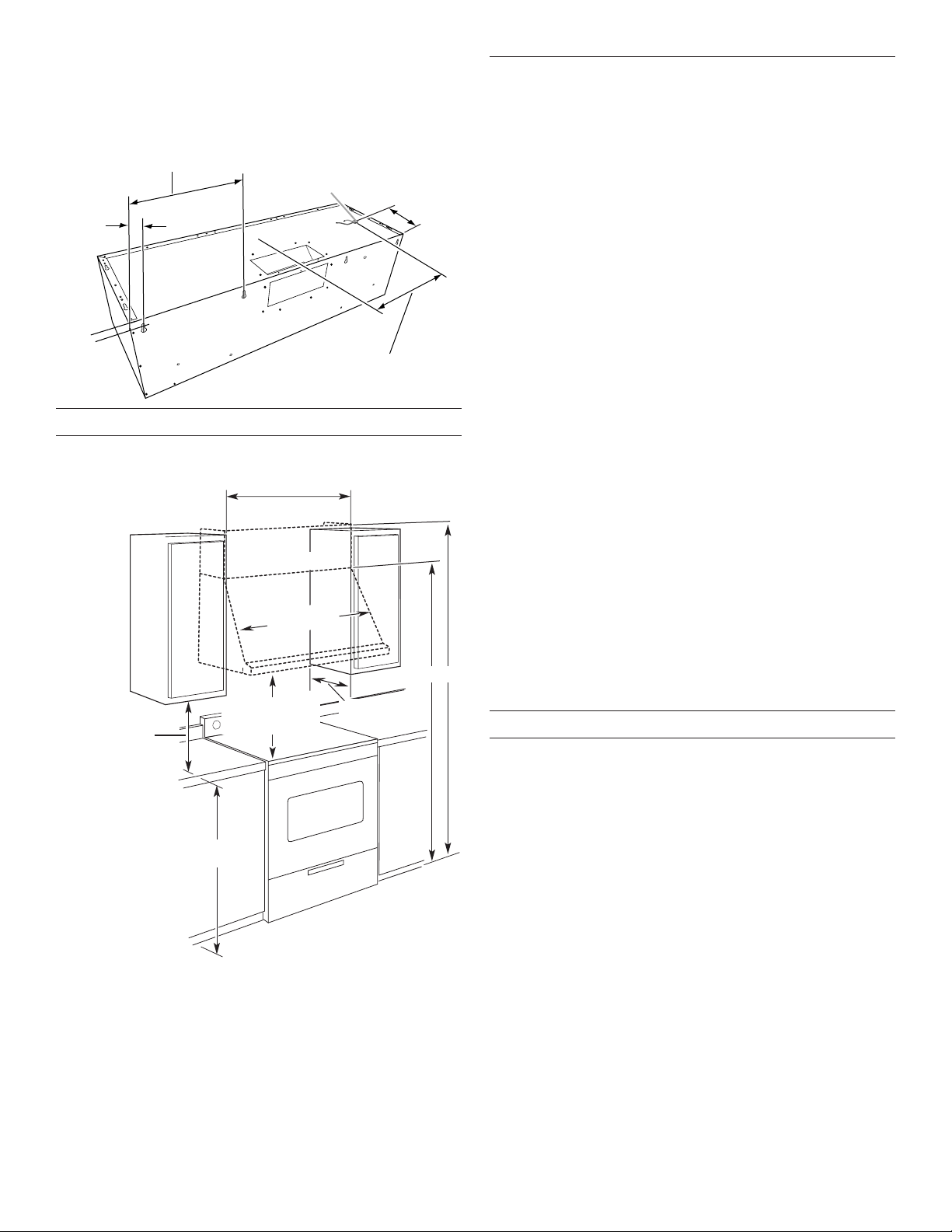
Back View
(20.0 cm)
30" (76.2 cm) models: 12¼" (31.1 cm)
(1.6 cm)
18"
cabinet
30" (76.2 cm) or 36" (91.4 cm)
7" (17.8 cm): 30" (76.2 cm) models
9⁷⁄₈" (25.0 cm): 36" (91.4 cm) models
1¹⁄₈"
(2.9 cm)
⁵⁄₈"
Cabinet Dimensions
36" (91.4 cm) models: 15" (38.1 cm)
Wiring knockout
7⁷⁄₈"
12³⁄₁₆" (31.0 cm)
Venting Requirements
■ Vent system must terminate to the outdoors�
■ Do not terminate the vent system in an attic or other
enclosed area�
■ Do not use a 4" (10�2 cm) laundry-type wall cap�
■ Use metal vent only� Rigid metal vent is recommended�
■ The length of vent system and number of elbows should be
kept to a minimum to provide efcient performance�
For the most efficient and quiet operation:
■ Use no more than three 90° elbows�
■ Make sure there is a minimum of 24" (61�0 cm) of straight
vent between the elbows if more than one elbow is used�
■ Do not install two elbows together�
■ Use clamps or duct tape to seal all joints in the vent system�
■ The vent system must have a damper� If roof or wall cap has
a damper, do not use damper supplied with the range hood�
■ Use caulking to seal exterior wall or roof opening around
thecap�
■ The size of the vent should be uniform�
(45.7 cm) min.
clearance upper
to countertop
cabinet opening width
(If installed between cabinets)
Duct cover (if used)
Min. cabinet
opening width
Canopy
X
countertop height
Bottom of canopy
to cooking surface
36" (91.4 cm)
13" (33.0 cm)
Cold Weather Installations
An additional back draft damper should be installed to minimize
backward cold air ow and a thermal break should be installed
to minimize conduction of outside temperatures as part of the
vent system� The damper should be on the cold air side of the
thermal break�
The break should be as close as possible to where the vent
system enters the heated portion of the house�
Makeup Air
Local building codes may require the use of makeup air systems
when using ventilation systems greater than specied CFM of air
movement� The specied CFM varies from locale to locale�
A
B
Consult your HVAC professional for specic requirements in
yourarea�
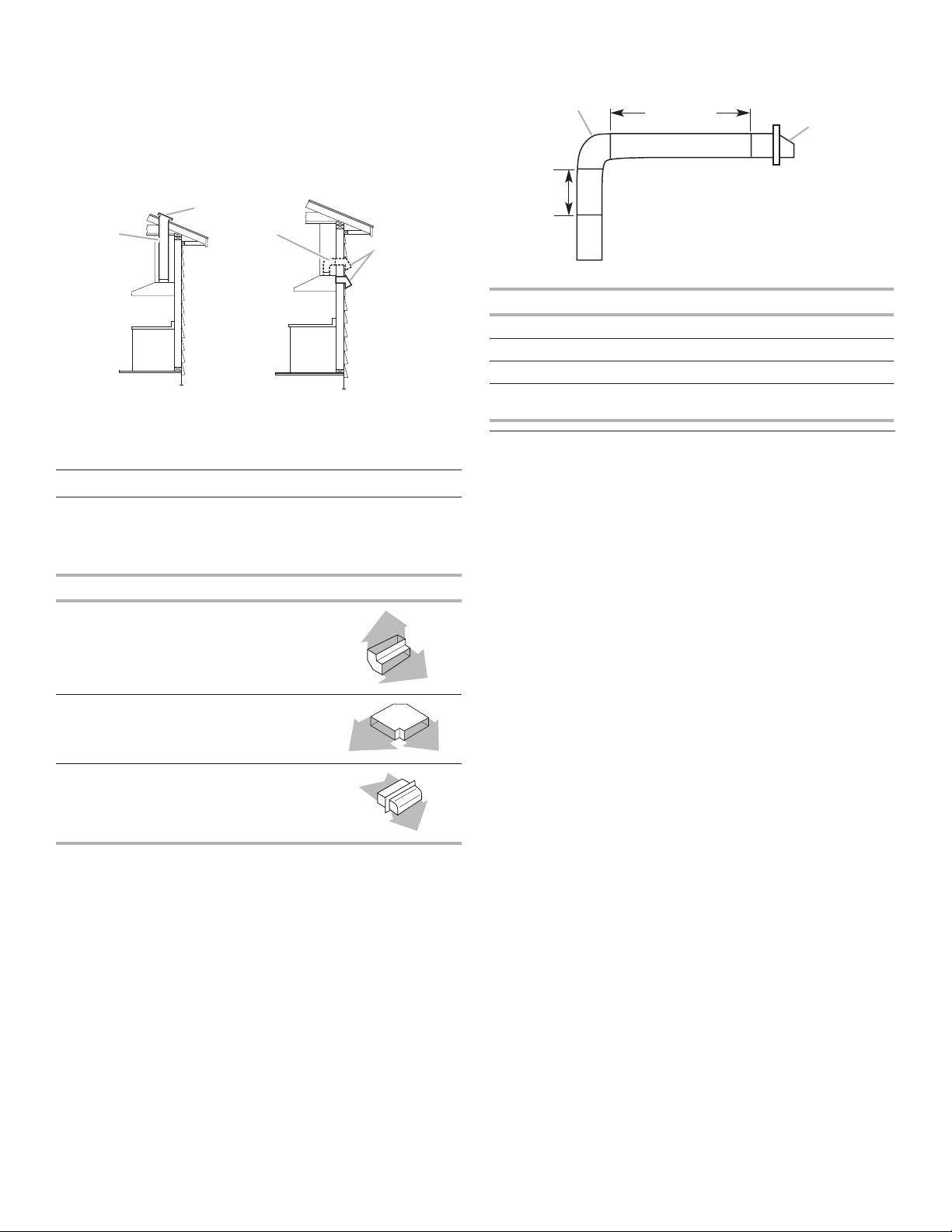
Venting Methods
This canopy hood is factory set for venting through the roof
orwall�
A 31/4" x 10" (8�3 x 25�4 cm) rectangular vent system is needed
for installation (not included)� The hood exhaust opening is
31/4"x 10" (8�3 x 25�4 cm)� Vent system can terminate either
through the roof or wall� To vent out of the top of the range hood
and through a wall, a 90° elbow is needed� See “Install Range
Hood” section for details for installing the damper�
NOTE: Flexible vent is not recommended� Flexible vent
creates back pressure and air turbulence that gently reduce
performance�
A. For installations with canopy
only. 70" (177.8 cm) minimum
above electric cooking surface.
76" (193.0 cm) minimum above
gas cooking surface.
B. For installations with optional
duct cover. 82" (208.3 cm)
minimum above electric
cooking surface. 88”
(223.5 cm) minimum above
gas cooking surface.
IMPORTANT: Minimum distance “X” : 24" (61�0 cm) to electric
cooking surface and 30" (76�2 cm) to gas cooking surface�
Suggested maximum distance “X” : 36" (91�4 cm)�
6
B
A
B
3¹⁄₄" x 10"
(0.6 m)
Rear discharge
This range hood can be vented directly out the back using the
31/4" x 10" (8�3 cm x 25�4 cm) rectangular damper (supplied)
along with a 31/4" x 10" (8�3 cm x 25�4 cm) rectangular vent
system (not supplied)� See the “Install Range Hood” section for
details for installing the damper�
Roof Venting
Wall Venting
(top or rear discharge)
A. Roof cap
B. 31/4" x 10" (8.3 x 25.4cm)
rectangular metal vent
A. Wall cap
B. 31/4" x 10" (8.3 x 25.4cm)
rectangular metal vent
Calculating Vent System Length
To calculate the length of the system you need, add the
equivalent feet (meters) for each vent piece used in the system�
31/4" x 10" (8.3 x 25.4 cm) Vent System
Vent Piece
31/4" x 10" (8�3 cm x 25�4 cm)
90° elbow
31/4" x 10" (8�3 x 25�4 cm)
at elbow
31/4" x 10" (8�3 x 25�4 cm)
wall cap
5�0 ft
(1�5 m)
12�0 ft
(3�7 m)
0�0 ft
(0�0 m)
Example vent system
elbow
6 ft (1.8 m)
Wall cap
(8.3 x 25.4 cm)
2 ft
A
Maximum Recommended Length = 35 ft (10.7 m)
1 - 90° elbow = 5�0 ft (1�5 m)
8 ft (2�4 m) straight = 8�0 ft (2�4 m)
1 - wall cap = 0�0 ft (0�0 m)
Length of 31/4" x 10" (8�3 cm x 25�4 cm)
= 13�0 ft (3�9 m)
system
Electrical Requirements
Observe all governing codes and ordinances�
Ensure that the electrical installation is adequate and in
conformance with National Electrical Code, ANSI/NFPA 70
(latest edition), or CSA Standards C22�1-94, Canadian Electrical
Code, Part 1 and C22�2 No� 0-M91 (latest edition) and all local
codes and ordinances�
If codes permit and a separate ground wire is used, it is
recommended that a qualied electrician determine that the
ground path is adequate�
A copy of the above code standards can be obtained from:
National Fire Protection Association
One Batterymarch Park
Quincy, MA 02269
CSA International
8501 East Pleasant Valley Road
Cleveland, OH 44131-5575
■ A 120 volt, 60 Hz�, AC only, 15-amp, fused electrical circuit is
required�
■ If the house has aluminum wiring, follow the procedure
below:
Connect the aluminum wiring using special connectors
and/or tools designed and UL listed for joining copper to
aluminum�
Follow the electrical connector manufacturer’s recommended
procedure� Aluminum/copper connection must conform with
local codes and industry accepted wiring practices�
■ Wire sizes and connections must conform with the rating of
the appliance as specied on the model/serial rating plate�
The model/serial plate is located behind the lter on the rea
wall of the range hood�
■ Wire sizes must conform to the requirements of the National
Electrical Code, ANSI/NFPA 70 (latest edition), or CSA
Standards C22� 1-94, Canadian Electrical Code, Part 1 and
C22�2 No� 0-M91 (latest edition) and all local codes and
ordinances�
7
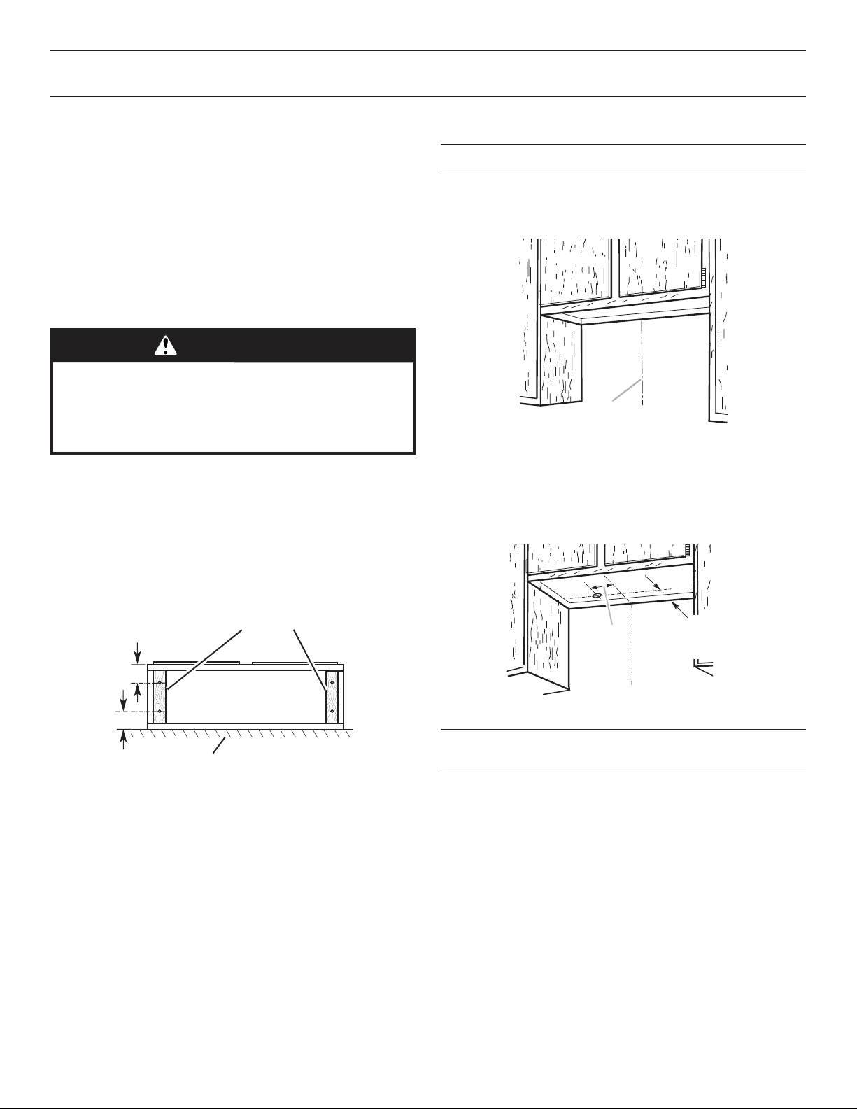
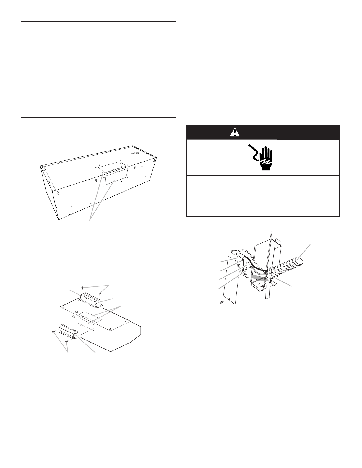
INSTALLATION INSTRUCTIONS
Wall
Wood filler strips
3" (7.6 cm)
" (20.0 cm)
Prepare Location
■ It is recommended that the vent system be installed before
hood is installed�
■ If you are installing a full width duct cover, follow the
instructions included with that product�
■ Before making cutouts, make sure there is proper clearance
within the ceiling or wall for exhaust vent�
■ Check your ceiling height and the hood height maximum
before you select your hood�
1. Disconnect power�
2. Determine which venting method to use: roof or wall�
3. Select a at surface for assembling the range hood� Place
covering over that surface�
WARNING
Excessive Weight Hazard
Use two or more people to move and install
range hood.
Failure to do so can result in back or other injury.
Determine Wiring Hole Location
Cut only one 11/4" (3�2 cm) diameter wiring access hole� See
Step 2 for wiring hole location instructions�
1. Determine and clearly mark a vertical centerline on the wall
and cabinet in the area the vent opening will be made�
A
A. Centerline
4. Using two or more people, lift range hood onto covered
surface�
NOTE: This range hood can be mounted to the cabinets or
to the wall�
For Cabinet Installations
1. If cabinet has recessed bottom, add wood ller strips on
each side� Install screws to attach ller strips in locations
shown�
(recessed cabinet
3" (7.6 cm)
bottoms only)
Cabinet
bottom
2. To wire through top:
Mark a line distance “A” from the left of the centerline on the
underside of the cabinet� Mark the point on this line that is
77/8" (20�0 cm) from back wall� Drill a 11/4" (3�2 cm) diameter
hole through the cabinet at this point�
7⁷⁄₈
A
Centerline
A. 123/16" (31.0 cm)
from wall,
not cabinet
frame
Cut Openings for 31/4" x 10" (8.3 cm x 25.4 cm)
Rectangular Vent System
Roof Venting
To make a 4" x 101/2" (10.2 cm x 26.7 cm) rectangular cutout
on the underside of cabinet top and bottom:
1. Mark lines 1/2" (1�3 cm) and 41/2" (11�4 cm) from the back
wall on the centerline of the underside of cabinet�
2. Mark lines 51/4" (13�3 cm) to the right and left of the
centerline on the underside of cabinet�
3. Use saber or keyhole saw to cut a rectangular opening for
vent�
8
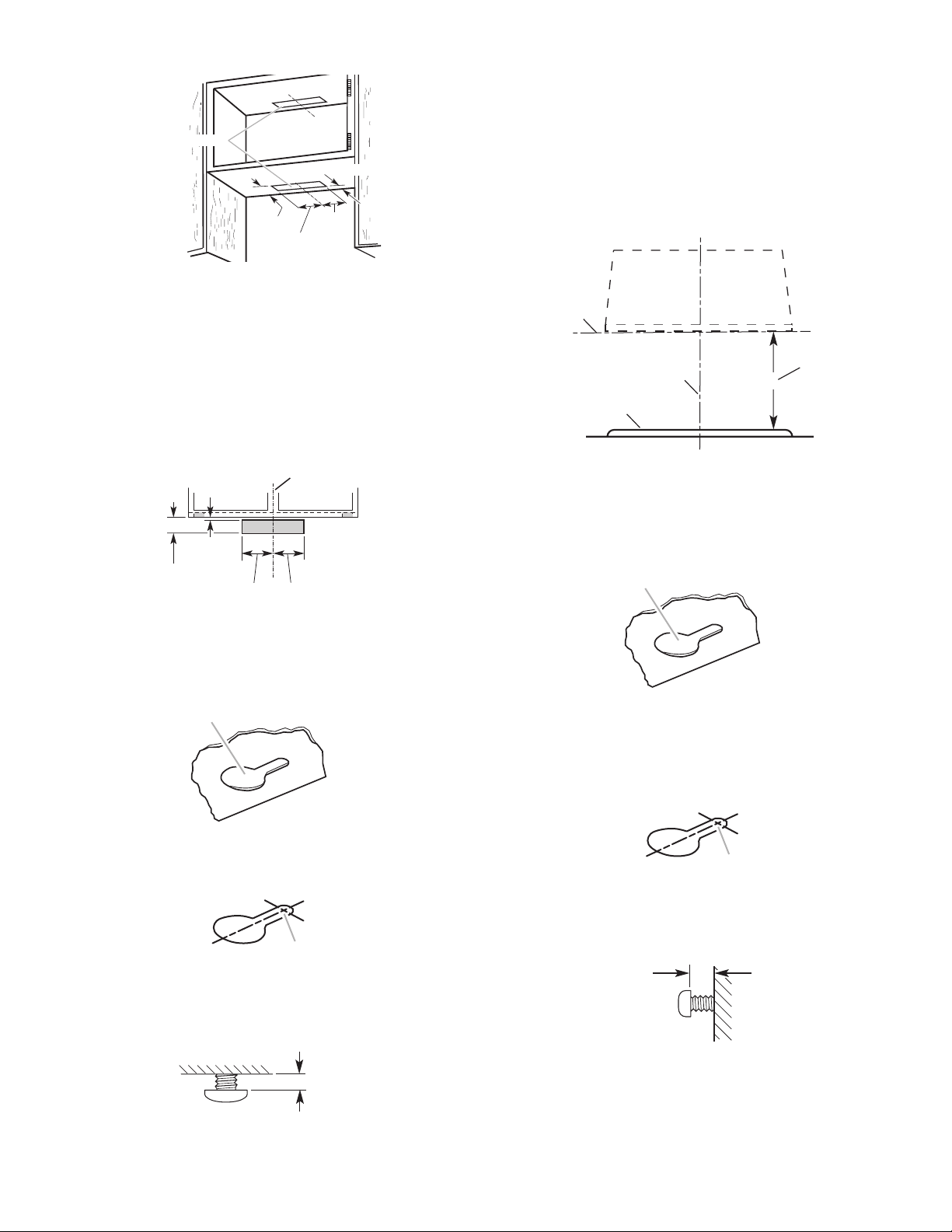
4. Repeat steps 1-3 for the underside of the top of the cabinet�
Cabinet cutouts
³⁄₈"
3 ⁷⁄₈"
Cabinet
front
(0.9 cm)
(9.8 cm)
5
¹⁄₄
"
(13.3 cm)
Centerline
5
¹⁄₄
"
(13.3 cm)
A
A
(6.4 mm)
A
A
A
*¹⁄₂" (1.3 cm)
*4¹⁄₂"
(11.4 cm)
*From wall, not cabinet frame
5¹/₄"
(13.3 cm)
5¹/₄"
(13.3 cm)
Wall Venting Under Cabinet
To make a 31/2" x 101/2" (8.9 cm x 26.7 cm) rectangle in
thewall:
1. Make two lines by measuring 3/8" (9�5 mm) and 37/8"
(9�8cm) down from underside of cabinet and mark on the
centerline on the back wall�
2. Mark lines 51/4" (13�3 cm) to the right and left of the
centerline on the wall�
Use saber or keyhole saw to cut a rectangular opening in the
wall for the vent�
For Wall Installations:
1. Determine and mark the centerline on the wall where the
canopy hood will be installed�
2. Select a mounting height between a minimum of 24"
(61�0cm) for electric cooking surfaces and 30" (76�2 cm) for
gas cooking surfaces� The suggested maximum height is 36"
(91�4 cm) above the range to the bottom of the hood� Mark a
horizontal reference line on the wall�
3. Using two or more people, center the hood on the vertical
centerline, then align the bottom of the hood with the
horizontal reference line marked on the wall�
B
D
A. Horizontal reference line
B. Vertical centerline
C. Mounting height
D. Cooking surface
C
X
3. Lift the range hood up under cabinet and determine nal
location by centering beneath cabinet� Mark on the
underside of cabinet the location of the four keyhole
mounting slots on the range hood� Set range hood aside on
a covered surface�
A. Keyhole slot
4. Use 1/8" (3�0 mm) drill bit and drill four pilot holes as
shown�
A. Drill pilot hole.
5. Install the 4 - 4�5 x 13 mm mounting screws in pilot
holes� Leave about 1/4" (6�4 cm) space between screw
heads and cabinet to slide range hood into place�
4. Mark centers of the fastener locations to the wall� Set range
hood aside on a covered surface�
A. Keyhole slot
IMPORTANT: All screws must be installed into wood� If there
is no wood to screw into, additional wall framing supports
may be required�
5. Drill 3/16" (4�8 mm) pilot holes at all locations where screws
are being installed into wood�
A. Drill pilot hole.
6. Install the 4 - 5 x 45 mm mounting screws� Leave a 1/4"
(6�4mm) gap between the wall and the back of the screw
head to slide range hood into place�
¹⁄₄"
(6.4 mm)
7. Determine and make all necessary cuts in the wall or ceiling
for the vent system� Install the vent system before installing
the hood� See the “Venting Requirements” section�
¹⁄₄"
9
Complete Preparation
A
B
B
D
E
1. Determine the required height for the home power supply
cable and drill a 11/4" (3�2 cm) hole at this location�
2. Run the home power supply cable according to the National
Electrical Code or CSA Standards and local codes and
ordinances� There must be enough 1/2" (12�7 mm) conduit
and wires from the fused disconnect (or circuit breaker) box
to make the connection in the hood’s electrical terminal box�
NOTE: Do not reconnect power until installation is complete�
3. Remove the grease lters� See the “Range Hood
Care”section�
4. Remove terminal box cover and set aside�
5. Remove knockout from the top of the vent hood and install a
UL Listed or CSA approved 1/2" (12�7 mm) strain relief�
Install Range Hood
1. Depending on your installation, remove either top or rear
rectangular vent knockout�
4. Using two or more people, lift the hood into nal position�
Feed enough electrical wire through the 1/2" (12�7 mm)
ULListed or CSA approved strain relief to make connections
in the terminal box� Tighten the strain relief screws�
5. Position the range hood so that the large end of the keyhole
slots are over the mounting screws� Then push the hood
toward the wall (for cabinet mounting) or allow the range
hood to slide down to the marked mounting height (for wall
mounting) so that the screws are in the neck of the slots�
Tighten the mounting screws, making sure the screws are
in the narrow neck of slots� (For wall mount, check that the
hood is level)�
6. Connect ventwork to hood� Seal joints with clamps to make
secure and airtight�
7. Check that back draft dampers work properly�
Make Electrical Connection
WARNING
Electrical Shock Hazard
Disconnect power before servicing.
Replace all parts and panels before operating.
Failure to do so can result in death or electrical shock.
A. Vent knockouts
2. Remove tape from damper ap�
NOTE: The 31/4" x 10" (8�3 x 25�4 cm) rectangular damper
can be installed up to 1" (2�5 cm) on either side of the hood
center to accommodate off center duct work
3. Attach the 31/4” x 10" (8�3 x 25�4 cm) rectangular vent
connector to the range hood using sheet metal screws�
A
C
D
E
C
A. Top venting
B. Sheet metal screws
C. Hinge pin
D. Vent knockouts
E. Rear venting
NOTE: If the wall cap is directly behind the 31/4" x 10" (8�3 x
25�4 cm) rectangular vent connector, check that the damper
and the wall cap do not interfere with each other� Remove
the damper from the 31/4" x 10" (8�3 x 25�4 cm) rectangular
vent connector if they interfere�
1. Disconnect power�
A
B
C
F
A. White wires
B. Black wires
C. UL Listed wire connector
D. Green (or bare) and yellow-green ground wire
E. Home power supply cable
F. UL Listed or CSA approved 1/2" (12.7 mm) strain relief
2. Use UL Listed wire connectors and connect white wires (A)
together�
3. Use UL Listed wire connectors and connect black wires (B)
together�
10
WARNING
B
C
5. Install terminal box cover�
6. Check that all light bulbs are secure in their sockets�
7. Reconnect power�
Install Vent Covers (Optional)
If you are installing an optional full width duct cover, follow the
instructions included with that product�
Electrical Shock Hazard
Electrically ground blower.
Connect ground wire to green and yellow ground wire
in terminal box.
Failure to do so can result in death or electrical shock.
4. Connect green (or bare) ground wire from home power
supply to yellow-green ground wire (C) in terminal box using
UL Listed wire connectors�
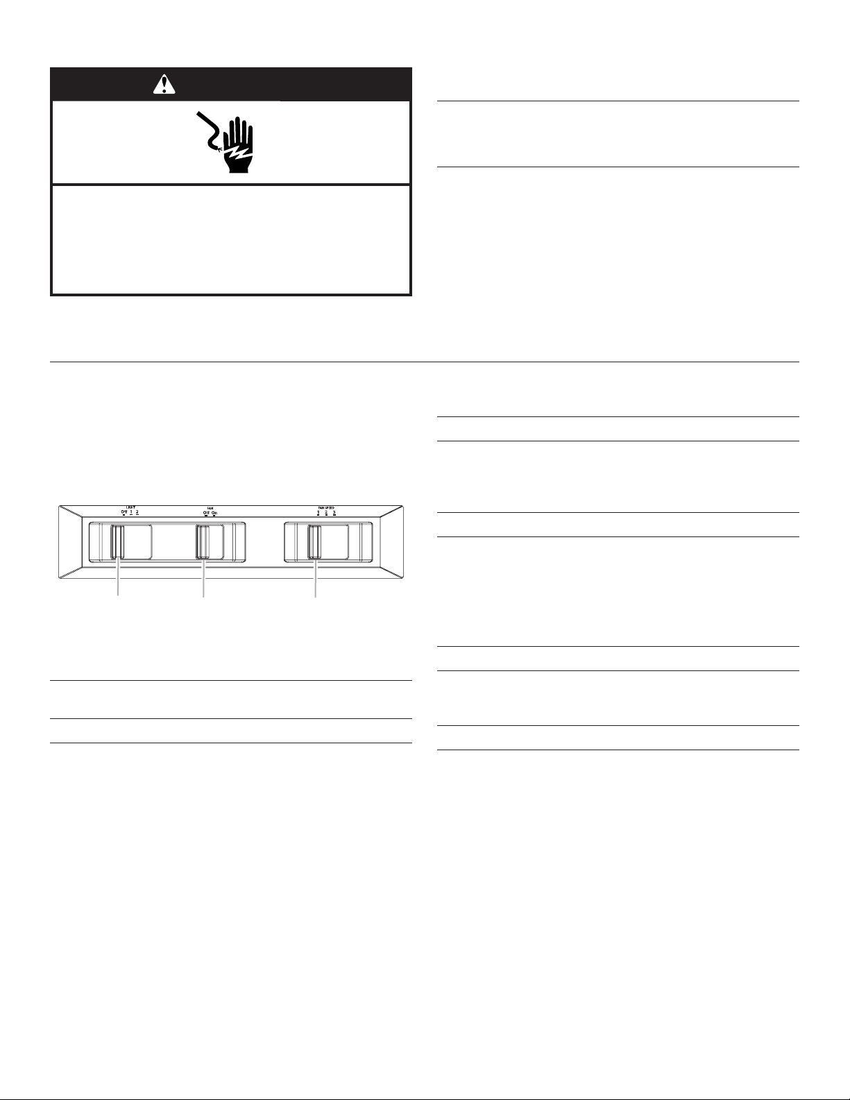
RANGE HOOD USE
The range hood is designed to remove smoke, cooking vapors,
and odors from the cooktop area� For best results, start the hood
before cooking and allow it to operate several minutes after
the cooking is complete to clear all smoke and odors from the
kitchen�
The hood controls are located on the underside of the
rangehood�
A
A. Light control
B. Blower control
C. Fan speed control
Complete Installation
1. Install metal grease lters� See the “Range Hood
Care”section�
2. Check the operation of the range hood blower and light� See
the “Range Hood Use” section�
NOTE: To get the most efcient use from your new range
hood, read the “Range Hood Use” section�
Operating the fan
1. Move the fan switch to the on position to turn the fan on� The
fan will begin operating at the speed set on the fan speed
switch�
2. Move the fan switch to the Off position to turn the fan off�
Auto on fan
The range hood is equipped with a sensor to automatically turn
on the fan when excessive heat is detected in the control area�
When the fan switch is in the off position, this sensor will turn the
fan to high speed when necessary� When the heat decreases,
the fan will turn off�
When the fan switch is in the on position, the heat sensor is not
active, and the range hood functions normally�
Adjusting the fan
Range Hood Controls
Operating the light
1. Move the light switch to the “1” position to turn range hood
light to night light setting�
2. Move the light switch to the “2” position to turn range hood
light to full light setting�
3. Move the light switch to the “Off” position to turn range hood
light off�
The fan has three speed controls� Move the fan speed switch to
“1” position for low speed, “2” position for medium speed, or “3”
position for high speed�
Thermal protector
The range hood is equipped with a thermal protector to avoid
overheating conditions� If the range hood shuts off while in use,
move fan slider switch to off to turn off the range hood� Wait
approximately 60 minutes, then move slider to on to restart the
range hood�
11
RANGE HOOD CARE
Cleaning
IMPORTANT: Clean the hood and grease lters frequently
according to the following instructions� Replace grease lters
before operating hood�
Exterior Surfaces:
To avoid damage to the exterior surface, do not use steel wool
or soap-lled scouring pads�
Always wipe dry to avoid water marks�
Cleaning Method:
■ Liquid detergent soap and water, or all-purpose cleanser�
■ Wipe with damp soft cloth or nonabrasive sponge, then rinse
with clean water and wipe dry�
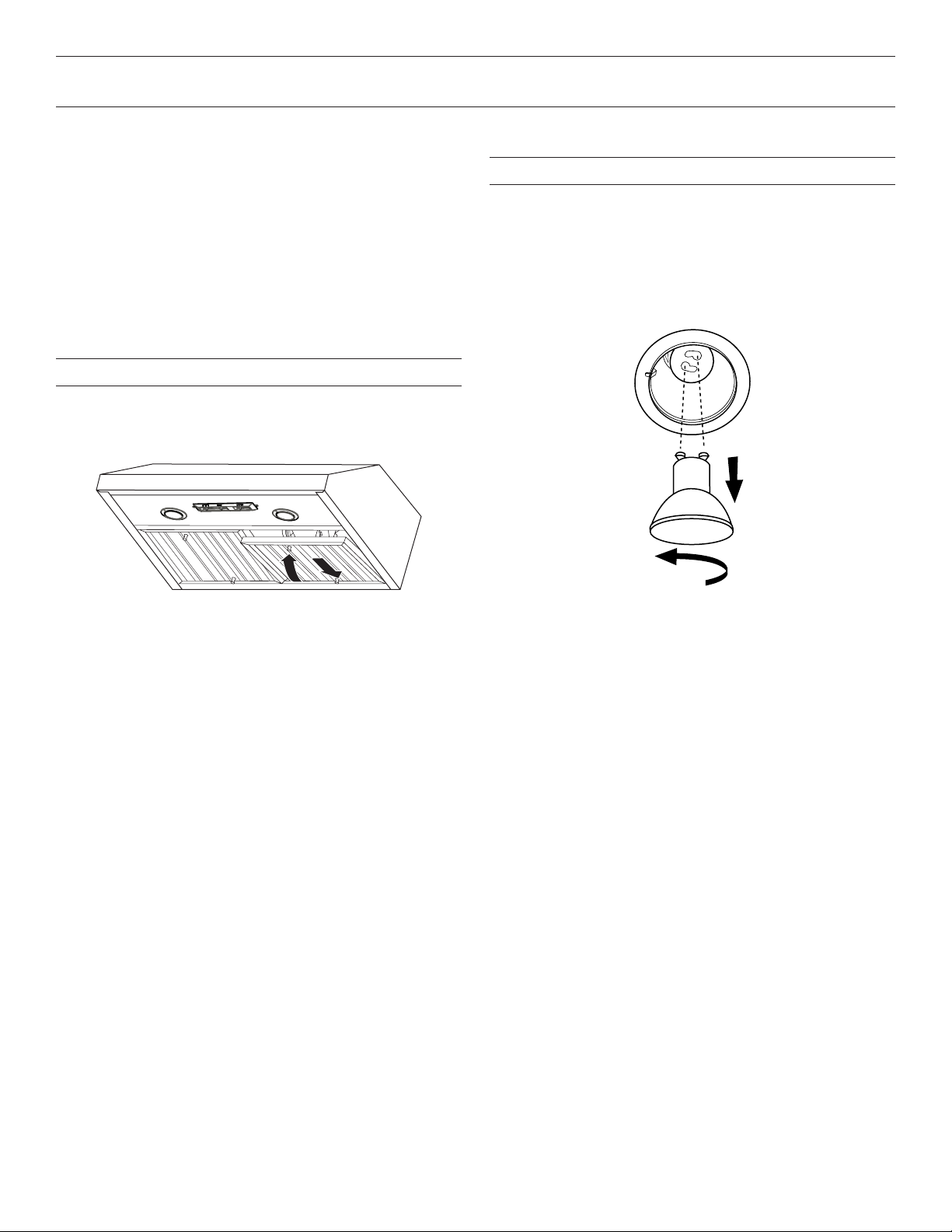
Metal Grease Filter
To Remove Metal Grease Filters:
1. Use two hands to remove the metal grease lters� Grasp
lter handles, push toward the rear of the range hood, and
pull down on the front handle to remove�
Replacing a Halogen Lamp
Turn off the range hood and allow the halogen lamp to cool� To
avoid damage or decreasing the life of the new lamp, do not
touch lamp with bare ngers� Replace lamp, using tissue or
wearing cotton gloves to handle lamp�
If new lamps do not operate, make sure the lamps are inserted
correctly before calling service�
1. Disconnect power�
2. Push up on the lens and turn it counterclockwise�
2. Repeat for each grease lter�
3. Wash metal grease lters as needed in a dishwasher or hand
wash in a hot detergent solution to clean�
To Reinstall Metal Grease Filters:
1. Grasp lter handles and place rear of lter into rear track�
2. Push down on the rear handle and set the front of the grease
lter into the front track to secure�
3. Repeat for each lter�
3. Remove the lamp and replace it with a 120-volt, 50-watt
maximum halogen lamp with a GU10 base� Turn it clockwise
to lock it into place�
4. Repeat steps 2-3 for the other lamp if needed�
5. Reconnect power�
12
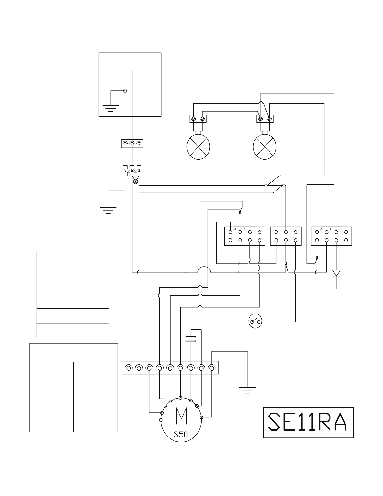
WIRING DIAGRAM
Junction Box
N
L
GND
W
BK
Y/G
Y
W
Y
W
W
Motor Resistance
(Ohms)
Blue - Red
Blue - Gray
Blue - Black
Blue - White
Room Temp.
Motor
Characteristics
Power Supply
18
14.3
9.8 (max)
21.6 (min)
41˚F (23˚C)
120 VAC
BU
BK
BU
BK
GY
Speed 3
Speed 2
Speed 1
W
Y
25uF
BR
BR
BK
BR
Fan Speed
GY
R R
BR
Temperature
Y/G
R
Sensor
W
Off
On
Fan
W
BK
BR
BR
Y
Off
Light
Y
BK
Y
Frequency
Power Absorption
Current
60 HZ
420 W
3.7A
BU
GY
BK
R
Y
W
BR
Y/G
13

ASSISTANCE OR SERVICE
When calling for assistance or service, please know the
purchase date and the complete model and serial number of
your appliance� This information will help us to better respond to
your request�
If you need replacement parts
If you need to order replacement parts, we recommend that
you use only factory specied parts� Factory specied parts will
t right and work right because they are made with the same
precision used to build every new appliance� To locate factory
specied replacement parts in your area, call us or your nearest
designated service center�
In the U.S.A.
Ifyou have any problems or questions, call KitchenAid at
1-800-422-1230�
Our consultants provide assistance with:
■ Scheduling of service� KitchenAid appliances designated
service technicians are trained to fulll the product warranty
and provide after-warranty service anywhere in the United
States�
■ Features and specications on our full line of appliances�
■ Referrals to local KitchenAid appliance dealers�
■ Installation information�
■ Use and maintenance procedures�
■ Accessory and repair parts sales�
■ Specialized customer assistance (Spanish speaking, hearing
impaired, limited vision, etc�)�
Accessories
Full Width Chimney Cover
Order Part Number W10272079 for 30” (76�2 cm) model
Order Part Number W10272080 for 36” (91�4 cm) model
In Canada
Ifyou have any problems or questions, call KitchenAid at
1-800-807-6777�
Our consultants provide assistance with:
■ Scheduling of service� KitchenAid appliances designated
service technicians are trained to fulll the product warranty
and provide after-warranty service anywhere in Canada�
■ Features and specications on our full line of appliances�
■ Referrals to local KitchenAid appliance dealers�
■ Use and maintenance procedures�
■ Accessory and repair parts sales�
For further assistance:
If you need further assistance, you can write to KitchenAid with
any questions or concerns at:
KitchenAid Brand Home Appliances
Customer eXperience Centre
200 - 6750 Century Ave�
Mississauga, Ontario L5N 0B7
Please include a daytime phone number in your correspondence�
For further assistance:
If you need further assistance, you can write to KitchenAid with
any questions or concerns at:
KitchenAid Brand Home Appliances
Customer eXperience Center
553 Benson Road
Benton Harbor, MI 49022-2692
Please include a daytime phone number in your correspondence�
14
 Loading...