

KitchenAid KXD4736Y Guide
30" (76.2 cm) and 36" (91.4 cm) Retractable (Pop-Up)
Downdraft Vent System
Because Whirlpool Corporation policy includes a continuous commitment to improve
our products, we reserve the right to change materials and specifications without notice.
Dimensions are for planning purposes only. For complete details, see Installation
Instructions packed with product. Specifications subject to change without notice.
Ref. W10342489D
1/31/2012
Page 1 of 3
PRODUCT MODEL NUMBERS
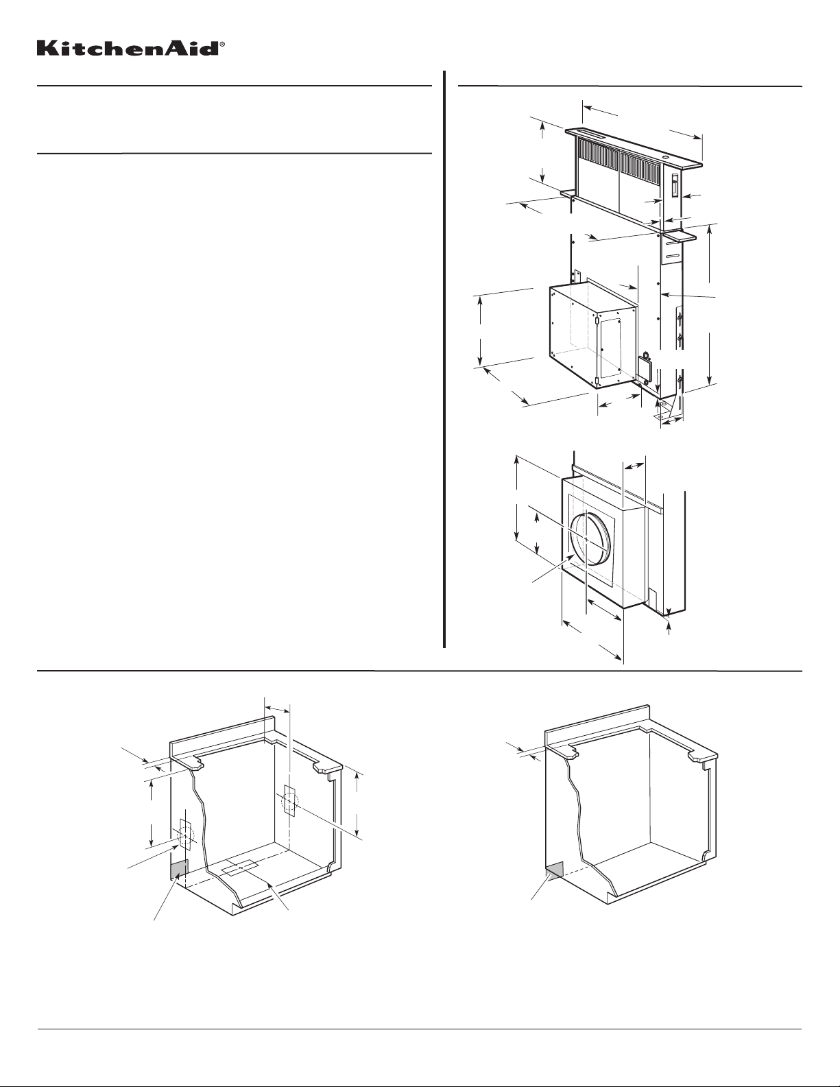
PRODUCT DIMENSIONS
KXD4630Y KXD4636Y KXD4736Y
Electrical
A 120 Volt, 60 Hz., AC only 15-amp fused, electrical circuit is required.
LOCATION REQUIREMENTS
NOTE: Downdraft vent is installed directly behind the cooktop. Install the
downdraft vent first, then install the cooktop.
IMPORTANT: Observe all governing codes and ordinances.
●
Have a qualified technician install the downdraft vent. It is the installer’s
responsibility to comply with installation clearances specified on the
model/serial rating plate. The model/serial rating plate is located on the front of
the downdraft vent above the terminal box cover.
●
Downdraft vent location should be away from strong draft areas, such as
windows, doors, and strong heating vents or fans.
●
Cabinet opening dimensions that are shown must be used. Given dimensions
provide minimum clearance.
●
Consult the cooktop manufacturer installation instructions before making any
cutouts.
Check that the downdraft vent and cooktop location will clear the
cabinet walls, backsplash, and rear wall studs inside the cabinet.
Check for the minimum distance between the front edge of the
countertop and the front edge of the cooktop. The minimum horizontal
distance between the overhead cabinets is the same as the width of the
installed downdraft vent.
●
All openings in ceiling and wall where the downdraft vent will be installed must
be sealed.
●
Grounded electrical outlet is required. See “Electrical Requirements” section.
●
When installing the downdraft vent, the cabinet drawer will need to be removed
and the drawer front installed permanently to the cabinet.
Cabinet Construction:
Downdraft vent is designed for use in a cabinet with a depth of 24" (61 cm).
Some installations require a countertop deeper than 25" (63.5 cm). See the
Countertop Cutout Dimensions section.
The maximum depth of the overhead cabinet is 13" (33 cm). Overhead cabinets
installed at either side of the downdraft vent must be 18" (45.7 cm) above the
cooking surface.
For Mobile Home Installations
The installation of this range hood must conform to the Manufactured Home
Construction Safety Standards, Title 24 CFR, Part 328 (formerly the Federal
Standard for Mobile Home Construction and Safety, title 24, HUD, Part 280) or
when such standard is not applicable, the standard for Manufactured Home
Installation 1982 (Manufactured Home Sites, Communities and Setups) ANSI
A225.1/NFPA 501A*, or latest edition, or with local codes.
ledom rotom rewolb detnuom-roiretxE
ledom rotom rewolb detnuom-roiretnI
A= ¹⁄₂" (12.7 mm)
minimum
21⁵⁄₁₆"
(54.1 cm)
Cutouts are
for 3¹⁄₄" x 10"
(8.3 x 25.4 cm)
rectangular or 6"
(15.2 cm) round
vent system.
Centerline of cooktop cutout
21⁵⁄₁₆"
(54.1 cm)
Locate power
supply junction
box at lower
left hand
rear corner
of the cabinet.
10" (25.4 cm)
¹⁄₂" (12.7 mm)
minimum
Locate power
supply junction
box at lower
left hand
rear corner
of the cabinet.
CABINET DIMENSIONS
NOTES:
●
See cooktop manufacturer’s instructions for cooktop cutout depth and
width.
●
Use dimensions for vent system cutout location that applies to your
installation.
●
Interior mounted blower systems connect with 3¹⁄₄" x 10" (8.3 x 25.4 cm)
rectangular or 6" (15.2 cm) round vent system. The cutout locations for
this vent system will depend on your specific installation.
NOTES:
●
See cooktop manufacturer’s instructions for cooktop cutout depth and
width.
●
Exterior-mounted blower systems connect with 10" (25.4 cm) round vent.
The cutout locations for this vent system will depend upon your specific
installation.
Models with interior-mounted blower motor
13¹⁄₂" (34.3 cm)
retractable
vent height
27" (68.6 cm) for 30" (76.2 cm) vent
33" (83.8 cm) for 36" (91.4 cm) vent
13¹⁄₈" (33.4 cm)
16¹⁄₂" (42.0 cm)
Models with exterior-mounted blower motor
13¹⁄₈" (33.4 cm)
6⁹⁄₁₆"
(16.7 cm)
10" (25.4 cm)
diameter
vent collar
16¹⁄₂" (42.0 cm)
(25.4 cm)
8¹⁄₄"
(21.0 cm)
Top trim widths:
30" (76.2 cm)
36" (91.4 cm)
10"
4³⁄₄" (12.1 cm)
³⁄₄
(1.9 cm)
2¹⁄₈" (5.4 cm)
³⁄₄" (1.9 cm)
1¹⁄₂" (3.8 cm)
³⁄₈" (0.95 cm)
5¹⁄₄"(13.3 cm)
for 30" (76.2 cm) vent
8¹⁄₄"(21.0 cm)
for 36" (91.4 cm) vent
28¹⁄₂"
(72.4 cm)
Because Whirlpool Corporation policy includes a continuous commitment to improve
our products, we reserve the right to change materials and specifications without notice.
Dimensions are for planning purposes only. For complete details, see Installation
Instructions packed with product. Specifications subject to change without notice.
Ref. W10342489D
1/31/2012
Page 2 of 3
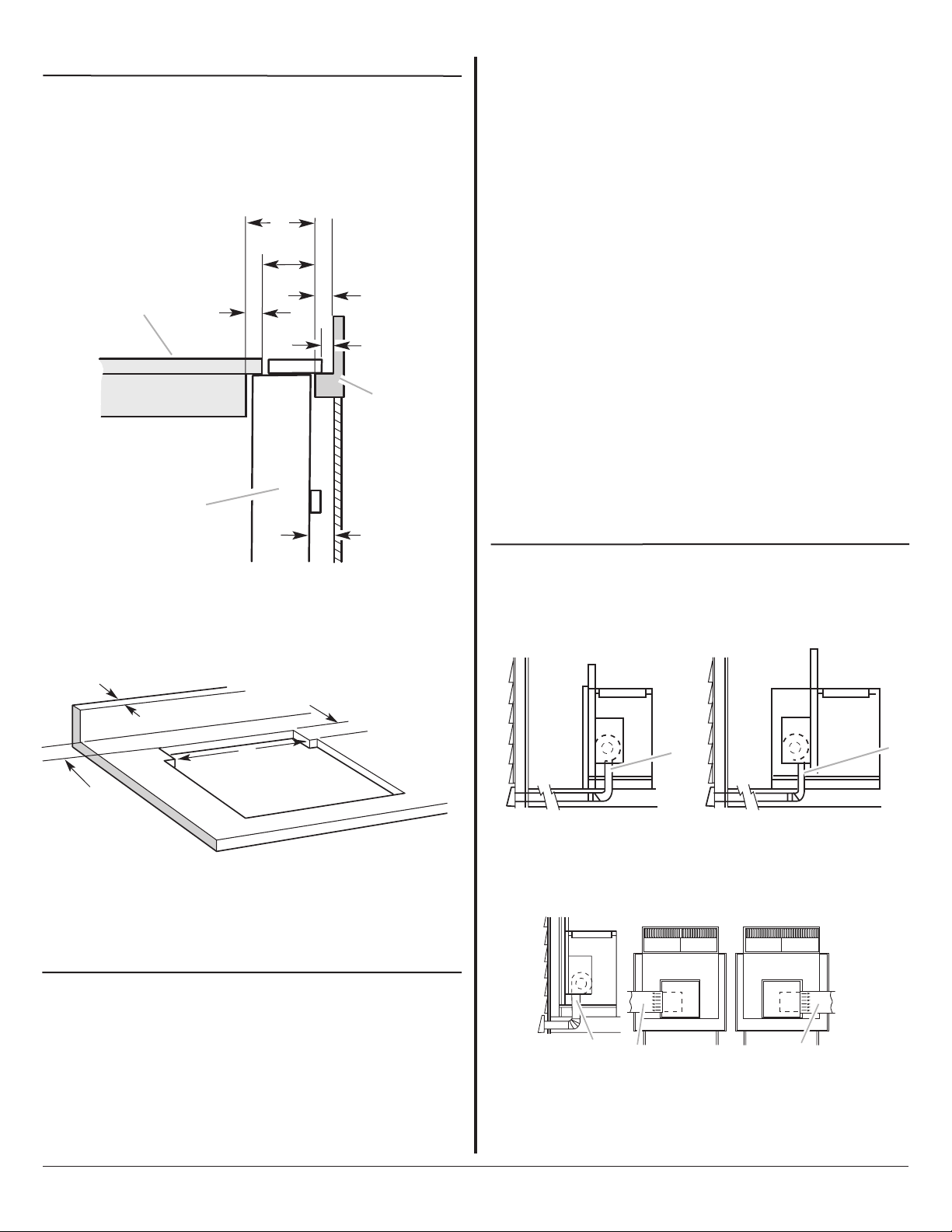
VENTING METHODS - INTERIOR MOUNTED VENT MOTOR ONLY
Determine which venting method is best for your application. Vent system
can terminate through either the wall or floor.
A
NOTE: For island locations, the blower motor can be mounted for right,
left, or rear venting if needed for your application. Most island applications
would still require the venting to be directed down through the floor.
A
H
COUNTERTOP CUTOUT DIMENSIONS
IMPORTANT: Countertops with a bull-nosed front edge are not
recommended for these installations.
●
Some models require a countertop deeper than 25" (63.5 cm); see the
following Countertop Cutout Dimensions section.
●
To avoid mistakes, it is recommended that the cooktop and vent cutouts
be drawn on the countertop before making any cutouts.
●
See Cooktop Installation Instructions for complete cutout dimensions,
location dimensions and installation details.
VENTING REQUIREMENTS
IMPORTANT: Make sure there is proper clearance within the wall or floor
before making exhaust vent cutouts.
●
Use heavy (rigid) metal vent.
●
Venting system must terminate to the outside.
●
Do not terminate the vent system in an attic or other enclosed area.
●
Do not use 4" (10.2 cm) laundry-type wall caps.
●
Do not install 2 elbows together.
●
Do not use plastic or metal foil vent.
●
The length of vent system and number of elbows should be kept to a
minimum to provide efficient performance.
●
Use no more than three 90° elbows.
●
Make sure there is a minimum of 24" (61 cm) of straight vent between
the elbows if more than one elbow is used.
●
Use clamps or duct tape to seal all joints in the vent system.
●
Use caulking tape to seal the exterior wall or floor opening around cap.
●
Do not cut joist or stud. If vent cutout falls over a joist or stud, a
supporting frame must be constructed.
Flexible metal vent is not recommended. If it is used, calculate each foot of
flexible vent as 2 ft (0.6 m) of rigid metal vent.
Flexible elbows count twice as much as standard elbows.
Recommended Vent System Length
For either interior-mounted or exterior-mounted blower installations, the
vent system length should not exceed the maximum lengths listed in the
Maximum Length of Vent System chart. See “Calculating Vent System
Length” in the “Venting Methods” section in the Installation Instructions
for the interior- or exterior-mounted vent motor.
Cold Weather Installations
An additional back draft damper should be installed to minimize backward
cold air flow and a thermal break should be installed to minimize
conduction of outside temperatures as part of the vent system. The
damper should be on the cold air side of the thermal break.
The break should be as close as possible to where the vent system enters
the heated portion of the house.
Makeup Air
Local building codes may require the use of makeup air systems when
using ventilation systems greater than specified CFM of air movement. The
specified CFM varies from locale to locale. Consult your HVAC professional
for specific requirements in your area.
D
E
F
B
C
G
A
.Downdraft vent
B. Cooktop
C. Measurement of cooktop rear
overhang.
D. D = Measurement of cooktop rear
overhang (C) + 1¹³⁄₁₆" [46.2 mm] (E)
B
A
A. ½" (12.7 mm) minimum to
backsplash or rear wall
B. ³⁄₄" (19.1 mm) maximum
backsplash depth
I
E. 1¹³⁄₁₆" (46.2 mm)
F. ½" (12.7 mm) minimum
G. ¼" (6.4 mm) minimum
H. Countertop and backsplash
I. ½" (12.7 mm) minimum
D
C
C. 27¹⁄₂" (69.9 cm) on 30" (76.2 cm)
models
¹⁄₂" (85.9 cm) on 36" (91.4 cm)
33
models
D. D = Measurement of cooktop rear
overhang + 1
¹³⁄₁₆" (46.2 mm)
Island location
Front (standard) mounted
blower motor
Rear mounted blower
motor
A
A. Down vent
B
A
A. Down vent
B. Left vent
C. Right vent
C
 Loading...