

KitchenAid KWCU565WSS0, KWCU505WSS0 Owner’s Manual
I_i|chen_kid ®
30" (76.2 CM) AND 36" (91.4 CM) WALL-MOUNT
CANOPY HOOD
For questions about features, operation/performance, parts, accessories or service, call: 1-800-422-1230
In Canada, for assistance, installation and service, call: 1-800-807-6777
or visit our website at www,kitchenaid,com
or visit our website at www,kitchenaid,ca
HO IIE DE CUISINIERE POUR MONTAGE
MURAL 30" (76,2 CM) ET 36" (91,4 CM)
Au Canada, pourassistance,installationou servicecomposez le1-800-807-6777
Table of Contents/Table des matieres ............................................................................. 2
ou visiteznotresiteweb a www,Mtchenaid,ca
IMPORTANT: READ AND SAVE THESE INSTRUCTIONS.
FOR RESIDENTIAL USE ONLY.
iMPORTANT : MRE ET CONSERVER CES iNSTRUCTiONS.
POUR UTILISATION Rf-=SIDENTIELLE UNIQUEMENT.
W10268948C
TABLEOF CONTENTS
TABLEDES MATIERES
RANGE HOOD SAFETY ................................................................. 3
INSTALLATION REQUIREMENTS ................................................ 5
Tools and Parts ............................................................................ 5
Location Requirements ................................................................ 5
Venting Requirements .................................................................. 6
Electrical Requirements ............................................................... 7
INSTALLATION INSTRUCTIONS .................................................. 8
Prepare Location .......................................................................... 8
Install Range Hood ....................................................................... 9
Make Electrical Connection ......................................................... 9
Install Chimney Covers .............................................................. 10
Complete Installation ................................................................. 11
RANGE HOOD USE ...................................................................... 11
RANGE HOOD CARE ................................................................... 12
Cleaning ...................................................................................... 12
WIRING DIAGRAM ...................................................................... 13
ASSISTANCE OR SERVICE ......................................................... 14
In the U.S.A................................................................................ 14
In Canada ................................................................................... 14
Accessories ................................................................................ 14
WAR RANTY .................................................................................. 15
SI_CURITI_ DE LA HOTTE DE CUlSINIERE ............................... 17
EXIGENCES D'INSTALLATION ................................................... 19
Outillage et pieces ...................................................................... 19
Exigences d'emplacement ......................................................... 19
Exigences concernant I'evacuation ........................................... 21
Specifications electriques .......................................................... 22
INSTRUCTIONS D'INSTALLATION ............................................. 23
Preparation de I'emplacement ................................................... 23
Installation de la hotte ................................................................ 24
Raccordement electrique ........................................................... 25
Installation du cache-cheminee ................................................. 26
Achever I'installation .................................................................. 26
UTILISATION DE LA HOTTE ....................................................... 27
ENTRETIEN DE LA Ho'n'E .......................................................... 27
Nettoyage ................................................................................... 27
SCHI_MA DE C.&,BLAGE............................................................... 29
ASSISTANCE OU SERVICE ......................................................... 30
Accessoires ................................................................................ 30
GARANTIE ..................................................................................... 31
2
RANGE HOOD SAFETY
Your safety and the safety of others are very important.
We have provided many important safety messages in this manual and on your appliance. Always read and obey all safety
messages.
This is the safety alert symbol.
This symbol alerts you to potential hazards that can kill or hurt you and others.
All safety messages will follow the safety alert symbol and either the word "DANGER" or "WARNING."
These words mean:
You can be killed or seriously injured if you don't immediately
follow instructions.
You can be killed or seriously injured if you don't follow
instructions.
All safety messages will tell you what the potential hazard is, tell you how to reduce the chance of injury, and tell you what can
happen if the instructions are not followed.
iMPORTANT SAFETY iNSTRUCTiONS
WARNING: TO REDUCE THE RISK OF FIRE, ELECTRIC
SHOCK, OR INJURY TO PERSONS, OBSERVE THE
FOLLOWING:
[] Use this unit only in the manner intended by the
manufacturer. If you have questions, contact the
manufacturer.
[] Before servicing or cleaning the unit, switch power off at
service panel and lock the service disconnecting means to
prevent power from being switched on accidentally. When
the service disconnecting means cannot be locked,
securely fasten a prominent warning device, such as a tag,
to the service panel.
[] Installation work and electrical wiring must be done by
qualified person(s) in accordance with all applicable codes
and standards, including fire-rated construction.
[] Sufficient air is needed for proper combustion and
exhausting of gases through the flue (chimney) of fuel
burning equipment to prevent backdrafting. Follow the
heating equipment manufacturer's guideline and safety
standards such as those published by the National Fire
Protection Association (NFPA), the American Society for
Heating, Refrigeration and Air Conditioning Engineers
(ASHRAE), and the local code authorities.
[] When cutting or drilling into wall or ceiling; do not damage
electrical wiring and other utilities.
[] Ducted fans must always be vented outdoors.
CAUTION: For general ventilating use only. Do not use
to exhaust hazardous or explosive materials and vapors.
CAUTION: To reduce risk of fire and to properly exhaust
air, be sure to duct air outside - do not vent exhaust air into
spaces within walls or ceilings, attics or into crawl spaces,
or garages.
WARNING: TO REDUCE THE RISK OF FIRE, USE ONLY
METAL DUCTWORK.
WARNING: TO REDUCE THE RISK OF A RANGE TOP
GREASE FIRE:
[] Never leave surface units unattended at high settings.
Boilovers cause smoking and greasy spillovers that may
ignite. Heat oils slowly on low or medium settings.
[] Always turn hood ON when cooking at high heat or when
flambeing food (i.e. Crepes Suzette, Cherries Jubilee,
Peppercorn Beef Flamb6).
[] Clean ventilating fans frequently. Grease should not be
allowed to accumulate on fan or filter.
[] Use proper pan size. Always use cookware appropriate for
the size of the surface element.
WARNING: TO REDUCE THE RISK OF INJURY TO
PERSONS IN THE EVENT OF A RANGE TOP GREASE
FIRE, OBSERVE THE FOLLOWING: a
[] SMOTHER FLAMES with a close fitting lid, cookie sheet, or
metal tray, then turn off the burner. BE CAREFUL TO
PREVENT BURNS. If the flames do not go out
immediately, EVACUATE AND CALL THE FIRE
DEPARTMENT.
[] NEVER PICK UP A FLAMING PAN - you may be burned.
[] DO NOT USE WATER, including wet dishcloths or towels -
a violent steam explosion will result.
[] Use an extinguisher ONLY if:
- You know you have a class ABC extinguisher, and you
already know how to operate it.
- The fire is small and contained inthe area where it
started.
- The fire department is being called.
- You can fight the fire with your back to an exit.
aBased on "Kitchen Fire Safety Tips" published by NFPA.
[] WARNING: To reduce the risk of fire or electrical shock,
do not use this fan with any solid-state speed control
device.
READ AND SAVE THESE iNSTRUCTiONS
INSTALLATION REQUIREMENTS
_?' i_: _ _._1:_
Gather the required tools and parts before starting installation.
Read and follow the instructions provided with any tools listed
here.
Tools needed
• Level
• Drill
• 11¼'' (3 cm) drill bit
• 3/32"(2.4 mm) drill bit
• 1/8"(3 mm) drill bit
• Pencil
• Wire stripper or utility knife
• Tape measure or ruler
• Pliers
• Caulking gun and weatherproof caulking compound
• Vent clamps
• Jigsaw or keyhole saw
• Flat-blade screwdriver
• Metal snips
• Phillips screwdriver
• Scissors
Parts needed
• Home power supply cable
• 1 - 1/2"(12.7 ram) UL listed or CSA approved strain relief
• 2 UL listed wire connectors
For vented installations, you will also need:
• 1 wall or roof cap
• Metal vent system
For non-vented (recirculating) installations, you will also
need:
• Recirculation Kit Part Number W10271501 for non-vented
(recirculating) installations only. See "Assistance or Service"
section to order.
Parts supplied
Remove parts from packages. Check that all parts are included.
• 2 metal grease filters for 30" (76.2 cm) models
3 metal grease filters for 36" (91.4 cm) models
• 6- flat head screws
• 2 - chimney mounting brackets
• 6 - #10 Phillips head mounting screws
• Upper chimney cover
• Lower chimney cover
• Damper
IMPORTANT: Observe all governing codes and ordinances.
Have a qualified technician install the range hood. It is the
installer's responsibility to comply with installation clearances
specified on the model/serial rating plate. The model/serial rating
plate is located inside the range hood on the rear wall of the
range hood.
Canopy range hood location should be away from strong draft
areas, such as windows, doors and strong heating vents.
Cabinet opening dimensions that are shown must be used. Given
dimensions provide minimum clearance.
Grounded electrical outlet is required. See "Electrical
Requirements" section.
The canopy range hood is factory set for venting through the roof
or through the wall. For non-vented (recirculating) Installation see
"Non-vented (recirculating) Installations" in "Prepare Location"
section. Recirculation Kit Part Number W10271501 is available
from your dealer or an authorized parts distributor.
All openings in ceiling and wall where canopy range hood will be
installed must be sealed.
For Mobile Home Installations
The installation of this range hood must conform to the
Manufactured Home Construction Safety Standards, Title 24
CFR, Part 328 (formerly the Federal Standard for Mobile Home
Construction and Safety, Title 24, HUD, Part 280) or when such
standard is not applicable, the standard for Manufactured Home
Installation 1982 (Manufactured Home Sites, Communities and
Setups) ANSI A225.1/NFPA 501A*, or latest edition, or with local
codes.
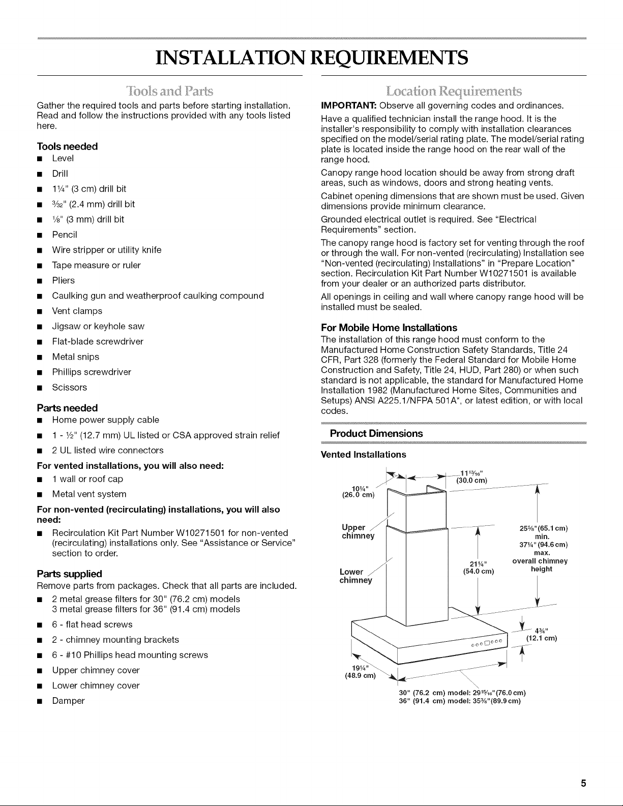
Product Dimensions
Vented Installations
10W' J
(26.0 cm)
Upper
chimney
Lower
chimney
30" (76.2 crn) model: 29_%d'(76.0crn)
36" (91.4 crn) model: 35s/8"(89.9crn)
(30.0 crn)
25%" (65.1 crn)
371A" (94.6 crn)
21W' overall chimney
(54.0 cm) height
rnin.
max.
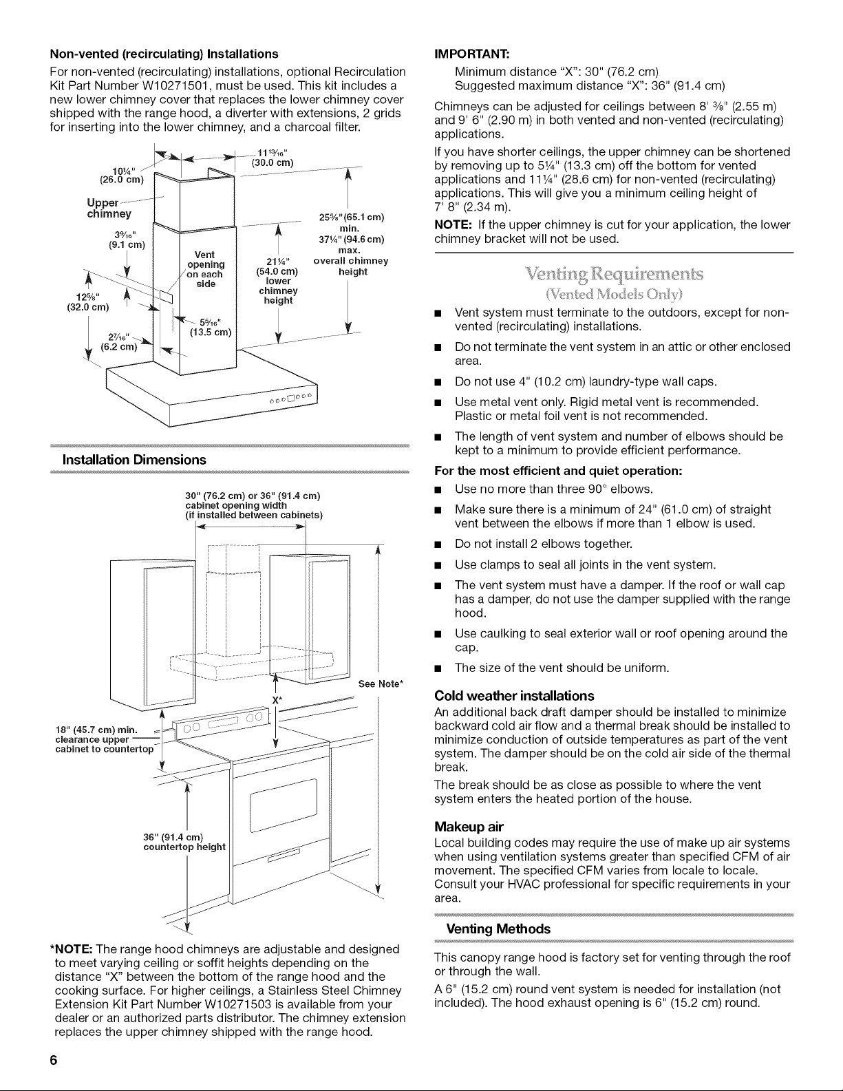
Non-vented (recirculating) Installations
For non-vented (recirculating) installations, optional Recirculation
Kit Part Number W10271501, must be used. This kit includes a
new lower chimney cover that replaces the lower chimney cover
shipped with the range hood, a diverter with extensions, 2 grids
for inserting into the lower chimney, and a charcoal filter.
10W'
(26.0 cm) ..........................................
(30.0 cm)
u
chimney
39/16"
(9.1 cm)
125/8"
(32.0 cm)
25%"(65.1 cm)
rain.
371A" (94.6 cm)
max.
overall chimney
height
Installation Dimensions
30" (76.2 cm) or 36" (91.4 cm)
cabinet opening width
if installed between cabinets)
i
See Note*
18" (45.7 cm) rain.
clearance upper --
cabinet to countertop
IM PORTANT:
Minimum distance "X": 30" (76.2 cm)
Suggested maximum distance "X": 36" (91.4 cm)
Chimneys can be adjusted for ceilings between 8' 3/8"(2.55 m)
and 9' 6" (2.90 m) in both vented and non-vented (recirculating)
applications.
If you have shorter ceilings, the upper chimney can be shortened
by removing up to 51¼'' (13.3 cm) off the bottom for vented
applications and 111¼"(28.6 cm) for non-vented (recirculating)
applications. This will give you a minimum ceiling height of
7' 8" (2.34 m).
NOTE: If the upper chimney is cut for your application, the lower
chimney bracket will not be used.
• Vent system must terminate to the outdoors, except for non-
vented (recirculating) installations.
• Do not terminate the vent system in an attic or other enclosed
area.
• Do not use 4" (10.2 cm) laundry-type wall caps.
• Use metal vent only. Rigid metal vent is recommended.
Plastic or metal foil vent is not recommended.
• The length of vent system and number of elbows should be
kept to a minimum to provide efficient performance.
For the most efficient and quiet operation:
• Use no more than three 90° elbows.
• Make sure there is a minimum of 24" (61.0 cm) of straight
vent between the elbows if more than 1 elbow is used.
• Do not install 2 elbows together.
• Use clamps to seal all joints in the vent system.
• The vent system must have a damper. If the roof or wall cap
has a damper, do not use the damper supplied with the range
hood.
• Use caulking to seal exterior wall or roof opening around the
cap.
• The size of the vent should be uniform.
Cold weather installations
An additional back draft damper should be installed to minimize
backward cold air flow and a thermal break should be installed to
minimize conduction of outside temperatures as part of the vent
system. The damper should be on the cold air side of the thermal
break.
The break should be as close as possible to where the vent
system enters the heated portion of the house.
36" (91.4 cm)
countertop height
*NOTE: The range hood chimneys are adjustable and designed
to meet varying ceiling or soffit heights depending on the
distance "X" between the bottom of the range hood and the
cooking surface. For higher ceilings, a Stainless Steel Chimney
Extension Kit Part Number W10271503 is available from your
dealer or an authorized parts distributor. The chimney extension
replaces the upper chimney shipped with the range hood.
6
Makeup air
Local building codes may require the use of make up air systems
when using ventilation systems greater than specified CFM of air
movement. The specified CFM varies from locale to locale.
Consult your HVAC professional for specific requirements in your
area.
Venting Methods
This canopy range hood is factory set for venting through the roof
or through the wall.
A 6" (15.2 cm) round vent system is needed for installation (not
included). The hood exhaust opening is 6" (15.2 cm) round.
NOTE: Flexible vent is not recommended. Flexible vent creates
back pressure and air turbulence that greatly reduce
performance.
Vent system can terminate either through the roof or wall. To vent
through a wall, a 90° elbow is needed.
Rear discharge
A 90°elbow may be installed immediately above the hood.
For non-vented (recirculating) installations
If it is not possible to vent cooking fumes and vapors to the
outside, the hood can be used in the non-vented (recirculating)
version, fitting an activated carbon filter and the diverter. Fumes
and vapors are recycled through the top grille.
NOTE: Non-vented (recirculating) installation is not allowed over
cooktops with BTU ratings of 60,000 or higher.
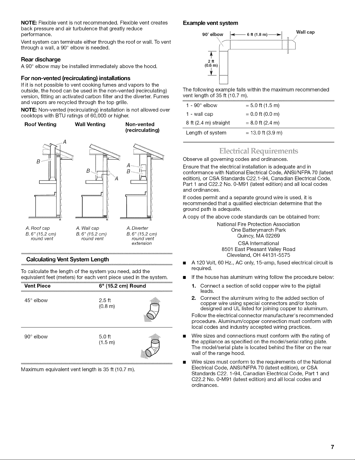
Roof Venting Wall Venting Non-vented
(recirculating)
"A
Bj;
A. Roof cap A. Wall cap A. Diverter
B. 6" (15.2 cm) B. 6" (15.2 cm) B. 6" (15.2 cm)
round vent round vent round vent
Calculating Vent System Length
To calculate the length of the system you need, add the
equivalent feet (meters) for each vent piece used in the system.
Vent Piece 6" (15.2 cm) Round
45° elbow 2.5 ft
extension
(0.8m)
90° elbow 5.0 ft
(1.5m)
Maximum equivalent vent length is 35 ft (10.7 m).
Example vent system
.ooo,bow 8 ......w°,,c°p
The following example falls within the maximum recommended
vent length of 35 ft (10.7 m).
1 - 90 ° elbow = 5.0 ft (1.5 m)
1 - wall cap = 0.0 ft (0.0 m)
8 ft (2.4 m) straight = 8.0 ft (2.4 m)
Length of system = 13.0 ft (3.9 m)
Observe all governing codes and ordinances.
Ensure that the electrical installation is adequate and in
conformance with National Electrical Code, ANSI/NFPA 70 (latest
edition), or CSA Standards C22.1-94, Canadian Electrical Code,
Part 1 and C22.2 No. 0-M91 (latest edition) and all local codes
and ordinances.
If codes permit and a separate ground wire is used, it is
recommended that a qualified electrician determine that the
ground path is adequate.
A copy of the above code standards can be obtained from:
National Fire Protection Association
One Batterymarch Park
Quincy, MA 02269
CSA International
8501 East Pleasant Valley Road
Cleveland, OH 44131-5575
• A 120 Volt, 60 Hz., AC only, 15-amp, fused electrical circuit is
required.
• If the house has aluminum wiring follow the procedure below:
1. Connect a section of solid copper wire to the pigtail
leads.
2. Connect the aluminum wiring to the added section of
copper wire using special connectors and/or tools
designed and UL listed for joining copper to aluminum.
Follow the electrical connector manufacturer's recommended
procedure. Aluminum/copper connection must conform with
local codes and industry accepted wiring practices.
• Wire sizes and connections must conform with the rating of
the appliance as specified on the model/serial rating plate.
The model/serial plate is located behind the filter on the rear
wall of the range hood.
• Wire sizes must conform to the requirements of the National
Electrical Code, ANSI/NFPA 70 (latest edition), or CSA
Standards C22.1-94, Canadian Electrical Code, Part 1 and
C22.2 No. 0-M91 (latest edition) and all local codes and
ordinances.
INSTALLATION INSTRUCTIONS
• It is recommended that the vent system be installed before
hood is installed.
• Before making cutouts, make sure there is proper clearance
within the ceiling or wall for exhaust vent.
• Check your ceiling height and the hood height maximum
before you select your hood.
1. Disconnect power.
2. Determine which venting method to use: roof, wall, or non-
vented.
3. Select a flat surface for assembling the range hood. Place
covering over that surface.
Excessive Weight Hazard
Use two or more people to move and install
range hood.
Failure to do so can result in back or other injury.
4. Using 2 or more people, lift range hood onto covered surface.
Tip the hood on its back and remove filters and set aside. See
"Range Hood Care" section.
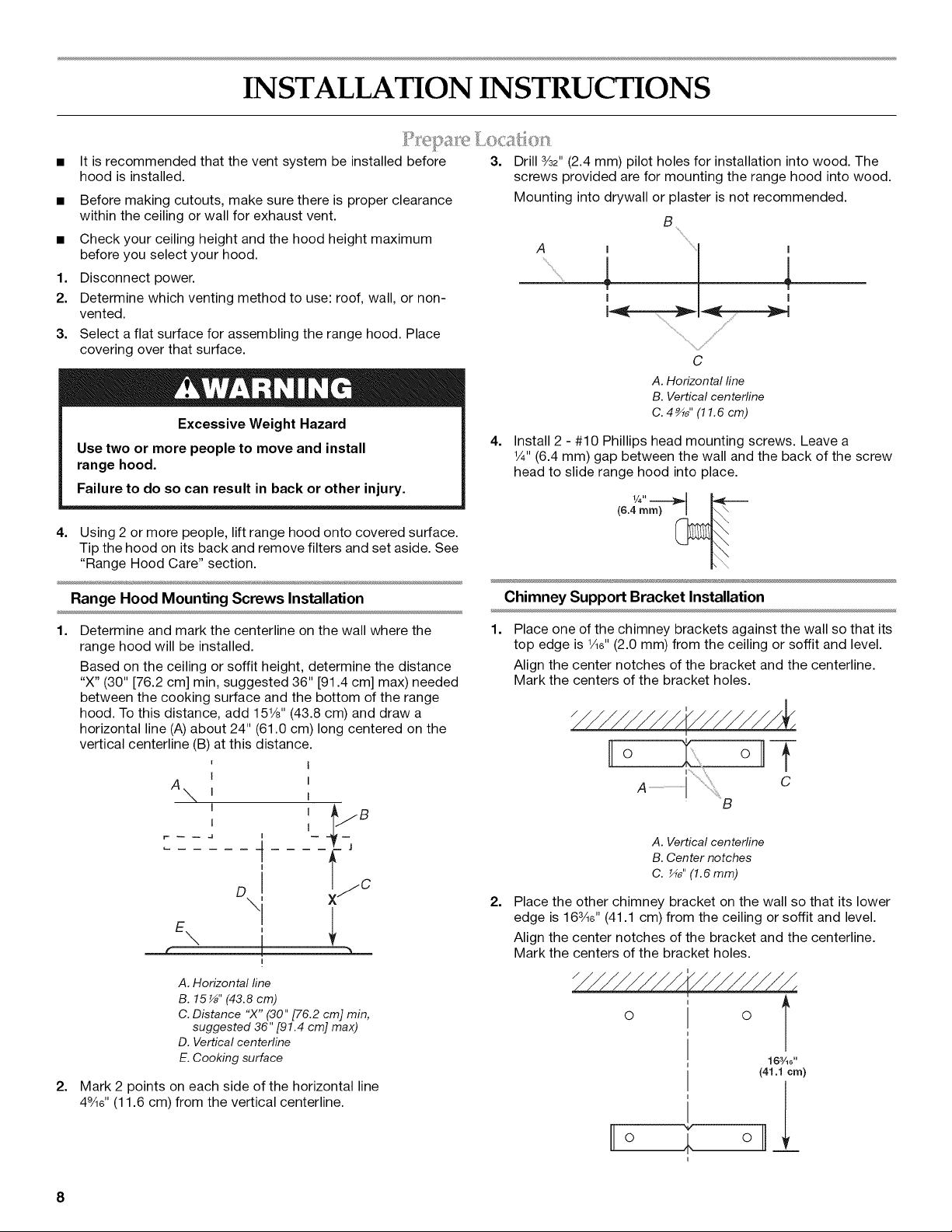
Range Hood Mounting Screws Installation
3.
Drill 3/32"(2.4 mm) pilot holes for installation into wood. The
screws provided are for mounting the range hood into wood.
Mounting into drywall or plaster is not recommended.
B
A
4. Install 2 - #10 Phillips head mounting screws. Leave a
1/4"(6.4 mm) gap between the wall and the back of the screw
head to slide range hood into place.
Chimney Support Bracket Installation
I I
............. /,
C
A. Horizontal fine
B. Vertical centerline
C. 4 _" (11.6 cm)
(6.4 ram) _
1.
Determine and mark the centerline on the wall where the
range hood will be installed.
Based on the ceiling or soffit height, determine the distance
"X" (30" [76.2 cm] min, suggested 36" [91.4 cm] max) needed
between the cooking surface and the bottom of the range
hood. To this distance, add 151/8"(43.8 cm) and draw a
horizontal line (A) about 24" (61.0 cm) long centered on the
vertical centerline (B) at this distance.
I
A
\l
I
1
I
I
I
t
DI c
\
!
I
A. Horizontal fine
B. 15_" (43.8 cm)
C. Distance "X" (30" [76.2 cm] min,
suggested 36" [91.4 cm] max)
D. Vertical centerline
E. Cooking surface
2.
Mark 2 points on each side of the horizontal line
49/16'' (11.6 cm) from the vertical centerline.
1.
Place one of the chimney brackets against the wall so that its
top edge is 1/16"(2.0 mm) from the ceiling or soffit and level.
Align the center notches of the bracket and the centerline.
Mark the centers of the bracket holes.
O
A. Vertical centerline
B. Center notches
C. _" (1.6 mm)
2.
Place the other chimney bracket on the wall so that its lower
edge is 163/16'' (41.1 cm) from the ceiling or soffit and level.
Align the center notches of the bracket and the centerline.
Mark the centers of the bracket holes.
o f
B
°T
16¾0"
(41.1 cm)
V
I O
i
el
8
3. Drill 3/32"(2.4 mm) pilot holes for installation into wood. The
screws provided are for mounting the range hood into wood.
Mounting into drywall or plaster is not recommended.
4. Attach each bracket to the wall with 2 - #10 Phillips head
mounting screws. Tighten screws securely.
Complete Preparation
1.
Determine and make all necessary cuts in the wall for the vent
system. Install the vent system before installing the range
hood. See the "Venting Requirements" section.
2=
Determine the location where the power supply cable will be
run through the wall.
NOTE: For wiring flexibility, the terminal box is external to the
range hood motor. About 24" (61.0 cm) of wire connects the
terminal box to the range hood motor.
Check that the lower chimney cover will hide the selected
location.
3. Drill a 1V4"(3.2 cm) hole at this location.
4. Pull enough power supply cable through the wall to allow for
easy connection to the terminal box.
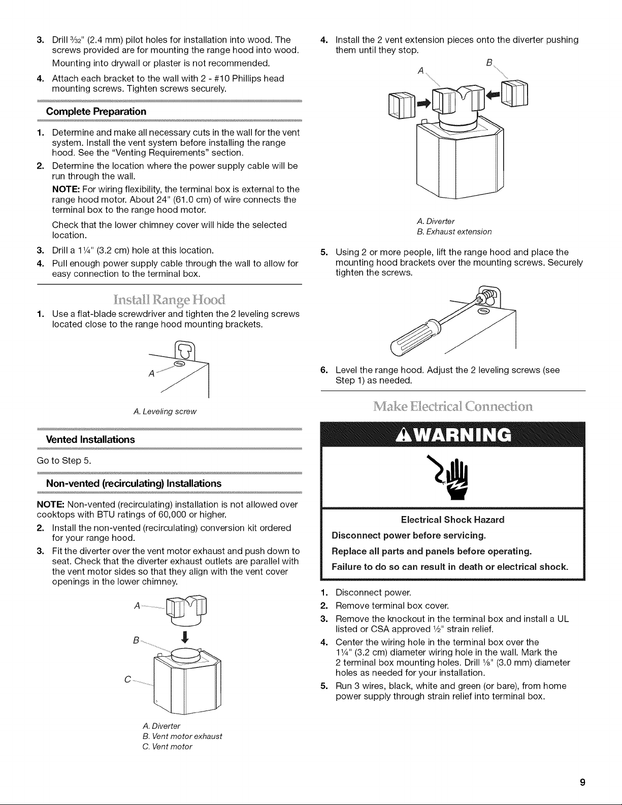
4.
Install the 2 vent extension pieces onto the diverter pushing
them until they stop.
A
A. Diverter
B. Exhaust extension
5.
Using 2 or more people, lift the range hood and place the
mounting hood brackets over the mounting screws. Securely
tighten the screws.
1. Use a flat-blade screwdriver and tighten the 2 leveling screws
_j ....
located close to the range hood mounting brackets.
A.Leveling screw
Vented Installations
Go to Step 5.
Non-vented (recirculating) Installations
NOTE: Non-vented (recirculating) installation is not allowed over
cooktops with BTU ratings of 60,000 or higher.
2. Install the non-vented (recirculating) conversion kit ordered
for your range hood.
3. Fit the diverter over the vent motor exhaust and push down to
seat. Check that the diverter exhaust outlets are parallel with
the vent motor sides so that they align with the vent cover
openings in the lower chimney.
A ..........................................E_
C ................
6. Level the range hood. Adjust the 2 leveling screws (see
Step 1) as needed.
Electrical Shock Hazard
Disconnect power before servicing.
Replace all parts and panels before operating.
Failure to do so can result in death or electrical shock.
1. Disconnect power.
2. Remove terminal box cover.
3. Remove the knockout in the terminal box and install a UL
listed or CSA approved V2"strain relief.
4. Center the wiring hole in the terminal box over the
11¼'' (3.2 cm) diameter wiring hole in the wall. Mark the
2 terminal box mounting holes. Drill V8"(3.0 mm) diameter
holes as needed for your installation.
5. Run 3 wires, black, white and green (or bare), from home
power supply through strain relief into terminal box.
A. Diverter
B. Vent motor exhaust
C. Vent motor
6=
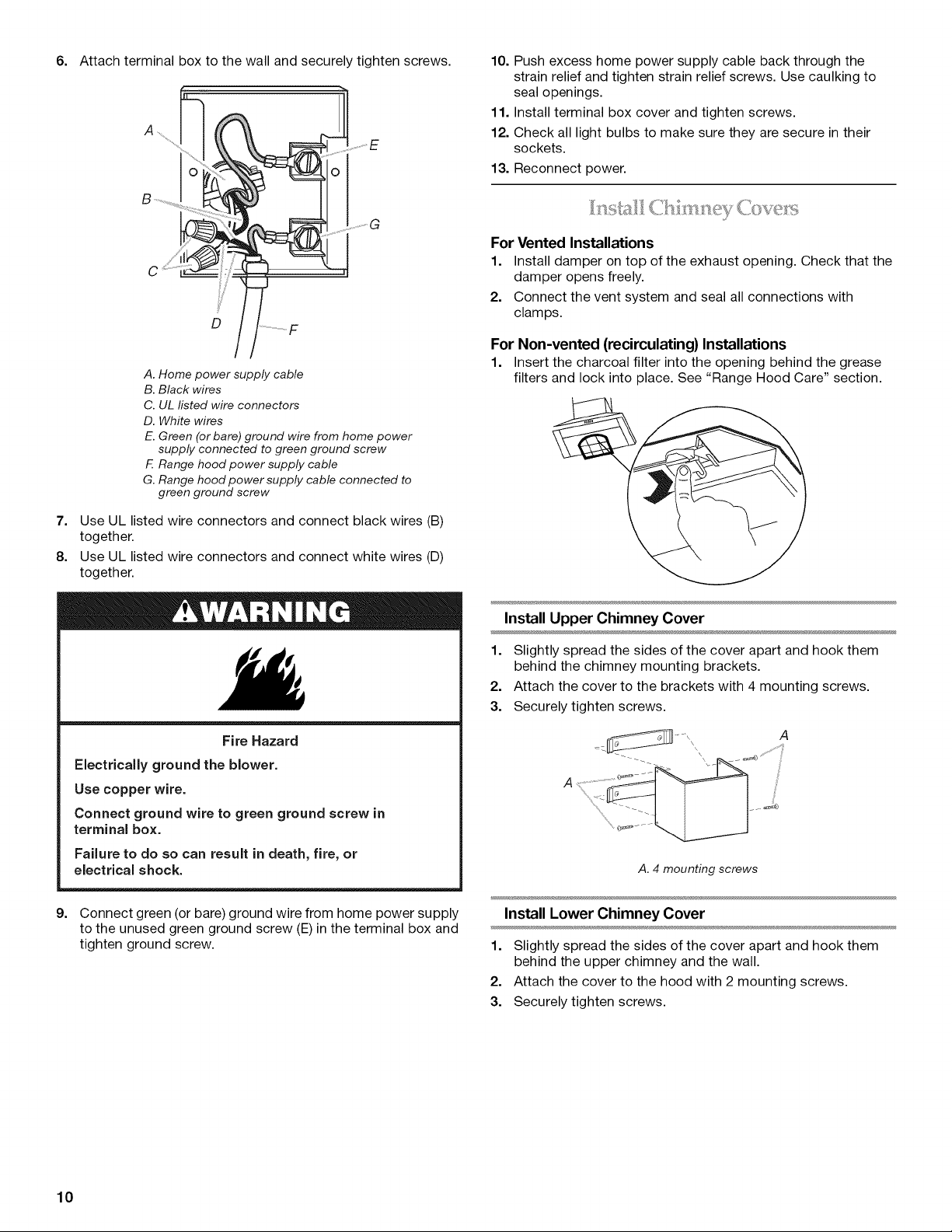
Attach terminal box to the wall and securely tighten screws.
..............E
10. Push excess home power supply cable back through the
strain relief and tighten strain relief screws. Use caulking to
seal openings.
11. Install terminal box cover and tighten screws.
12. Check all light bulbs to make sure they are secure in their
sockets.
13. Reconnect power.
......J G
C
D
A. Home power supply cable
B. Black wires
C. UL listed wire connectors
D. White wires
E. Green (or bare) ground wire from home power
supply connected to green ground screw
F. Range hood power supply cable
G. Range hood power supply cable connected to
green ground screw
7. Use UL listed wire connectors and connect black wires (B)
together.
8. Use UL listed wire connectors and connect white wires (D)
together.
J
For Vented Installations
1. Install damper on top of the exhaust opening. Check that the
damper opens freely.
2. Connect the vent system and seal all connections with
clamps.
For Non-vented (recirculating) Installations
1. Insert the charcoal filter into the opening behind the grease
filters and lock into place. See "Range Hood Care" section.
Install Upper Chimney Cover
1. Slightly spread the sides of the cover apart and hook them
behind the chimney mounting brackets.
2. Attach the cover to the brackets with 4 mounting screws.
3. Securely tighten screws.
Fire Hazard
Electrically ground the blower.
Use copper wire.
Connect ground wire to green ground screw in
terminal box.
Failure to do so can result in death, fire, or
electrical shock.
9. Connect green (or bare) ground wire from home power supply
to the unused green ground screw (E)in the terminal box and
tighten ground screw.
A
A. 4 mounting screws
Install Lower Chimney Cover
1. Slightly spread the sides of the cover apart and hook them
behind the upper chimney and the wall.
2. Attach the cover to the hood with 2 mounting screws.
3. Securely tighten screws.
10
 Loading...