

KitchenAid KWCU360WSS0, KWCU320WSS0 Owner’s Manual
Kitchen_kid ®
30" (76.2 CM), 36" (91.4 CM), 42" (106.7 CM)AND
48" (121.9 CM) COMMERCIAL STYLE
WALL-MOUNT CANOPY RANGE HOOD
For questions about features, operation/performance, parts, accessories or service, call: 1-800-422-1230
In Canada, for assistance, installation and service, call: 1-800-807-6777
or visit our website at www, kitchenaid,com
or visit our website at www, kitchenaid,ca
HO'I'I'E D'EXTRACTION A MONTAGE MURAL
DE STYLE COMMERCIAL DE 30" (76,2 CM),
36" (91,4 CM), 42" (106,7 CM) ET 48" (121,9 CM)
Au Canada, pour assistance, installation ou service composez le 1-800-807-6777
Para obtener acceso al manual de uso y cuidado en espafiol, o para obtener informacion adicional acerca de su producto,
visite: www.kitchenaid.com.
Tenga listo su n0mero de modelo completo. Puede encontrar el n0mero de modelo y de serie dentro de la cavidad superior de la
puerta.
Table of Contents/Table des matieres ............................................................................. 2
ou visitez notre site web & www, kitchenaid,ca
IMPORTANT: READ AND SAVE THESE INSTRUCTIONS.
FOR RESIDENTIAL USE ONLY.
IMPORTANT : LIRE ET CONSERVER CES INSTRUCTIONS.
POUR UTILISATION RI'-=SIDENTIELLE UNIQUEMENT.
W10233972A
TABLEOF CONTENTS
TABLE DES MATIERES
RANGE HOOD SAFETY ................................................................. 3
INSTALLATION REQUIREMENTS ................................................ 4
Tools and Parts ............................................................................ 4
Location Requirements ................................................................ 5
Venting Requirements .................................................................. 6
Electrical Requirements ............................................................... 7
INSTALLATION INSTRUCTIONS .................................................. 8
Prepare Location .......................................................................... 8
Change Hood to Optional Rear Exhaust ..................................... 8
Install Range Hood ..................................................................... 10
Make Electrical Connection ....................................................... 10
Install Grease Filters ................................................................... 11
Check Operation ........................................................................ 11
RANGE HOOD USE ...................................................................... 11
Range Hood Controls ................................................................ 11
RANGE HOOD CARE ................................................................... 12
Range Hood Lamps ................................................................... 12
Cleaning ...................................................................................... 12
WIRING DIAGRAM ....................................................................... 13
ASSISTANCE OR SERVICE ......................................................... 14
Accessories ................................................................................ 14
WAR RANTY ............................................................................... 15
SI_CURITI_ DE LA HOTTE DE CUlSINIF:RE ............................... 16
EXIGENCES D'INSTALLATION ................................................... 18
Outillage et pieces ...................................................................... 18
Exigences d'emplacement ......................................................... 18
Exigences concernant I'evacuation ........................................... 19
Specifications electriques .......................................................... 20
INSTRUCTIONS D'INSTALLATION ............................................. 21
Preparation de I'emplacement ................................................... 21
Modification de la hotte pour evacuation par
I'arriere facultative ...................................................................... 21
Installation de la hotte ................................................................ 23
Raccordement electrique ........................................................... 23
Installation des filtres a graisse .................................................. 24
Contr61e du fonctionnement ...................................................... 24
UTILISATION DE LA Ho'n'E ....................................................... 24
Commandes de la hotte de cuisiniere ....................................... 24
ENTRETIEN DE LA HOTTE DE CUlSINIF:RE ............................. 25
Lampes de la hotte de cuisiniere ............................................... 25
Nettoyage ................................................................................... 25
SCHI_MA DE C.&,BLAGE............................................................... 26
ASSISTANCE OU SERVICE ......................................................... 27
Accessoires ................................................................................ 27
GARANTIE ..................................................................................... 28
2
RANGE HOOD SAFETY
Your safety and the safety of others are very important.
We have provided many important safety messages in this manual and on your appliance. Always read and obey all safety
messages.
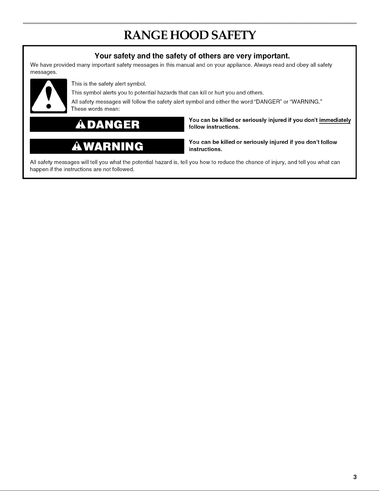
This is the safety alert symbol.
This symbol alerts you to potential hazards that can kill or hurt you and others.
All safety messages will follow the safety alert symbol and either the word "DANGER" or "WARNING."
These words mean:
You can be killed or seriously injured if you don't immediately
follow instructions.
You can be killed or seriously injured if you don't follow
instructions.
All safety messages will tell you what the potential hazard is, tell you how to reduce the chance of injury, and tell you what can
happen if the instructions are not followed.
iMPORTANT SAFETY iNSTRUCTiONS
WARNING: TO REDUCE THE RISK OF FIRE, ELECTRIC
SHOCK, OR INJURY TO PERSONS, OBSERVE THE
FOLLOWING:
• Use this unit only in the manner intended by the
manufacturer. If you have questions, contact the
manufacturer.
• Before servicing or cleaning the unit, switch power off at
service panel and lock the service disconnecting means to
prevent power from being switched on accidentally. When
the service disconnecting means cannot be locked,
securely fasten a prominent warning device, such as a tag,
to the service panel.
• Installation work and electrical wiring must be done by
qualified person(s) in accordance with all applicable codes
and standards, including fire-rated construction.
• Sufficient air is needed for proper combustion and
exhausting of gases through the flue (chimney) of fuel
burning equipment to prevent backdrafting. Follow the
heating equipment manufacturer's guideline and safety
standards such as those published by the National Fire
Protection Association (NFPA), the American Society for
Heating, Refrigeration and Air Conditioning Engineers
(ASHRAE), and the local code authorities.
• When cutting or drilling into wall or ceiling; do not damage
electrical wiring and other utilities.
• Ducted fans must always be vented outdoors.
CAUTION: For general ventilating use only. Do not use
to exhaust hazardous or explosive materials and vapors.
CAUTION: To reduce risk of fire and to properly exhaust
air, be sure to duct air outside - do not vent exhaust air into
spaces within walls or ceilings, attics or into crawl spaces,
or garages.
WARNING: TO REDUCE THE RISK OF FIRE, USE ONLY
METAL DUCTWORK.
WARNING: TO REDUCE THE RISK OF A RANGE TOP
GREASE FIRE:
[] Never leave surface units unattended at high settings.
Boilovers cause smoking and greasy spillovers that may
ignite. Heat oils slowly on low or medium settings.
[] Always turn hood ON when cooking at high heat or when
flambeing food (i.e. Crepes Suzette, Cherries Jubilee,
Peppercorn Beef Flamb6).
[] Clean ventilating fans frequently. Grease should not be
allowed to accumulate on fan or filter.
[] Use proper pan size. Always use cookware appropriate for
the size of the surface element.
WARNING: TO REDUCE THE RISK OF INJURY TO
PERSONS IN THE EVENT OF A RANGE TOP GREASE
FIRE, OBSERVE THE FOLLOWING: a
[] SMOTHER FLAMES with a close fitting lid, cookie sheet, or
metal tray, then turn off the burner. BE CAREFUL TO
PREVENT BURNS. If the flames do not go out
immediately, EVACUATE AND CALL THE FIRE
DEPARTMENT.
[] NEVER PICK UP A FLAMING PAN -you may be burned.
[] DO NOT USE WATER, including wet dishcloths or towels -
a violent steam explosion will result.
[] Use an extinguisher ONLY if:
- You know you have a class ABC extinguisher, and you
already know how to operate it.
- The fire is small and contained in the area where it
started.
- The fire department is being called.
- You can fight the fire with your back to an exit.
aBased on "Kitchen Fire Safety Tips" published by NFPA.
[] WARNING: To reduce the risk of fire or electrical shock,
do not use this fan with any solid-state speed control
device.
SAVE THESE iNSTRUCTiONS
INSTALLATION REQUIREMENTS
Gather the required tools and parts before starting installation.
Read and follow the instructions provided with any tools listed
here.
Tools needed
• Level
• Drill
• 1W' (3 cm) drill bit
• 1/8"(3 mm) drill bit if installing into wood and a 5/_e"(8 mm) drill
bit if installing optional backsplash kit.
• Pencil
• Wire stripper or utility knife
• Tape measure or ruler
• Pliers
• Caulking gun and weatherproof caulking compound
• Vent clamps
• Jigsaw or keyhole saw
• Flat-blade screwdriver
• Metal snips
• Phillips screwdriver
• Scissors
Parts needed
• Home power supply cable
• 1 - 1/2"(12.7 mm) UL listed or CSA approved strain relief
• 2 UL listed wire connectors
• 1 wall or roof cap
• Metal vent system
Parts supplied
Remove parts from packages. Check that all parts are included.
• 2 metal grease filters for 30" (76.2 cm) models
3 metal grease filters for 36" (91.4 cm) models
3 metal grease filters for 42" (106.7 cm) models
4 metal grease filters for 48" (121.9 cm) models
• 2 mounting brackets with adjustment screws installed
• 2 mounting bracket screws
• 4 washer head Phillips mounting screws
• Damper
• 2 dampers for 48" (121.9 cm) model.
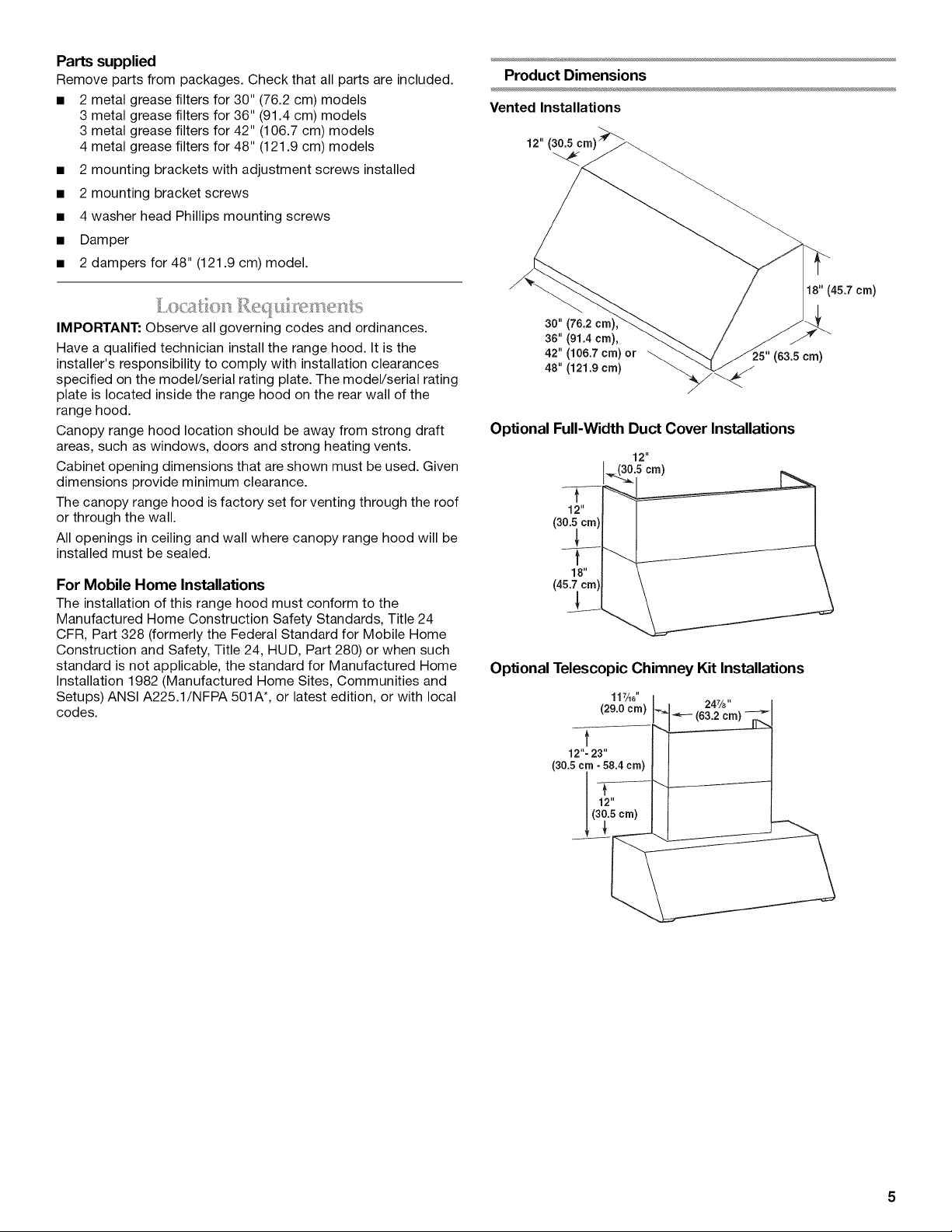
Product Dimensions
Vented Installations
18" (45.7 cm)
IMPORTANT: Observe all governing codes and ordinances.
Have a qualified technician install the range hood. It is the
installer's responsibility to comply with installation clearances
specified on the model/serial rating plate. The model/serial rating
plate is located inside the range hood on the rear wall of the
range hood.
Canopy range hood location should be away from strong draft
areas, such as windows, doors and strong heating vents.
Cabinet opening dimensions that are shown must be used. Given
dimensions provide minimum clearance.
The canopy range hood is factory set for venting through the roof
or through the wall.
All openings in ceiling and wall where canopy range hood will be
installed must be sealed.
For Mobile Home Installations
The installation of this range hood must conform to the
Manufactured Home Construction Safety Standards, Title 24
CFR, Part 328 (formerly the Federal Standard for Mobile Home
Construction and Safety, Title 24, HUD, Part 280) or when such
standard is not applicable, the standard for Manufactured Home
Installation 1982 (Manufactured Home Sites, Communities and
Setups) ANSI A225.1/NFPA 501A*, or latest edition, or with local
codes.
30" (76.2
36" (91.4 cm),
42" (106.7 crn) or
48" (121.9 cm)
(63.5 cm)
Optional Full-Width Duct Cover Installations
12"
._(30.5crn)
t
12"
J
18"
Optional Telescopic Chimney Kit Installations
117A_" 24z/8.
(29.o (63.2cm>
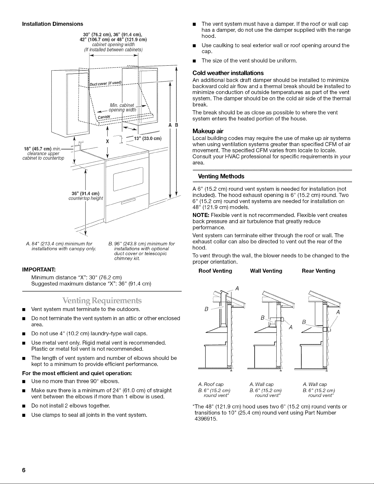
Installation Dimensions
18"(45.7crn)
clearanceupper
cabinettocountertop
30"(76.2cm),36" (91.4crn),
42" (106.7cm)or 48"(121.9crn)
cabinetopeningwidth
(Ifinstalledbetweencabinets
The vent system must have a damper. If the roof or wall cap
has a damper, do not use the damper supplied with the range
hood.
• Use caulking to seal exterior wall or roof opening around the
cap.
• The size of the vent should be uniform.
Cold weather installations
An additional back draft damper should be installed to minimize
backward cold air flow and athermal break should be installed to
minimize conduction of outside temperatures as part of the vent
system. The damper should be on the cold air side of the thermal
break.
The break should be as close as possible to where the vent
system enters the heated portion of the house.
Makeup air
Local building codes may require the use of make up air systems
when using ventilation systems greater than specified CFM of air
movement. The specified CFM varies from locale to locale.
Consult your HVAC professional for specific requirements in your
area.
Venting Methods
3s"(91.4cm)
countertopheight
A. 84" (213.4 cm) minimum for
installations with canopy only.
IMPORTANT:
Minimum distance "X": 30" (76.2 cm)
Suggested maximum distance "X": 36" (91.4 cm)
Vent system must terminate to the outdoors.
Do not terminate the vent system in an attic or other enclosed
area.
• Do not use 4" (10.2 cm) laundry-type wall caps.
• Use metal vent only. Rigid metal vent is recommended.
Plastic or metal foil vent is not recommended.
• The length of vent system and number of elbows should be
kept to a minimum to provide efficient performance.
For the most efficient and quiet operation:
• Use no more than three 90° elbows.
• Make sure there is a minimum of 24" (61.0 cm) of straight
vent between the elbows if more than 1 elbow is used.
• Do not install 2 elbows together.
• Use clamps to seal all joints in the vent system.
B. 96" (243.8 cm) minimum for
installations with optional
duct cover or telescopic
chimney kit.
A 6" (15.2 cm) round vent system is needed for installation (not
L
J
included). The hood exhaust opening is 6" (15.2 cm) round. Two
6" (15.2 cm) round vent systems are needed for installation on
48" (121.9 cm) models.
NOTE: Flexible vent is not recommended. Flexible vent creates
back pressure and air turbulence that greatly reduce
performance.
Vent system can terminate either through the roof or wall. The
exhaust collar can also be directed to vent out the rear of the
hood.
To vent through the wall, the blower needs to be changed to the
proper orientation.
Roof Venting Wall Venting Rear Venting
A
A
//'
A. Roof cap A. Waft cap A. Waft cap
B. 6" (15.2 cm) B. 6" (15.2 cm) B. 6" (15.2 cm)
round vent* round vent* round vent*
*The 48" (121.9 cm) hood uses two 6" (15.2 cm) round vents or
transitions to 10" (25.4 cm) round vent using Part Number
4396915.
6
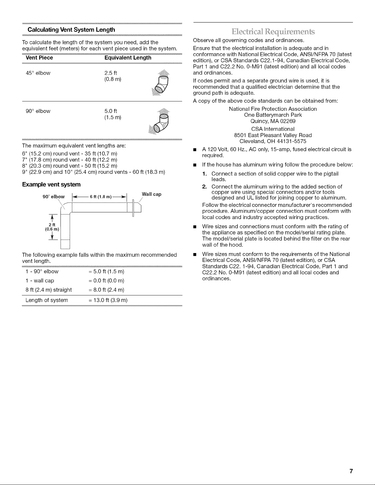
Calculating Vent System Length
To calculate the length of the system you need, add the
equivalent feet (meters) for each vent piece used in the system.
Vent Piece Equivalent Length
45° elbow 2.5 ft
(0.8 m)
90° elbow 5.0 ft
(1.5 m)
The maximum equivalent vent lengths are:
6" (15.2 cm) round vent - 35 ft (10.7 m)
7" (17.8 cm) round vent - 40 ft (12.2 m)
8" (20.3 cm) round vent - 50 ft (15.2 m)
9" (22.9 cm) and 10" (25.4 cm) round vents - 60 ft (18.3 m)
Example vent system
90° elbow I-_ 6. (1.6m)-_l Wall cap
(0.6rn)
2.
!_
/ I
Thefollowing example falls within the maximum recommended
vent length.
1 - 90° elbow = 5.0 ft (1.5 m)
1 - wall cap = 0.0 ft (0.0 m)
8 ft (2.4 m) straight = 8.0 ft (2.4 m)
Length of system = 13.0 ft (3.9 m)
Observe all governing codes and ordinances.
Ensure that the electrical installation is adequate and in
conformance with National Electrical Code, ANSl/NFPA 70 (latest
edition), or CSA Standards C22.1-94, Canadian Electrical Code,
Part 1 and C22.2 No. 0-M91 (latest edition) and all local codes
and ordinances.
If codes permit and a separate ground wire is used, it is
recommended that a qualified electrician determine that the
ground path is adequate.
A copy of the above code standards can be obtained from:
National Fire Protection Association
One Batterymarch Park
Quincy, MA 02269
CSA International
8501 East Pleasant Valley Road
Cleveland, OH 44131-5575
• A 120 Volt, 60 Hz., AC only, 15-amp, fused electrical circuit is
required.
• If the house has aluminum wiring follow the procedure below:
1. Connect a section of solid copper wire to the pigtail
leads.
2. Connect the aluminum wiring to the added section of
copper wire using special connectors and/or tools
designed and UL listed for joining copper to aluminum.
Follow the electrical connector manufacturer's recommended
procedure. Aluminum/copper connection must conform with
local codes and industry accepted wiring practices.
• Wire sizes and connections must conform with the rating of
the appliance as specified on the model/serial rating plate.
The model/serial plate is located behind the filter on the rear
wall of the hood.
Wire sizes must conform to the requirements of the National
Electrical Code, ANSl/NFPA 70 (latest edition), or CSA
Standards C22.1-94, Canadian Electrical Code, Part 1 and
C22.2 No. 0-M91 (latest edition) and all local codes and
ordinances.
INSTALLATION INSTRUCTIONS
• It is recommended that the vent system be installed before
hood is installed.
• Before making cutouts, make sure there is proper clearance
within the ceiling or wall for exhaust vent.
• Check that all installation parts have been removed from the
shipping carton.
1. Disconnect power.
2. Determine which venting method to use: roof, wall or rear
exhaust.
3. Select a flat surface for assembling the range hood. Place
covering over that surface.
Excessive Weight Hazard
Use two or more people to move and install
range hood.
Failure to do so can result in back or other injury.
4. Using 2 or more people, lift rangehood onto covered surface.
Optional Backsplash Installation
The following instructions are for the backsplash without shelves.
Ifyou are installing the Optional Backsplash with Shelves for Heat
Lamps, follow the instructions included with that product.
The hardware package supplied with the kit includes 4 plastic
wall anchors and mounting screws.
NOTE: The minimum height of the hood above the cooktop is
30" (76.2 cm). The backsplash can be extended from 1923/32''
(50.1 cm) to 39" (99.1 cm). As the 30" (76.2 cm) installation
height increases, the hood's capture area decreases.
• Determine height of the hood.
• For ease of installation, use 2 or more people to position the
backsplash on the wall so that the top of the backsplash is at
the height of the bottom edge of the hood. Mark the location
of the four corner holes. It is recommended that the
backsplash be attached to the wall at all four corners.
However, the lower flange can be secured between the wall
and backspash, countertop or cabinet base without using the
bottom corner screws.
• Drill 5A6"(8 mm) holes.
• Push plastic wall anchors all the way into the holes.
• Position the holes in the backsplash over the wall anchors
and attach using the screws supplied.
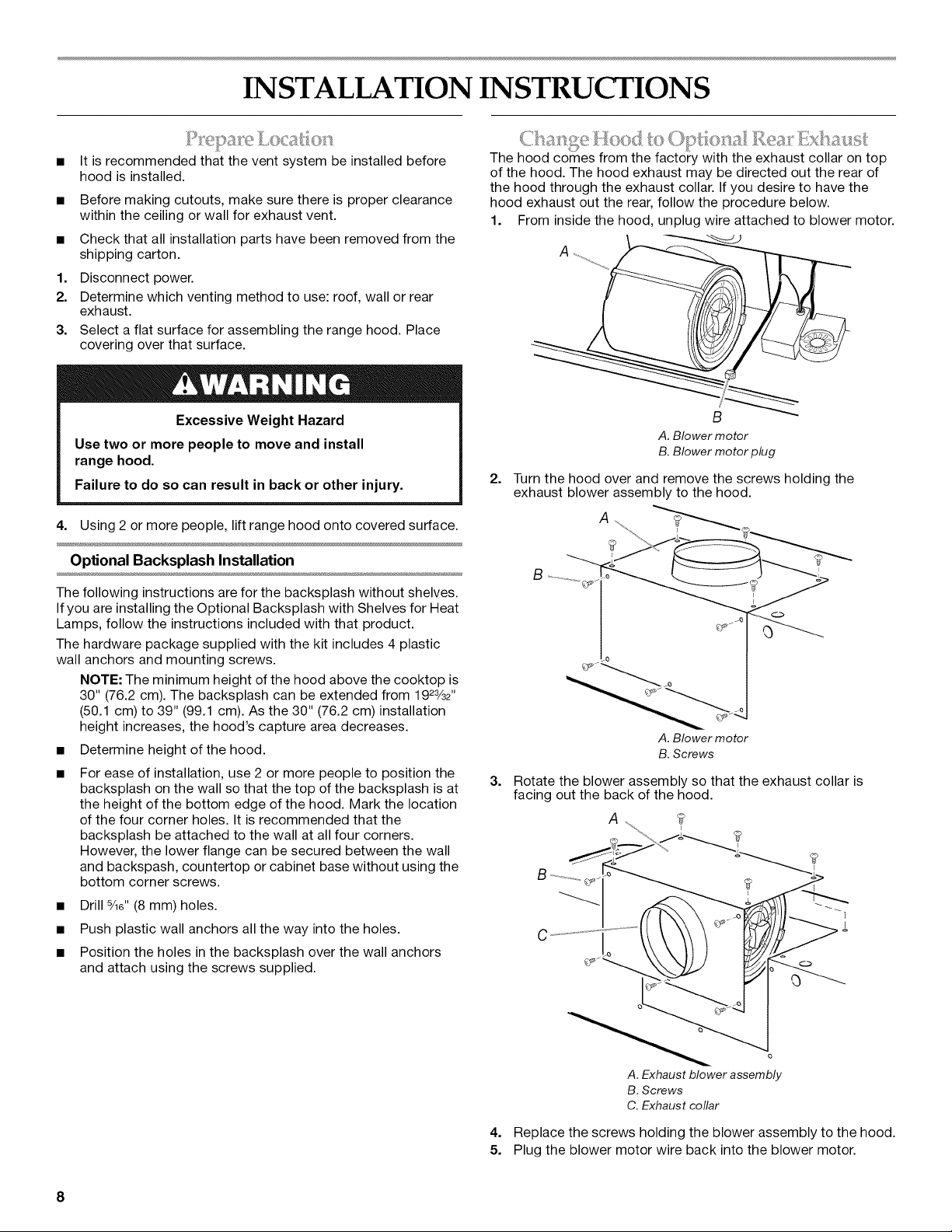
The hood comes from the factory with the exhaust collar on top
of the hood. The hood exhaust may be directed out the rear of
the hood through the exhaust collar. If you desire to have the
hood exhaust out the rear, follow the procedure below.
1. From inside the hood, unplug wire attached to blower motor.
A
B
A.Blower motor
B.Blower motor plug
2. Turn the hood over and remove the screws holding the
exhaust blower assembly to the hood.
A
?
A. Blower motor
B.Screws
3. Rotate the blower assembly so that the exhaust collar is
facing out the back of the hood.
A
A.Exhaust blower assembly
B.Screws
C.Exhaust collar
4. Replace the screws holding the blower assembly to the hood.
5. Plug the blower motor wire back into the blower motor.
8
Range Hood Mounting Screws Installation
• The hood attaches to the wall with two mounting brackets
with adjustment screws and four mounting screws.
1. Determine and mark the centerline on the wall where the
canopy range hood will be installed.
2. Select a mounting height between a minimum of 30" (76.2 cm)
and a suggested maximum of 36" (91.4 cm), above the
cooking surface and the bottom of the range hood. To this
distance, add 16" (40.6 cm) and mark a horizontal line.
3. Mark 2 points on each side of the horizontal line the distance
shown in "A" below (based on the size of your range hood).
D
B C
A. Distance from center of mounting
bracket to centerline.
30" (76.2 cm) hood:
13_" (34.0 cm)
36" (91.4 cm) hood:
16_" (41.6 cm)
42" (106. 7 cm) hood:
19 _" (49.4 cm)
48" (121.9 cm) hood:
22_" (56.8 cm)
4,
Adjust the two adjusting screws on the mounting brackets to
B. Mounting screws (4)
C. Mounting brackets and
adjustment screws
D. Bottom of hood
the lowest point and attach to the wall with the screws
provided. The screws provided for mounting this hood must
be fastened into solid wood. Do not fasten into sheet rock
only.
Optional Duct Cover Installation
1. Attach the full-width duct cover to the top of the range hood
with the screws provided. The duct cover must be attached
to the top of the range hood before mounting the range hood
to the wall. For information on ordering the optional duct
cover, see "Accessories" section.
2, Install each bracket on the wall as shown. Make sure the
screws and brackets are securely fastened to the wall.
IMPORTANT: Install only the brackets. Do not install the
hood.
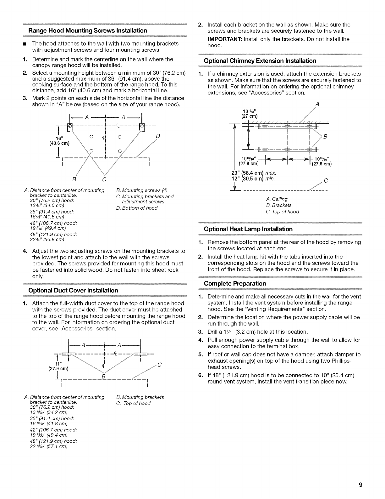
Optional Chimney Extension Installation
1. If a chimney extension is used, attach the extension brackets
as shown. Make sure that the screws are securely fastened to
the wall. For information on ordering the optional chimney
extensions, see "Accessories" section.
A
10%" ,//
(27 cm) //
/ _ / / / A / / / / / / / / J'/// / / / /
_ _ __ _ _ "_
i i i/
1ow,o"__ 10,5/,o"
(27.8cm) (27.8cm)
23" (58.4 crn) max.
12" (30.5 cm) min.
k ///C
A. Ceiling
B. Brackets
C. Top of hood
Optional Heat Lamp Installation
1. Remove the bottom panel at the rear of the hood by removing
the screws located at each end.
2. Install the heat lamp kit with the tabs inserted into the
corresponding slots on the hood and the screws toward the
front of the hood. Replace the screws to secure it in place.
Complete Preparation
1. Determine and make all necessary cuts in the wall for the vent
system. Install the vent system before installing the range
hood. See the "Venting Requirements" section.
2. Determine the location where the power supply cable will be
run through the wall.
3. Drill a 1V4"(3.2 cm) hole at this location.
4. Pull enough power supply cable through the wall to allow for
easy connection to the terminal box.
5. If roof or wall cap does not have a damper, attach damper to
exhaust opening(s) on top of the hood using two Phillips-
head screws.
6. If 48" (121.9 cm) hood is to be connected to 10" (25.4 cm)
round vent system, install the vent transition piece now.
A. Distance from center of mounting
bracket to centerline.
30" (76.2 cm) hood:
13 r_2" (34.2 cm)
36" (91.4 cm) hood:
16 r_2" (41.8 cm)
42" (106. 7 cm) hood:
191_2" (49.4 cm)
48" (121.9 cm) hood:
22 r_2" (57.1 cm)
B. Mounting brackets
C. Top of hood
 Loading...