

KitchenAid KWCU265HBT1, KWCU265HWH1, KWCU265HSS1, KWCU205HWH1, KWCU205HSS1 Owner’s Manual
...
iMPORTANT:
Read and save
these instructions.
iMPORTANT:
installer: Leave Installation instructionswith
the homeowner.
Homeowner: Keep Installation Instructions for
future reference.
Save Installation Instructions for local electrical
inspector'suse.
4329224/9763386
Quick Reference
Table of Contents:
Pages
[] Before you start
[] Product dimensions
[] Cabinet dimensions
[] Venting requirements
[] Electrical requirements
[_- [] Installation steps
[] Use and Care Information
[] Wiring diagram
[] Accessories
[] Warranty
[]- [] Requesting Assistance or
Service
Your safety and the safety of
others is very important.
We haveprovided many important
safety messagesin this manual and
on your appliance. Always readand
obey all safety messages.
This is the safety alertsymbol.
This symbol alerts you to
potential hazardsthat can kill
or hurt you and others. All safety
messageswill follow the safety alert
symbol and either the word "DANGER"
or "WARNING". Thesewords mean:
Youcanbe killed or seriouslyinjured
if you don'tfollow instructions.
All safety messageswiil tell you what
the potential hazard is, tell you how to
reducethe chance of injury, and tell
you what can happenif the
instructions are not followed.
WARNING -- TO REDUCE THE
RISK OF FIRE, ELECTRIC SHOCK,
OR INJURYTO PERSONS,
OBSERVE THE FOLLOWING:
Installation work and electrical
wiring must be done by qualified
person(s) in accordance with all
applicable Codes and Standards,
including Fire Rated
Construction. The combustion
airflow needed for safe
operation of fuel-burning
equipment may be affected by
this unit's operation. Follow the
heating equipment
manufacturer's guideline and
safety standards such as those
published by the National Fire
Protection Association (NFPA),
and the American Society of
Heating, Refrigeration and Air
Conditioning Engineers
(ASHRAE), and the local code
authorities.
When cutting or drilling into wall
or ceiling, do not damage
electrical wiring and other
hidden utilities.
Ducted fans must always be
vented to the outdoors.
WARNING --To reduce the risk
of fire, use only metal ductwork.
This unit must be grounded.
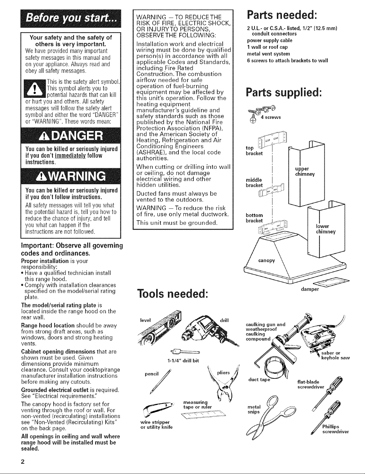
Partsneeded:
2 U.L.- or C.S.A.- listed, 1/2" (12.5 mm}
conduit connectors
power supply cable
1wall or roof cap
metal vent system
6 screws to attach brackets to wall
Parts supplied:
top
bracket
upper
chimney
middle
bracket
__L
bottom
bracket
important: Observe all governing
codes and ordinances.
Proper installation is your
responsibility:
• Have a qualified technician install
this range hood.
• Comply with installation clearances
specified on the model/serial rating
plate.
The model/serial rating plate is
located inside the range hood on the
rear wall.
Range hood location should be away
from strong draft areas, such as
windows, doors and strong heating
vents.
Cabinet opening dimensions that are
shown must be used. Given
dimensions provide minimum
clearance. Consult your cooktop/range
manufacturer installation instructions
before making any cutouts.
Grounded electrical outlet is required.
See "Electrical requirements."
The canopy hood is factory set for
venting through the roof or wall. For
non-vented (recirculating)installations
see "Non-Vented (Recirculating) Kits"
on the back page.
All openings in ceiling and wall where
range hood will be installed must be
sealed.
Tools needed:
level drill
1-1/4" drill bit
measuring
tape or ruler
wire stripper
or utility knife
damper
caulking gun and
weatherproof
caulking
compound
saber or
keyhole saw
duct talc
screwdriver
screwdriver
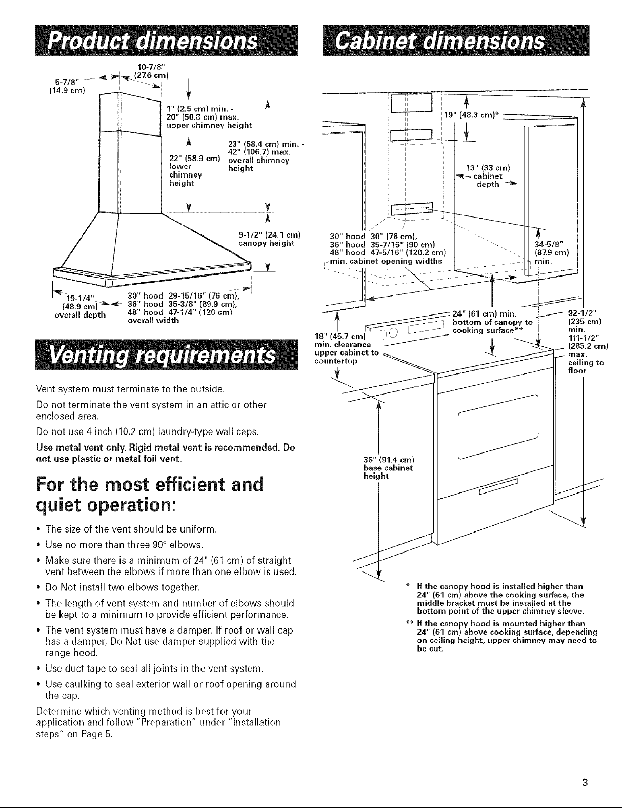
5-7/8......
(14.9cm)
10-7/8"
1" 12.5 cm) min. -
20" (50.8 cm) max.
upper chimney height
23" (58.4 cm) rain.
22" (58.9 cm) overaff chimney
lower height
chimney
height
30" hood 29-15/16" (76 cm),
overall depth 48" hood 47-1/4" (120 cm)
i 36" hood 35-3/8" (89.9 cm),
overall width
42" (106.7) max,
i
Vent system must terminate to the outside.
Do not terminate the vent system in an attic or other
enclosed area.
Do not use 4 inch (10.2 cm) laundry-type wall caps.
Use metal vent only. Rigid metal vent is recommended. Do
not use plastic or metal foil vent.
For the most efficient and
i '
;_ _ b I ......
30" hood 30" (76 era), -_
38" hood 35-7/16" (go cm) _ 34-5/8"
48" hood 47-5/16" (120.2 cm) "'- (87.9 cm)
_min. cabinet opening widths ..... / rain.
i _ 24" (61 cm) rain. / 92-1/2"
T ___ 7 bottom of canopy to (235 cm)
. ;...... cookingsurface-- rain
18" t45.7 cml ;_ / i _ 111-1/2"
rain. clearance _ _€ (283.2 cm)
upper caomet to _L max.
countertop
36" (91.4 cm)
base cabinet
height
lg" (48.3 cm)*
13" (33 cm)
cabinet
depth
ceiling to
floor
quiet operation:
• The size of the vent should be uniform.
• Use no more than three 90° elbows.
• Make sure there is a minimum of 24" (61 cm) of straight
vent between the elbows if more than one elbow is used.
• Do Not install two elbows together.
• The length of vent system and number of elbows should
be kept to a minimum to provide efficient performance.
• The vent system must have a damper. If roof or wall cap
has a damper, Do Not use damper supplied with the
range hood.
• Use duct tape to seal all joints in the vent system.
• Use caulking to seal exterior wall or roof opening around
the cap.
Determine which venting method is best for your
application and follow "Preparation" under "Installation
steps" on Page 5.
* If the canopy hood is installed higher than
24" (81 cm) above the cooking surface, the
middle bracket must be installed at the
bottom point of the upper chimney sleeve,
** If the canopy hood is mounted higher than
24" (61 cm) above cooking surface, depending
on ceiling height, upper chimney may need to
be cut.
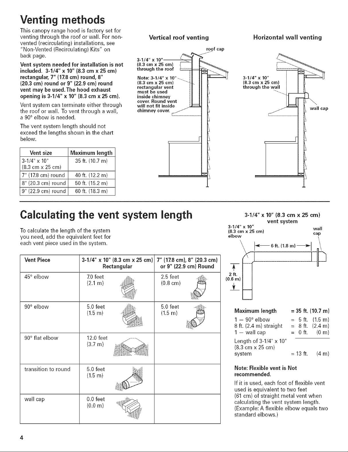
Venting methods
This canopy range hood isfactory set for
venting through the roof or wall. For non-
vented (recirculating)installations, see
"Non-Vented (Recirculating) Kits" on
back page.
Vent system needed for installation is not
included. 3-1/4" x 10" (8.3cmx 25 cm)
rectangular, 7" (17.8cm) round, 8"
(20.3 cm) round or 9" (22.9 cm) round
vent may be used.The hood exhaust
opening is 3-1/4" x 10" (8.3 cmx 25 cm).
Vent system can terminate either through
the roof or wall. Tovent through a wall,
a 90° elbow is needed.
The vent system length should not
exceed the lengths shown in the chart
below,
Vent size Maximum length
3-1/4" x 10" 35 ft. (10.7m)
(8.3 cmx 25 cm)
7"(17.8cm) round 40 ft. (12.2 m)
8" (20.3 cm) round 50ft. (15.2 m)
9" (22.9 cm) round 60ft. (18.3 m)
Vertical roof venting
roof cap
3-1/4" x 10" _'_
(8.3cmx 25 cm) / ] L TM
through the roof _ _:_..'_
i
Horizontal wall venting
3-1/4-" x 10" F I
Calculating the vent system length
To calculate the length of the system
you need, add the equivalent feet for
each vent piece used in the system,
Vent Piece
45° elbow
90° elbow
90° flat elbow
transition to round
wall cap
3-1/4" x 10" (8.3 cm x 25 cm}
Rectangular
7.0feet
(2.1 m)
5.0 feet
(1.5 m)
12.0 feet
(3.7 m)
5.0 feet
(1.5 m)
0.0 feet
(0.0 m)
7" (17.8cm), 8" (20.3cm}
or 9" (22.9 cm} Round
2.5feet
(0.8cm)
5.0feet
(1.5m)
3-1/4" x 10" (8.3 cmx 25 cm)
vent system
3-1/4" x 10" wail
(8,3 cm x 25 crn)
elbow cap
Maximum length = 35 ft. (10.7m)
1-90 ° elbow = 5ft. (1.5m)
8 ft. (2.4 m) straight = 8 ft. (2.4 m)
1 -wallcap = Oft. (Ore)
Length of 3-1/4" x 10"
(8.3 cmx 25 cm)
system = 13 ft. (4 m)
Note: Flexible vent is Not
recommended.
If it is used, each foot of flexible vent
used is equivalent to two feet
(61 cm) of straight metal vent when
calculating the vent system length,
(Example: A flexible elbow equals two
standard elbows,)
 Loading...