

KitchenAid KVWB606HBS0, KVWB600HBS0 Owner’s Manual
30” (76.2 CM) AND 36” (91.4 CM)
WALL-MOUNT CANOPY RANGE HOOD
Installation Instructions and Use and Care Guide
For questions about features, operation/performance, parts, accessories or service, call: 1-800-422-1230
or visit our website at www.kitchenaid.com
In Canada, for assistance, installation and service, call: 1-800-807-6777
or visit our website at www.kitchenaid.ca
HOTTE D’EXTRACTION À MONTAGE MURAL
DE 30" (76,2 CM) ET 36" (91,4 CM)
Instructions d’installation et Guide d’utilisation et d’entretien
Au Canada, pour assistance, installation ou service, composez le 1-800-807-6777
ou visitez notre site web à www.kitchenaid.ca
IMPORTANT: READ AND SAVE THESE INSTRUCTIONS. FOR RESIDENTIAL USE ONLY.
IMPORTANT : LIRE ET CONSERVER CES INSTRUCTIONS. POUR UTILISATION RÉSIDENTIELLE UNIQUEMENT.
LIB0143609/W11230974B

TABLE OF CONTENTS
RANGE HOOD SAFETY .................................................................3
INSTALLATION REQUIREMENTS .................................................5
Tools and Parts ............................................................................. 5
Location Requirements ................................................................5
Venting Requirements ..................................................................6
Electrical Requirements ...............................................................7
INSTALLATION INSTRUCTIONS ...................................................8
Prepare Location ..........................................................................8
Install Range Hood .......................................................................9
Connect Vent System ..................................................................9
Make Electrical Connection .......................................................10
Install Vent Covers ......................................................................11
Complete Installation .................................................................11
RANGE HOOD USE ......................................................................11
Controls and Features ................................................................11
RANGE HOOD CARE ...................................................................12
Cleaning .....................................................................................12
WIRING DIAGRAM .......................................................................14
WHIRLPOOL SERVICE ................................................................15
TABLE DES MATIÈRES
SÉCURITÉ DE LA HOTTE DE CUISINIÈRE ...............................17
EXIGENCES D’INSTALLATION ...................................................19
Outils et pièces ...........................................................................19
Exigences d’emplacement .........................................................19
Exigences concernant l’évacuation ...........................................20
Spécications électriques ..........................................................21
INSTRUCTIONS D’INSTALLATION .............................................22
Préparation de l’emplacement ...................................................22
Installation de la hotte ................................................................23
Raccordement du circuit d’évacuation ......................................23
Raccordement électrique ...........................................................24
Installation des cache-conduits .................................................25
Achever l’installation ..................................................................25
UTILISATION DE LA HOTTE .......................................................26
Commandes et caractéristiques ................................................26
ENTRETIEN DE LA HOTTE .........................................................27
Nettoyage ...................................................................................27
SCHÉMA DE CÂBLAGE ...............................................................29
SERVICE WHIRLPOOL ................................................................30
2
RANGE HOOD SAFETY
Your safety and the safety of others are very important.
We have provided many important safety messages in this manual and on your appliance. Always read and obey all safety
messages.
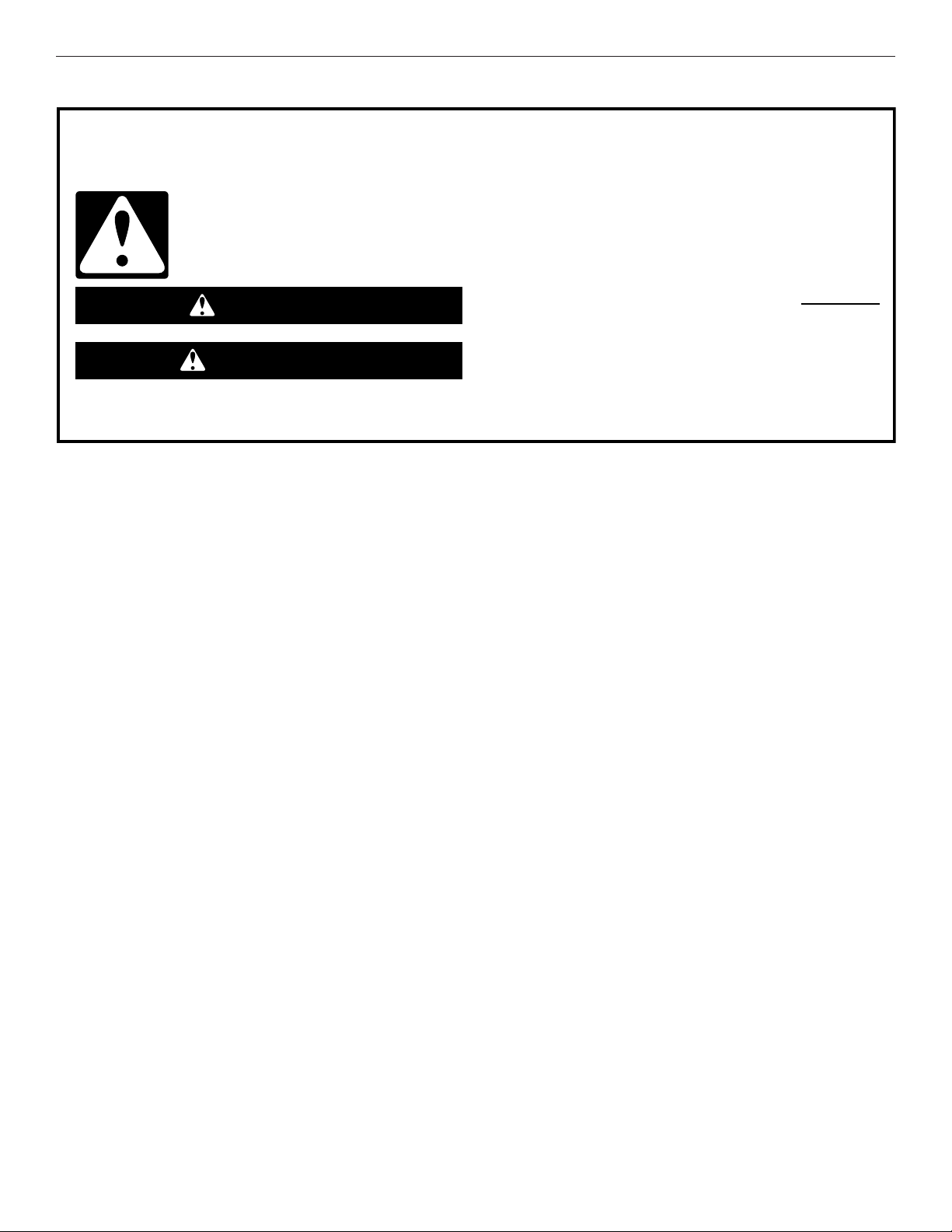
This is the safety alert symbol.
This symbol alerts you to potential hazards that can kill or hurt you and others.
All safety messages will follow the safety alert symbol and either the word “DANGER” or “WARNING.”
These words mean:
You can be killed or seriously injured if you don't immediately
DANGER
WARNING
All safety messages will tell you what the potential hazard is, tell you how to reduce the chance of injury, and tell you what can
happen if the instructions are not followed.
follow instructions.
You
can be killed or seriously injured if you don't
instructions.
follow
3
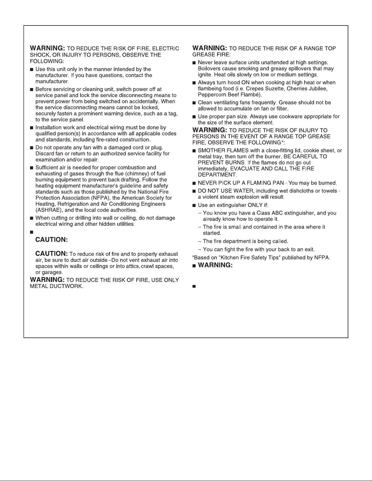
IMPORTANT SAFETY INSTRUCTIONS
Ducted fans must always be vented to the outdoors.
For General Ventilating Use Only. Do Not Use
To Exhaust Hazardous Or Explosive Materials And Vapors.
READ AND SAVE THESE INSTRUCTIONS
To Reduce The Risk Of Fire Or Electric
Shock, Do Not Use This Fan With Any Solid-State Speed
Control Device.
This appliance is not intended for use by people (including
children) whose physical, sensory or mental capacities are
different or impaired or who lack the necessary experience
or knowledge/expertise to do so, unless such persons are
supervised or are trained to operate the appliance by a
person who accepts responsibility for their safety.
4
INSTALLATION REQUIREMENTS
10¾" (27.3 cm)
" (98.4 cm) max.
Tools and Parts
Gather the required tools and parts before starting installation.
Read and follow the instructions provided with any tools listed
here.
Tools Needed
■ Level
■ Drill with 1¼" (3.0 cm), 3/8" (9.5 mm), and 5/16" (7.9 mm)
drill bits
■ Pencil
■ Wire stripper or utility knife
■ Tape measure or ruler
■ Pliers
■ Caulking gun and weatherproof caulking compound
■ Vent clamps
■ Jigsaw or keyhole saw
■ Flat-blade screwdriver
■ Metal snips
■ Phillips screwdriver
Parts Needed
■ Home power supply cable
■ 1/2" (13 mm) UL listed or CSA approved strain relief
■ Three UL Listed wire connectors
For Vented Installations, You Will Also Need:
■ One wall or roof cap
■ Metal vent system
For Non-Vented (Recirculating) Installations, You Will
Also Need:
■ Recirculation Kit Part Number W10692908 for non-vented
(recirculating) installations only. See the “Assistance or
Service” section to order.
■ 6" (15.2 cm) diameter round metal vent duct—length
required is determined by ceiling height.
Parts Supplied
Remove parts from packages. Check that all parts are included.
■ Hood canopy assembly with ventilator and LED and halogen
lights installed
■ Vent transition with back draft dampers installed
■ Metal grease lter(s)—depending on model and size
■ Vent cover support bracket
■ Mounting template
■ Two-piece vent cover
■ Four 4.2 x 8 screws
■ Six 5 x 45 mm mounting screws
■ Two D6.4 x 18 mm washers
■ Two 8 x 40 mm wall anchors
■ Four10 x 60 mm wall anchors
■ Four 5.4 x 75 mm screws (for 10 x 60 mm wall anchors)
■ Two 3.5 x 9.5 mm sheet metal screws
®
■ T10
TORX®† adapter
†®TORX and T10® are registered trademarks of Acument Intellectual Properties, LLC.
Location Requirements
IMPORTANT: Observe all governing codes and ordinances.
Have a qualied technician install the range hood. It is the
installer’s responsibility to comply with installation clearances
specied on the model/serial/rating plate. The model/serial/
rating plate is located behind the left lter on the rear wall of the
vent hood.
Canopy hood location should be away from strong draft areas,
such as windows, doors and strong heating vents.
Cabinet opening dimensions that are shown must be used.
Given dimensions provide minimum clearance.
This range hood is recommended for use with cooktops with a
maximum total rating of 65,000 BTUs or less.
Grounded electrical outlet is required. See the “Electrical
Requirements” section.
The canopy hood is factory-set for venting through the roof
or wall. For non-vented (recirculating) installation see “For
nonvented (recirculating) installation only” in the “Connect Vent
System” section. Recirculation Kit Part Number W10692908 is
available from your dealer or an authorized parts distributor.
All openings in ceiling and wall where canopy hood will be
installed must be sealed.
For Mobile Home Installations
The installation of this range hood must conform to the
Manufactured Home Construction Safety Standards, Title 24
CFR, Part 328 (formerly the Federal Standard for Mobile Home
Construction and Safety, Title 24, HUD, Part 280) or when such
standard is not applicable, the standard for Manufactured Home
Installation 1982 (Manufactured Home Sites, Communities and
Setups) ANSI A225.1/NFPA 501A, or latest edition, or with local
codes.
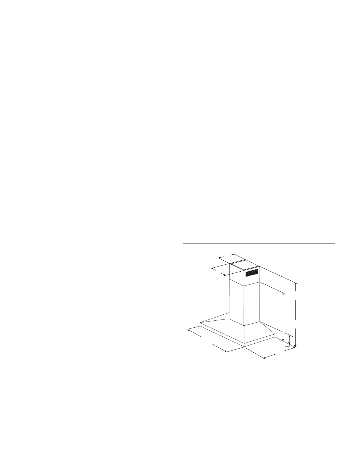
Product Dimensions
13³⁄₁₆" (33.5 cm)
*28⁷⁄₈" (73.4 cm) min.
43³⁄₁₆" (109.7 cm) max.
24"
(60.8 cm)
**25¹⁄₄" (64.1 cm) min.
39¹¹⁄₃₂
30" (76.2 cm)
36" (91.4 cm)
*For non-vented (recirculating) installations
**For vented installations
5"
(12.7 cm)
19¹¹⁄₁₆" (50.0 cm)
5
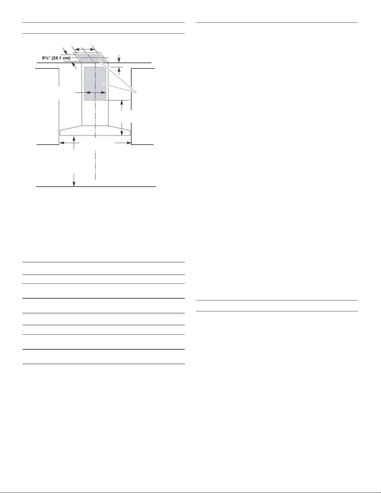
Cabinet Dimensions
10" (25.4 cm) min.
wer
13" (33.0 cm) max.
10" (25.4 cm) min.
13" (33.0 cm) max.
Side
cabinet
30" (76.2 cm) or
36" (91.4 cm)
“X”
bottom of
canopy
to cooking
surface
*For non-vented (recirculating) installations
IMPORTANT:
Minimum distance “X”: 24" (61.0 cm) from electric cooking
surface.
Minimum distance “X”: 27" (68.6 cm) from gas cooking
surfaces.
Suggested maximum distance “X”: 36" (91.4 cm)
The chimneys can be adjusted for different ceiling heights. See
the following chart.
Vented Installations
Min. ceiling height Max. ceiling height
Electric cooking
7' 1" (2.16 m) 9' 3" (2.82 m)
surface
Gas cooking
7' 4" (2.23 m) 9' 3" (2.82 m)
surface
Non-vented (recirculating) Installations
Min. ceiling height Max. ceiling height
Electric cooking
surface
Gas cooking
7' 5" (2.23 m) 9' 7" (2.9 m)
7' 8" (2.33 m) 9' 7" (2.9 m)
surface
NOTE: The range hood chimneys are adjustable and designed to
meet varying ceiling or soft heights depending on the distance
“X” between the bottom of the range hood and the cooking
surface. For higher ceilings, a Chimney Extension Kit is available
from your dealer or an authorized parts distributor. The chimney
extension replaces the chimney shipped with the range hood. To
order, see the “Assistance or Service” section.
2" (5.1 cm) min.
9" (22.9 cm) min.*
17" (43.2 cm)*
Centerline
Cooking surface
Vent and po
supply cable
entry location
Side
cabinet
Venting Requirements
(Vented Models Only)
■ Vent system must terminate to the outdoors except for
non-vented (recirculating) installations.
■ Do not terminate the vent system in an attic or other
enclosed area.
■ Do not use 4" (10.2 cm) laundry-type wall caps.
■ Use metal vent only. Rigid metal vent is recommended.
Plastic or metal foil vent is not recommended.
■ The length of vent system and number of elbows should be
kept to a minimum to provide efcient performance.
For the Most Efcient and Quiet Operation:
■ Use no more than three 90° elbows.
■ Make sure there is a minimum of 24" (61.0 cm) of straight
vent between the elbows if more than one elbow is used.
■ Do not install two elbows together.
■ Use clamps to seal all joints in the vent system.
■ The vent system must have a damper. If the roof or wall
cap has a damper, do not use the damper supplied with the
range hood.
■ Use caulking to seal exterior wall or roof opening around the
cap.
■ The size of the vent should be uniform.
Cold Weather Installations
An additional back draft damper should be installed to minimize
backward cold air ow and a thermal break should be installed
to minimize conduction of outside temperatures as part of the
vent system. The damper should be on the cold air side of the
thermal break.
The break should be as close as possible to where the vent
system enters the heated portion of the house.
Makeup Air
Local building codes may require the use of makeup air systems
when using ventilation systems greater than specied CFM of
air movement. The specied CFM varies from locale to locale.
Consult your HVAC professional for specic requirements in your
area.
Venting Methods
This canopy range hood is factory set for venting through the
roof or through the wall.
A 6" (15.2 cm) round vent system is needed for installation (not
included). The hood exhaust opening is 6" (15.2 cm) round.
NOTE: Flexible vent is not recommended. Flexible vent
creates back pressure and air turbulence that greatly reduce
performance.
Vent system can terminate either through the roof or wall. To
vent through a wall, a 90° elbow is needed.
Rear Discharge
A 90° elbow may be installed immediately above the hood.
6
 Loading...