

KitchenAid KUIA18PNL, KUIA15NRH, KUIA15PLL, KUIS155H, KUIA18NNJ User Manual
...
KAR-14
TECHNICAL EDUCATION
15″ & 18″ AUTOMATIC
ICE MAKERS
KUIS155H,
KUIA15NRH, KUIA15NLH,
KUIA15RRL, KUIA15PLL,
KUIS15NRH, KUIS15PRH
KUIS185J,
KUIA18NNJ, KUIA18PNL,
KUIS18NNJ, KUIS18PNJ,
KUIV18NNM
JOB AID 4317339

FORWARD
This KitchenAid Job Aid “15″ & 18″ Automatic Ice Makers” (Part No. 4317339), provides the
technician with information on the installation, operation, and service of the 15″ & 18″ Automatic
Ice Makers. It is to be used as a training Job Aid and Service Manual. For specific information on
the model being serviced, refer to the “Use and Care Guide,” or “Tech Sheet” provided with the ice
maker.
The Wiring Diagrams and Strip Circuits used in this Job Aid are typical and should be used for
training purposes only. Always use the Wiring Diagram supplied with the product when servicing
the unit.
GOALS AND OBJECTIVES
The goal of this Job Aid is to provide detailed information that will enable the service technician to
properly diagnose malfunctions and repair the KitchenAid 15″ & 18″ Automatic Ice Makers.
The objectives of this Job Aid are to:
• Understand and follow proper safety precautions.
• Successfully troubleshoot and diagnose malfunctions.
• Successfully perform necessary repairs.
• Successfully return the ice maker to its proper operational status.
WHIRLPOOL CORPORATION assumes no responsibility for any repairs made
on our products by anyone other than Authorized Service Technicians.
Copyright © 2003, Whirlpool Corporation, Benton Harbor, MI 49022
- ii -

TABLE OF CONTENTS
Page
GENERAL............................................................................................................................... 1-1
Safety First......................................................................................................................... 1-1
KitchenAid Model & Serial Number Designations—Models Prior To 2003........................ 1-3
KitchenAid Model & Serial Number Designations—Models Starting With 2003 ................ 1-4
Model & Serial Number Label Location ............................................................................. 1-5
Specifications..................................................................................................................... 1-6
KitchenAid Ice Maker Warranty ......................................................................................... 1-7
INSTALLATION INFORMATION ........................................................................................... 2-1
Electrical Supply Requirements ......................................................................................... 2-1
Water Supply And Drain Connections ............................................................................... 2-2
THEORY OF OPERATION ..................................................................................................... 3-1
Operating Systems ............................................................................................................ 3-1
Operational Cycles ............................................................................................................ 3-4
New Ice Maker Control Board (#6100499) ........................................................................ 3-6
Models With Internal Drain Pumps .................................................................................... 3-7
COMPONENT ACCESS ......................................................................................................... 4-1
Component Locations ........................................................................................................ 4-1
Removing The Bin Thermistor, Cutter Grid, Evaporator Thermistor,
& Water Distributor ........................................................................................................ 4-2
Removing The Electronic Control Housing Components .................................................. 4-5
Removing The Water Recirculation Pump......................................................................... 4-7
Removing The Condenser Fan Motor ............................................................................... 4-8
Removing The Evaporator ............................................................................................... 4-11
Removing The Water Inlet Valve ..................................................................................... 4-15
Removing The Hot Gas Valve & Solenoid ....................................................................... 4-16
Removing The Condenser ............................................................................................... 4-17
Removing The Compressor ............................................................................................. 4-18
Removing The Internal Drain Pump ................................................................................ 4-20
Removing The Ice Maker Door & Gasket (15″ Models)................................................... 4-21
Removing The Ice Maker Door & Gasket (18″ Models)................................................... 4-22
COMPONENT TESTING ........................................................................................................ 5-1
Bin Thermistor ................................................................................................................... 5-1
Evaporator Thermistor ....................................................................................................... 5-1
Cutter Grid ......................................................................................................................... 5-2
Cutter Grid Transformer..................................................................................................... 5-2
Water Recirculation Pump ................................................................................................. 5-3
Condenser Fan Motor ........................................................................................................ 5-3
Water Inlet Valve Solenoid ................................................................................................ 5-4
Hot Gas Valve Solenoid..................................................................................................... 5-4
Compressor, Overload Protector, & Relay ........................................................................ 5-5
Pushbutton Switch Assembly ............................................................................................ 5-7
- iii -

Page
DIAGNOSIS & TROUBLESHOOTING ................................................................................... 6-1
Water And Its Effect On Making Ice................................................................................... 6-1
Troubleshooting Chart ....................................................................................................... 6-2
Diagnostic Flow Chart For Ice Maker Control Board #6100499 ........................................ 6-5
WIRING DIAGRAM & STRIP CIRCUITS ............................................................................... 7-1
Wiring Diagram .................................................................................................................. 7-1
Strip Circuits ...................................................................................................................... 7-2
TECH TIPS ............................................................................................................................. 8-1
Cleaning The Ice Maker..................................................................................................... 8-1
Cleaning The Evaporator Plate ...................................................................................... 8-1
Adjusting The Ice Thickness .............................................................................................. 8-3
- iv -

GENERAL
SAFETY FIRST
Your safety and the safety of others is very important.
We have provided many important safety messages in this Job Aid and on the appliance. Always
read and obey all safety messages.
This is the safety alert symbol.
This symbol alerts you to hazards that can kill or hurt you and others.
All safety messages will follow the safety alert symbol and either the word
“DANGER” or “WARNING.” These words mean:
You can be killed or seriously injured if you don’t
DANGER
WARNING
All safety messages will tell you what the potential hazard is, tell you how to reduce the chance
of injury, and tell you what can happen if the instructions are not followed.
immediately follow instructions.
You can be killed or seriously injured if you don’t
follow instructions.
ELECTRICAL POWER SUPPLY &
GROUNDING REQUIREMENTS
WARNING
Electrical Shock Hazard
Disconnect power before servicing.
Replace all parts and panels before
operating.
Failure to do so can result in death or
electrical shock.
WARNING
Electrical Shock Hazard
Plug into a grounded 3-prong outlet.
Do not remove ground prong.
Do not use an adapter.
Do not use an extension cord.
Failure to follow these instructions can
result in death, fire, or electrical shock.
1-1

WARNING
Electrical Shock Hazard
Connect green ground wire to ground
screw.
Failure to do so can result in death or
electrical shock.
IMPORTANT
Electrostatic Discharge (ESD)
Sensitive Electronics
ESD problems are present everywhere.
ESD may damage or weaken the electronic control assembly. The new control
assembly may appear to work well after
repair is finished, but failure may occur at
a later date due to ESD stress.
• Use an antistatic wrist strap. Connect the
wrist strap to the green ground connection point, or to an unpainted metal surface in the appliance.
- OR -
• Touch your finger repeatedly to a green
ground connection point, or to an unpainted metal surface in the appliance.
• Before removing the part from its package, touch the antistatic bag to a green
ground connection point, or to an unpainted metal surface in the appliance.
• Avoid touching electronic parts, or terminal contacts. Handle the electronic control assembly by the edges only.
• When repackaging the failed electronic
control assembly in an antistatic bag,
observe the previous instructions.
1-2

KITCHENAID MODEL & SERIAL NUMBER DESIGNATIONS
MODELS PRIOR TO 2003
MODEL NUMBER
MODEL NUMBER K UI S 15 5 H LS 0
INTERNATIONAL SALES IND.
OR MARKETING CHANNEL
IF PRESENT
PRODUCT GROUP
K = KITCHENAID
PRODUCT IDENTIFICATION
UI = UNDERCOUNTER ICE MAKER
MERCHANDISING SCHEME
A = ARCHITECT
S = STANDARD
CAPACITY / SIZE / SERIES / CONFIGURATION
15 = 15" WIDE
18 = 18" WIDE
FEATURES
5 = 50 POUNDS
YEAR OF INTRODUCTION
H = 1999
COLOR CODE
BL = BLACK; BT = BISCUIT; BS = BLACK & STAINLESS STEEL
LS = LEFT SWING STAINLESS ARCHITECT
RS = RIGHT SWING STAINLESS ARCHITECT
PB = BLACK W/PUMP
PW = WHITE W/PUMP
WH = WHITE
ENGINEERING CHANGE (NUMERIC)
SERIAL NUMBER
SERIAL NUMBER E M 0 4 54321
DIVISION RESPONSIBILITY
E = EVANSVILLE, IN
YEAR OF PRODUCTION
M = 2002, P = 2003
WEEK OF PRODUCTION
04 = 4th WEEK
PRODUCT SEQUENCE NUMBER
1-3

KITCHENAID MODEL & SERIAL NUMBER DESIGNATIONS
MODELS STARTING WITH 2003
MODEL NUMBER
MODEL NUMBER K UI S 15 NR H S 0
INTERNATIONAL SALES IND.
OR MARKETING CHANNEL
IF PRESENT
PRODUCT GROUP
K = KITCHENAID
PRODUCT IDENTIFICATION
UI = UNDERCOUNTER ICE MAKER
MERCHANDISING SCHEME
A = ARCHITECT
S = STANDARD
V = SIGNATURE SERIES
CAPACITY / SIZE / SERIES / CONFIGURATION
15 = 15" WIDE
18 = 18" WIDE
FEATURES
PR = PUMP, RIGHT HAND DOOR SWING
PL = PUMP, LEFT HAND DOOR SWING
PN = PUMP, NON-REVERSIBLE DOOR SWING
NR = NON-PUMP, RIGHT HAND DOOR SWING
NL = NON-PUMP, LEFT HAND DOOR SWING
NN = NON-PUMP, NON-REVERSIBLE DOOR SWING
YEAR OF INTRODUCTION
H = 1999, J = 2000, K = 2001, L = 2002, M = 2003
COLOR CODE
B = BLACK, W = WHITE, S = STAINLESS
T = BISCUIT, M = METEORITE
ENGINEERING CHANGE (NUMERIC)
SERIAL NUMBER
SERIAL NUMBER E P 04 54321
DIVISION RESPONSIBILITY
E = EVANSVILLE, IN
YEAR OF PRODUCTION
P = 2003, R = 2004
WEEK OF PRODUCTION
04 = 4th WEEK
PRODUCT SEQUENCE NUMBER
1-4
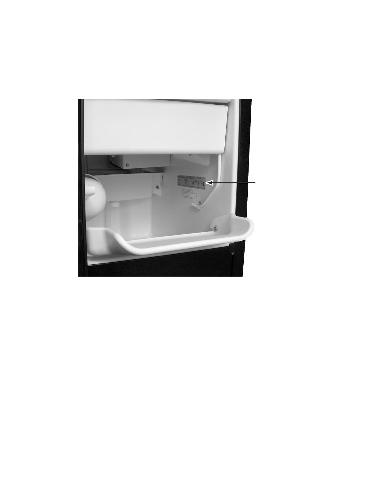
MODEL & SERIAL NUMBER LABEL LOCATION
The Model/Serial Number label location is shown below.
Model & Serial
Number Location
1-5
SPECIFICATIONS
AC Power Supply ...........................................................97 to 127 VAC (rated 115VAC), 60 Hz
Amperage .......................................................................................................... 3.6 Amps (max)
Minimum Circuit Capacity ............................................................................................ 15 Amps
Ice Production per 24 hours (Approximate) ................................................................................
Ambient Temperature
70°F (21°C) 46 lbs (21 kg)
80°F (27°C) 47 lbs (21 kg)
90°F (32°C) 40 lbs (18 kg)
100°F (38°C) 40 lbs (18 kg)
110°F (43°C) 38 lbs (17 kg)
Ice Shape ...................................................................................................... 3/4″ x 3/4″ Square
Ice Thickness @ Normal Setting (Approximate) .................................................0.32″ (8.1 mm)
Ice Thickness @ Thin Setting (Approximate) ...................................................... 0.28″ (7.0 mm)
Ice Thickness @ Thick Setting (Approximate) ................................................... 0.39″ (9.9 mm)
Storage Capacity (Approximate) ....................................................................... 24 lbs. (10.9 kg)
Exterior Dimensions (W x D x H) .....15″ or 18″ x 24″ x 34″ (381 or 457.2 x 609.6 x 863.6 mm)
Exterior Finish .......................................................................... Stainless Steel or Painted Steel
Net Weight ................................................... 15″ = 94 lbs. (42.6 kg) 18″ = 123 lbs. (55.8 kg)
Cube Thickness Control ......................... Thermistor under Evaporator & Control Board Setting
Harvest Control ...................................... Thermistor under Evaporator & Control Board Setting
Bin Ice Level Control ...........................................................................Thermistor on side of Bin
Refrigerant ....................................................................................................................... R134a
Ambient Temperature .............................................................................................. 55 to 100°F
Water Pressure .................................................................................................... 20 to 120 psig
Water Consumption (Dependent On Water Pressure)..................... 6 to 10 gallons per 4 hours
Water Temperature
60°F (15°C)
1-6

KITCHENAID ICE MAKER WARRANTY
1-7

— NOTES —
1-8

INSTALLATION INFORMATION
ELECTRICAL SUPPLY REQUIREMENTS
WARNING
Electrical Shock Hazard
• A 115 Volt, 60 Hz, AC only 15 ampere electrical
supply, properly grounded in accordance
with the National Electrical Code and local
codes and ordinances, is required.
• It is recommended that a separate circuit,
serving only the ice maker, be provided. Use
a receptacle which cannot be turned off by a
switch or pull chain.
Plug into a grounded 3 prong outlet.
Do not remove ground prong.
Do not use an adapter.
Do not use an extension cord.
Failure to follow these instructions can
result in death, fire, or electrical shock.
Before you move the ice maker into its final
location, it is important to make sure you have
the proper electrical connection:
Recommended Grounding Method
For personal safety, this appliance must be
grounded. This appliance is equipped with a
power supply cord having a 3-prong grounding
plug. To minimize possible shock hazard, the
cord must be plugged into a mating, 3- prong,
grounding-type wall receptacle, grounded in
accordance with the National Electrical Code
and local codes and ordinances. If a mating
wall receptacle is not available, it is the personal responsibility of the customer to have a
properly grounded, 3-prong wall receptacle
installed by a qualified electrician.
2-1
WATER SUPPLY AND DRAIN CONNECTIONS
CONNECTING THE WATER LINE
1. Turn off the main water supply.
2. Turn on the nearest faucet and allow it to
run long enough to clear line of water.
3. Find a 1/2″ (12.70 mm) to 1-1/4″ (3.18 cm)
vertical cold water pipe near the ice maker.
NOTE: A horizontal pipe will work, but drill on
the top side of the pipe, not the bottom. This will
keep water away from the drill motor, and also
keeps normal sediment from collecting in the
valve.
4. Using a grounded drill, drill a 1/4″ (6.35 mm)
hole in the cold water pipe you have selected.
5. Fasten a shutoff valve to the cold water
pipe with a pipe clamp. Make sure that the
outlet end is firmly in the 1/4″ (6.35 mm)
drilled hole, and that the washer is under
the pipe clamp.
IMPORTANT: Do not use a piercing-type, or a
3/16″ (4.76 mm) saddle-type valve. These can
reduce water flow and easily become clogged.
8. Use 1/4″ (6.35 mm) O.D. copper tubing for
the cold water supply and:
a)Measure from the connection at the
back of the ice maker to the cold water
pipe.
b)Add an extra 36″ (91.4 cm) to ensure
that you have the proper length. Make
sure both ends of the copper tubing are
cut square.
c) Slip a compression sleeve and com-
pression nut over the ends of the copper tubing.
d)Insert the end of tubing into the water
shutoff outlet as far as it will go, and
screw the compression nut onto the
outlet. Tighten the compression nut with
an adjustable wrench, but do not overtighten it.
9. Place the free end of the copper tubing
into a container or sink, and turn on the
main water supply. Flush the tubing until
water is clear, and then turn off the shutoff
valve on the water pipe. NOTE: Always
drain the water line before making the final
connection to the inlet of the water valve to
prevent a possible water valve malfunction.
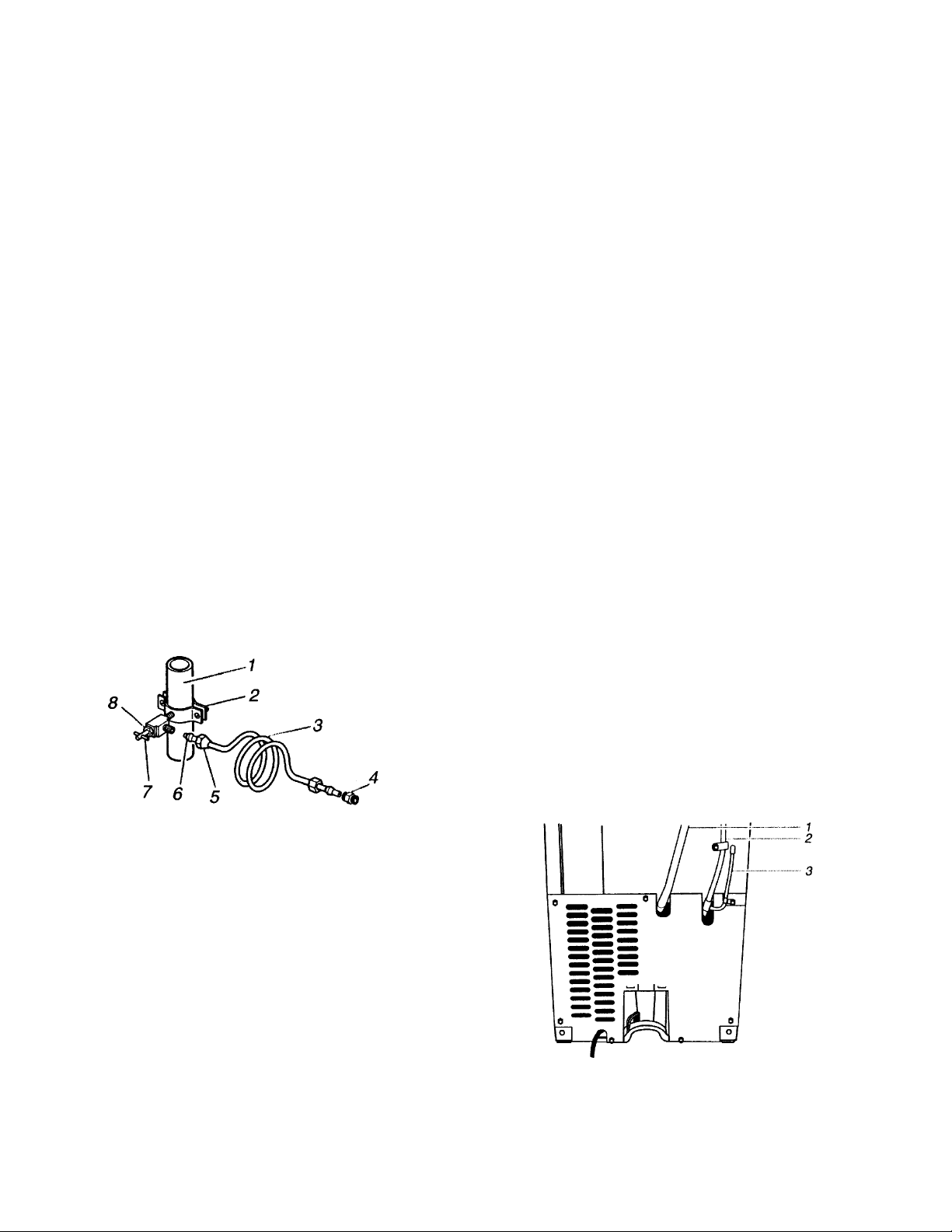
1. Cold Water Pipe 5. Compression Nut
2. Pipe Clamp 6. Compression Sleeve
3. Copper Tubing 7. Shutoff Valve
4. Coupling (purchased) 8. Packing Nut
6. Tighten the packing nut.
7. Tighten the pipe clamp screws carefully
and evenly so that the washer makes a
watertight seal. Do not overtighten the
pipe clamp. If the water line is soft copper
tubing, you could crush it.
10. Bend the copper tubing to meet the water
line inlet, located on the back of the ice
maker cabinet, as shown below.
1. Drain Hose (Drain Pump models only)
2. Vent Hose (Drain Pump models only)
3. Water Supply Line
2-2
11. Thread the nut onto the coupling at the
end of the copper tubing. Tighten the nut
by hand. Then tighten it with a wrench two
more turns. Do not overtighten.
CONNECTING THE DRAIN
Gravity Drain System
Connect the ice maker drain so that it is in
accordance with all state and local codes and
ordinances. If the ice maker is provided with a
gravity drain system, use the following guidelines when installing the drain lines. This will
prevent water from flowing back into the ice
maker storage bin and onto the floor, causing
water damage.
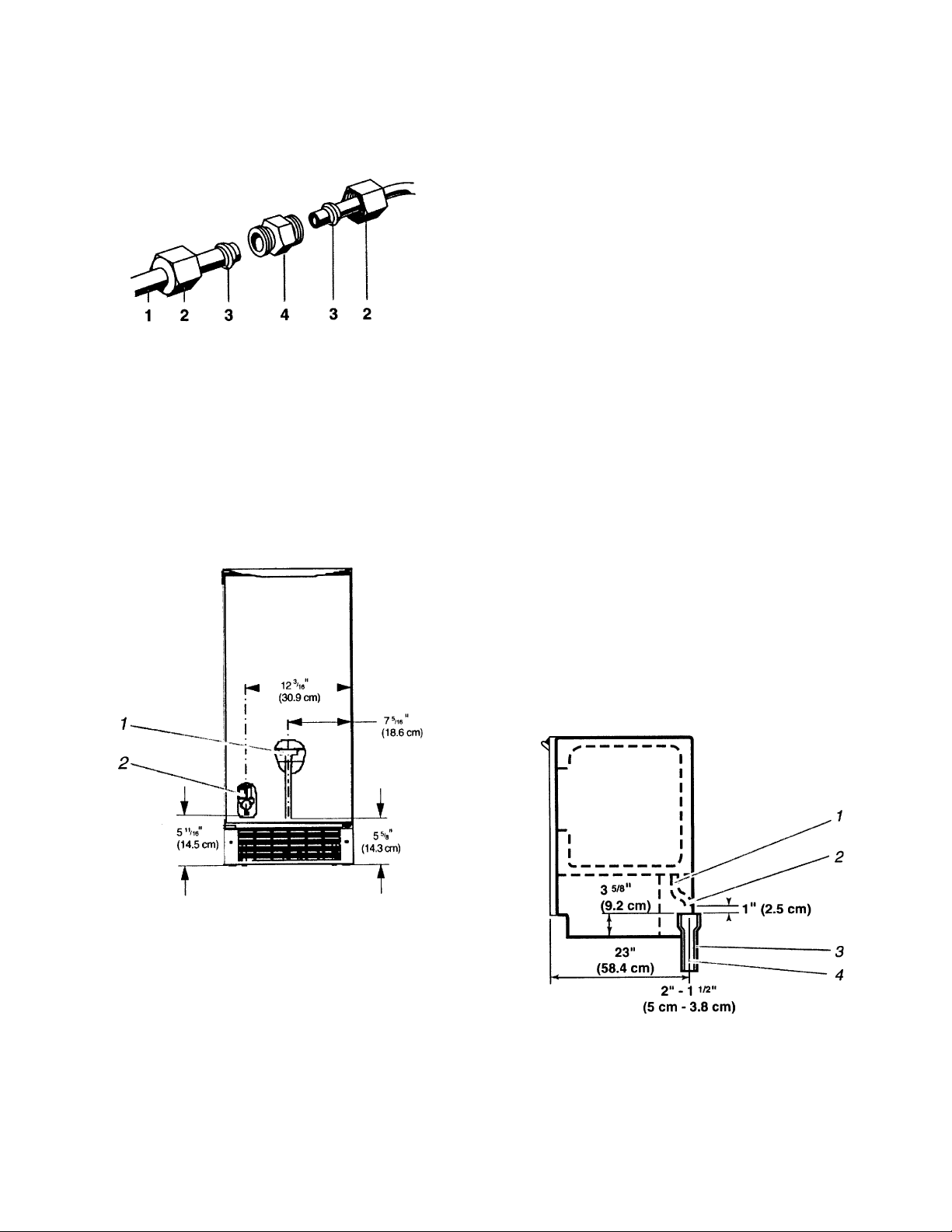
1. Line to ice maker 3. Ferrule (purchased)
2. Nut (purchased) 4. Coupling (purchased)
12. Remove the four screws from the lower
access panel and remove the panel from
the front of the ice maker.
NOTE: To prevent rattling, keep the copper
tubing from touching the cabinet side wall, or
any other parts inside the cabinet.
FRONT VIEW
• Drain lines must have a minimum of 5/8″
(15.88 mm) inside diameter.
• Drain lines must have a 1″ drop per 48″ (2.54 cm
drop per 122 cm) of run, or 1/4″ drop per 12″
(6.35 mm per 30.48 cm) and not have any
low points where water can settle.
• The floor drains must be large enough to
accommodate drainage from all drains.
• The ideal installation has a standpipe with a
1-1/2″ (3.81 cm) to 2″ (5.08 cm) PVC drain
reducer installed directly below the outlet of
the drain tube, as shown. You must maintain
a 1″ (2.54 cm) air gap between the drain
hose and the standpipe.
• It may be desirable to insulate the drain line
up to the drain inlet.
SIDE VIEW
1. Water Pan Drain
2. Water Valve
13. Turn the shutoff valve ON.
14. Check the water connections for leaks,
and carefully tighten any that are leaking.
15. Reinstall the lower access panel with its
four screws.
1. Drain Hose
2. 1″ (2.54 cm) Air Gap
3. PVC Drain Reducer
4. Center of drain should be 23″ (58.4 cm) from
front of door, with or without the 3/4″ (1.91 cm)
panel on the door.
2-3

After ensuring that the drain system is adequate, use the following steps to properly
place the ice maker:
1. Plug in the ice maker or reconnect power.
Drain Pump System (On Some Models)
Connect the drain pump hose (provided with
the product) to the drain in accordance with all
state and local codes and ordinances.
2. Recheck the ice maker and make sure
that it is level.
3. Push the ice maker into position so that
the drain tube is positioned over the PVC
drain reducer.
4. If it is required by the local sanitation code,
seal the cabinet to the floor with an approved caulking compound after all water
and electrical connections have been
made.
NOTE: If the drain hose becomes twisted and
water cannot drain, the ice maker will not operate.
2-4

THEORY OF OPERATION
OPERATING SYSTEMS
There are three operating systems in the ice
maker:
• Refrigeration System
• Water System
• Electrical System
REFRIGERATION SYSTEM
The refrigeration system in the ice maker is
very similar to the system used in other refrigeration appliances. The refrigerant used in this
unit is R134a.
There are two very important additions to the
refrigeration system in the ice maker: the Hot
Gas Valve, and the Condenser Accumulator
Tube. The components operate as follows:
• Hot Gas Valve - Allows high pressure
refrigerant gas to bypass the condenser
and flow through the condenser accumulator tube.
• Condenser Accumulator Tube - Hot gas
pushes liquid refrigerant through the accumulator tube into the evaporator,
helping to evenly heat the evaporator
plate so that the ice slab releases
quickly and evenly.
3-1

WATER SYSTEM
The water system provides:
• Fresh water for ice production
• Water recirculation as ice is produced
The water system also flushes away minerals
and contaminates, circulates cleaning solution
during the clean cycle, and provides drainage.
The hardness of the water supplied to the ice
maker will affect the quality of the ice that is
produced. It may also affect the operation of
the water system.
Water Distributor
Evaporator
A water softener, or polyphosphate feeder, will
not cure all of the problems associated with
hard water, but they can be used to reduce
scale buildup in the ice maker. NOTE: Some
polyphosphate feeders will cause a slime
buildup in the water system when the water
supply has a low mineral content.
The ice maker’s water system is shown below.
Reservoir Pan
Water
Inlet Tube
Water
Inlet Valve
Cutter Grid
Water Pump
Outlet Tube
Bin Water Inlet Tube
Water Pump
Reservoir Drain
Standpipe
To Bin Drain
From Water Supply
3-2

ELECTRICAL SYSTEM
The ice maker’s electrical system provides
power for the refrigeration and water systems,
and controls the operational cycling.
3-3

OPERATIONAL CYCLES
There are three main operational cycles for the
ice maker (more detailed operation is found in
the flow chart on page 6-5):
• Ice Making
• Harvest
• Diagnostics/Clean
ICE MAKING CYCLE
In addition, there are two possible “Off” cycles
for the ice maker. They occur when:
1. The bin is full of ice and the service
control switch is turned “ON” (Idle
mode).
2. The service control switch is turned
“OFF” while power is still supplied to
the unit.
Electrical System
Power is supplied through the service control
switches to the primary side of the voltage
step-down transformer, (120 VAC reduced to
8.7 VAC for the cutter grid and the bin light),
and the electronic control board. The electronic control board in turn supplies 120 VAC to
the water recirculating pump, water inlet valve,
hot gas solenoid, condenser fan motor, and
compressor. An evaporator thermistor supplies temperature information to the electronic
control.
Refrigeration System
The hot gas refrigerant, under high pressure, is
forced through the condenser, where it changes
into a liquid, and flows through the drier and
capillary tube into the evaporator. Under low
pressure in the evaporator, the liquid refrigerant absorbs heat from the water flowing over
the evaporator. The refrigerant evaporates into
a gas, and passes into the accumulator. As a
low pressure gas, the refrigerant flows back
through the suction line of the heat exchanger,
to the compressor.
During the Ice Making cycle, some of the hot
gas that is in the condenser accumulating tube,
condenses to a liquid, and remains in the
accumulating tube.
During the later stages of the Ice Making cycle,
as the ice slab forms on the evaporator freezing plate, some of the refrigerant passing
through the evaporator will not evaporate into
a gas, but will remain a liquid. This liquid
refrigerant will settle in the accumulator, while
the refrigerant vapor is sucked off through the
suction tube at the top of the accumulator. This
accumulated liquid refrigerant will eventually
be evaporated by the warmed refrigerant gas
passing through the accumulator during the
Harvest cycle, and during the beginning of the
next Ice Making cycle.
NOTE: It is very important that the accumulator
is not tilted out of a horizontal position. If
moved, it could cause compressor failure.
Water System
The water recirculating pump moves the water
from the reservoir pan up to the distributor,
where it flows out over the evaporator freezing
plate.
Water that does not freeze on the evaporator
plate runs off the front edge, and falls back into
the reservoir, where it is recirculated back to
the water distributor.
As the ice slab forms, the minerals in the water
are on the surface of the ice. The water flowing
over the top of the ice slab washes these minerals back into the water reservoir pan. The water
continues to recirculate until the ice slab reaches
the set thickness. Thickness is determined by
the placement of the P4 jumper, located on the
control board.
Control board #6100499 with Code Date MGR/
0245 (45th week, 2002), or higher, will allow ice
thickness adjustments (see “Adjusting The Ice
Thickness” on page 8-3).
3-4

HARVEST CYCLE
Electrical System
When the set temperature of the evaporator
thermistor is reached, it signals the electronic
control to terminate power to the condenser
fan, and the water recirculating pump. Power is
then supplied to the hot gas valve and water fill
valve solenoids.
If the evaporator thermistor is unplugged, the
control defaults to the maximum freeze and
harvest times.
Refrigeration System
The hot gas valve opens, allowing high pressure refrigerant gas to bypass the condenser,
and flow through the condenser accumulating
tube. The hot gas pushes the liquid refrigerant
that has accumulated in the accumulator tube
up into the evaporator. The hot liquid refrigerant evenly heats the evaporator plate so that
the ice slab releases quickly and evenly.
The ice slab, when released, slides off of the
evaporator plate onto the cutter grid.
Water System
The water valve opens, allowing water to flow
into the water reservoir pan. As the reservoir
fills, the mineral-laden water from the previous
Ice Making cycle, is flushed out the overflow
tube.
As a result of the hot gas flow and the ice sliding
off the evaporator plate, the evaporator temperature begins to rise. When the evaporator
thermistor reaches the set temperature (6.5°F),
the unit switches to the Ice Making cycle. This
cycling between Ice Making and Harvest, continues until the ice bin is full.
The electronic control board controls the various components and systems in the ice maker
for each of the Ice Making and Harvest cycles.
When the ice maker’s service control switch is
in the “On” position, and the bin is not full of ice,
the evaporator thermistor determines whether
the unit will be in the Ice Making, or the Harvest
cycle.
If the thermistor is unplugged from the control
board, the unit will cycle using maximum freeze
and harvest times.
DIAGNOSTICS / CLEAN CYCLE
Electrical System
Power is supplied to the electrical components
through the service control switch.
The electronic control board controls the various components and systems during the Diagnostics/Clean cycle. During the first 25 seconds of the cycle, each component will operate
for 5 seconds.
For the order of the components cycled, see
the flow chart on page 6-5.
Water System
When the service control switch is in the ‘’Clean”
position, the water recirculating pump circulates the cleaning solution that has been added
to the reservoir, up to the water distributor,
across the evaporator, and back into the reservoir, where it is recirculated.
3-5

NEW ICE MAKER CONTROL BOARD (#6100499)
NOTE: Due to a quality improvement, the new
control board will replace the older design
(#2185947).
If you are replacing control board #2185947,
please read the improvements listed below. If
you are replacing control board #6100499, you
may disregard the following information.
There are no differences in mounting or wiring
the new control board. Improvements were
made to support low voltage applications.
Additional improvements include the following:
• A 15-minute minimum, and 25-minute
maximum, ice making cycle time limit.
This eliminates the production of ice slabs
that are too thin or too thick. Control
boards with Code Date MGR/0245, (45th
week, 2002), or higher, will allow ice
thickness adjustments by moving the
jumper at P4 (see “Adjusting The Ice
Thickness” on page 8-3).
• During a harvest, the water valve “on
time” is now limited to 1 minute to reduce
water usage. This also eliminates the
condition of the water valve being energized for an unlimited amount of time if
the evaporator thermistor is not located
correctly, or if the reversing valve has
failed or is unplugged. If the evaporator
thermistor is unplugged, a 25-minute default freeze, and 4-minute harvest interval will occur.
If the unit stays in harvest mode for more
than 16 minutes, the unit will go into a
failure mode, shutting the unit down, and
flashing the LED light. To get out of failure
mode, shut the unit off, and then back on
again. This will reset the control board. If
the failure was not corrected, the unit will
return to failure mode when the unit
reaches it’s 16-minute cycle again. If this
occurs, find the cause of the failure, and
repair it, then unplug the unit to reset the
board.
• The diagnostic mode sequence was
changed, moving the bin and evaporator
thermistor checks to the beginning of the
sequence. The old boards had these
checks at the end of the sequence.
• Whenever the unit has reached a failure
mode, the LED will flash, and the unit will
shut down. If the failure was caused during a harvest cycle which lasted more
than 16 minutes, the LED will remain
flashing on & off in half-second increments. If the failure is caused by a faulty
bin thermistor, (not detected), the LED
will remain flashing on & off in 1-second
increments. These are the only two failures that cause the unit to reach a shutdown failure mode.
• During the Clean cycle, the control board
performs the diagnostics first. If the bin
thermistor is not detected, the LED will
flash two times. This is followed by a
3-second delay. If the evaporator thermistor is not detected, the LED will flash
on five times. This will be followed by a
3-second delay. The LED will then come
back on, and remain on for the remainder
of the Clean cycle, and until the unit is
turned back on.
The following check can be done on the
board & thermistors:
- Unplug either thermistor electrical
connection.
- Press the Clean switch. The LED
should flash as described above, depending upon which thermistor is unplugged, or if both are unplugged.
For step-by-step operation, see the flow chart
on page 6-5.
3-6

MODELS WITH INTERNAL DRAIN PUMPS
The power cord on the internal drain pump is
connected to a 120 VAC wall outlet. The ice
maker is then connected to the 120 VAC outlet
on the drain pump. If the drain pump fails, or if
the drain becomes blocked, power is shut off to
the 120 VAC outlet on the drain pump.
When the unit is first plugged in, the drain pump
will run for 20 seconds. The power can be
disconnected and reconnected to verify that
the pump is operating properly.
Water from the ice maker reservoir, or melting
ice from the bin, drains down the bin drain tube
Pump Inlet
Overfill Contact
Full Contacts
Vent Outlet
into the pump inlet, and then into the drain
pump chamber. As the water level rises, it
bridges the “full” contacts, and the pump starts
to run. The pump discharges the water through
the outlet and the check valve. When the “full”
connection is removed, the pump runs for an
additional 12 seconds to empty the tank.
If the water level in the drain pump continues to
rise, due to a slow or blocked drain, or a
blocked vent hose, and touches the “overfill”
contact, power will be turned off to the drain
pump’s 120 VAC outlet, causing the ice maker
to turn off.
White
Black
Green
Pump Outlet &
Check Valve
Contacts Sense Continuity
Through The Water
Screen
Washer
Connector Hose
(Contains Screen Washer)
3-7

— NOTES —
3-8
 Loading...