

KitchenAid KUIC15NHZS, KUIC15PHZS, KUIC18NNZS, KUIC18PNZS, KUIS15NNZB Installation Instructions
...
ICE MAKER INSTALLATION INSTRUCTIONS
W10541636C
You can be killed or seriously injured if you don't immediately
You
can be killed or seriously injured if you don't
follow
All safety messages will tell you what the potential hazard is, tell you how to reduce the chance of injury, and tell you what can
happen if the instructions are not followed.
Your safety and the safety of others are very important.
We have provided many important safety messages in this manual and on your appliance. Always read and obey all safety
messages.
This is the safety alert symbol.
This symbol alerts you to potential hazards that can kill or hurt you and others.
All safety messages will follow the safety alert symbol and either the word “DANGER” or “WARNING.”
These words mean:
follow instructions.
instructions.
DANGER
WARNING
IMPORTANT SAFETY INSTRUCTIONS
WARNING
:
To reduce the risk of fire, electric shock, or injury when using your ice maker, follow these basic
precautions
:
SAVE THESE INSTRUCTIONS
■ Plug into a grounded 3 prong outlet.
■ Do not remove ground prong.
■ Do not use an adapter.
■ Do not use an extension cord.
■ Disconnect power before manually cleaning the inside components.
■ Disconnect power before servicing.
■ Replace all parts and panels before operating.
■ Use two or more people to move and install ice maker.
INSTRUCTIONS D’INSTALLATION DE
MACHINE À GLAÇONS
Table of Contents/Table des matières
ICE MAKER SAFETY...................................................................................1
INSTALLATION INSTRUCTIONS ............................................................... 2
Unpack the Ice Maker...............................................................................2
Location Requirements.............................................................................2
Electrical Requirements............................................................................3
Water Supply Requirements.....................................................................3
Vacation or Extended Time Without Use .................................................3
Connect Water Supply..............................................................................3
Drain Pump Installation............................................................................. 4
Drain Connection ...................................................................................... 7
Door Reversal—Side Swing Only............................................................. 8
Leveling...................................................................................................10
Cleaning .................................................................................................. 10
ICE MAKER SAFETY
SÉCURITÉ DE LA MACHINE À GLAÇONS............................................. 12
INSTRUCTIONS D’INSTALLATION .........................................................13
Déballage de la machine à glaçons ....................................................... 13
Exigences d’emplacement .....................................................................13
Spécifications électriques....................................................................... 13
Spécifications de l’alimentation en eau.................................................. 14
Vacances ou longue période d’inutilisation ........................................... 14
Raccordement à la canalisation d’eau...................................................14
Installation de la pompe de vidange ......................................................15
Raccordement au conduit vidange........................................................18
Inversion du sens d’installation de la porte —
Porte à ouverture latérale uniquement................................................... 19
Nivellement ............................................................................................. 21
Nettoyage ............................................................................................... 22
INSTALLATION INSTRUCTIONS
State of California Proposition 65 Warnings:
WARNING: This product contains one or more chemicals known to the State of California to cause cancer.
WARNING: This product contains one or more chemicals known to the State of California to cause birth defects or other
reproductive harm.
WARNING
Excessive Weight Hazard
Use two or more people to move and install ice maker.
Failure to do so can result in back or other injury.
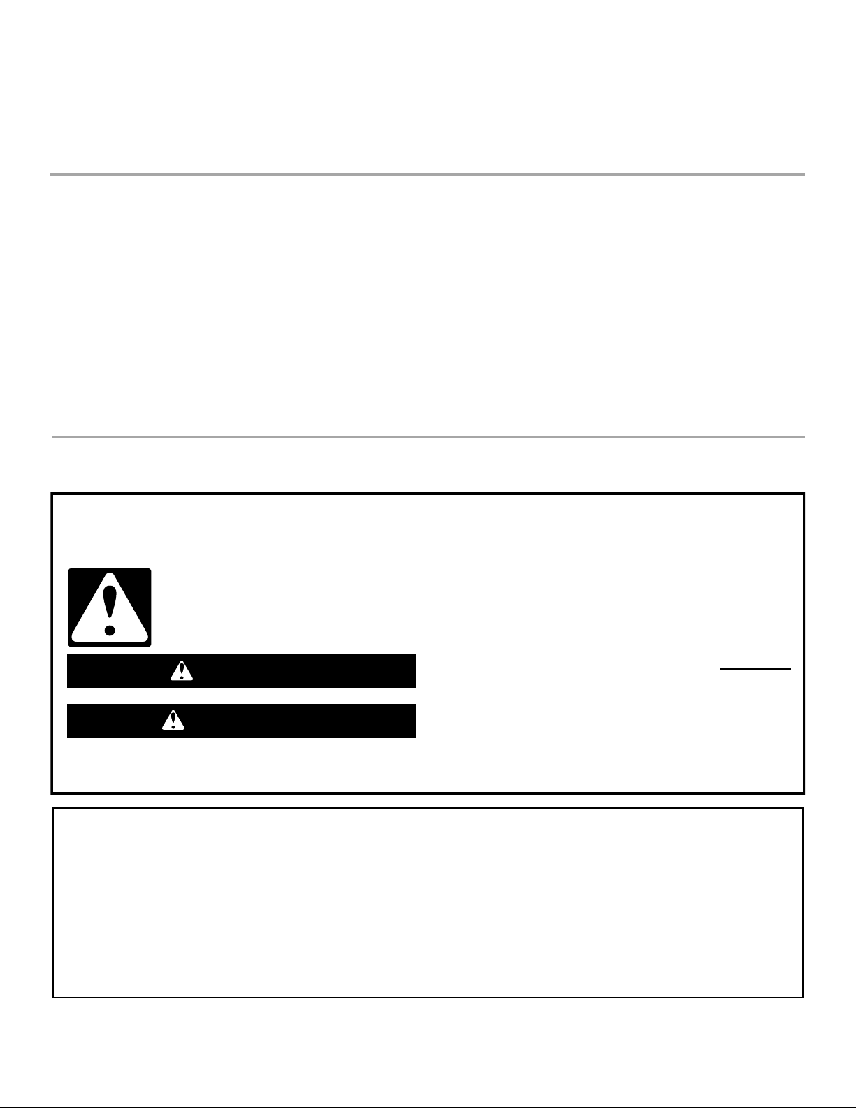
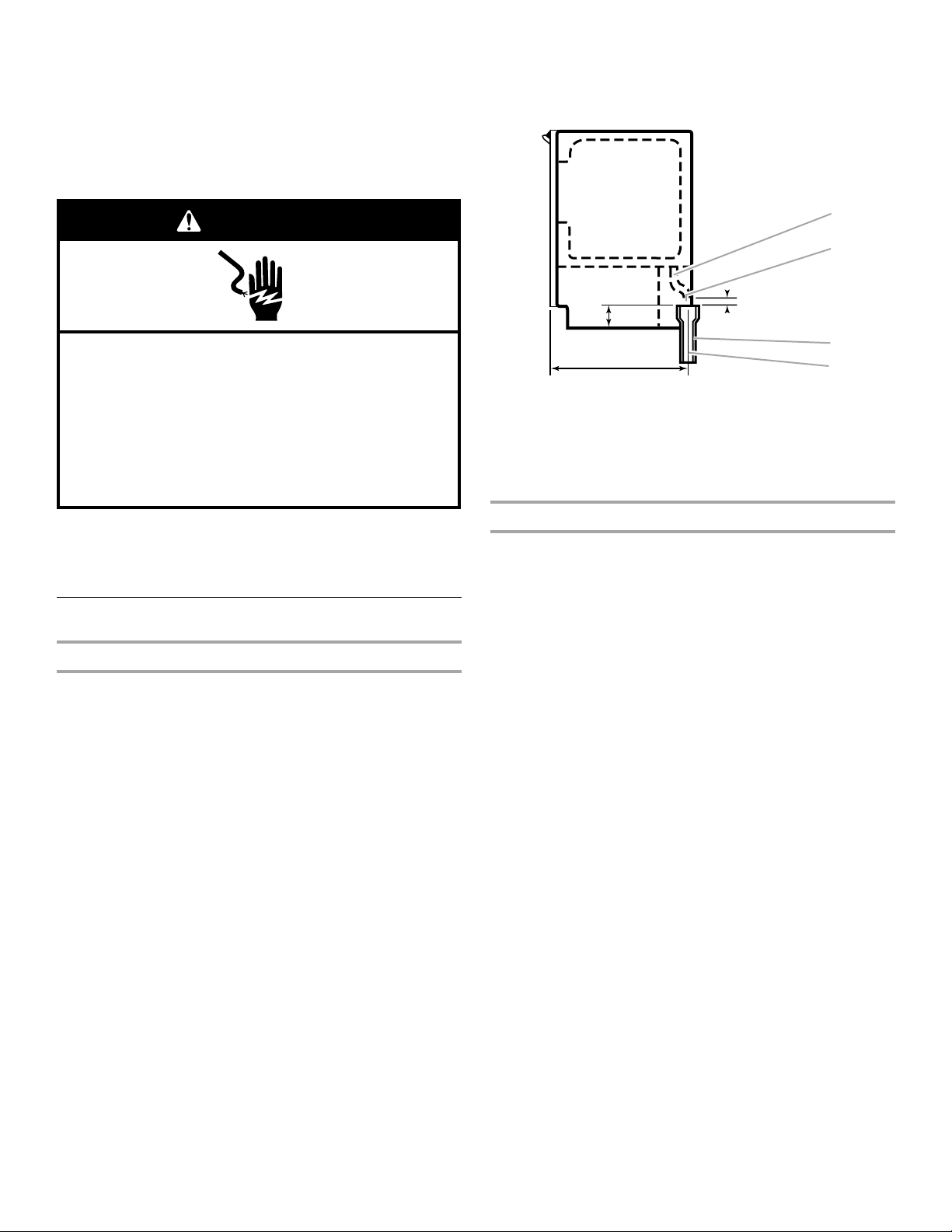
3¹⁄₂"
(8.9 cm)
9"
(22.9 cm)
11¹⁄₂"
(29.2 cm)
24"
(60.1 cm)
34"
(86.4 cm)
Min.
34
¹⁄₂"
(87.6 cm)
Max.
B
A
28¹⁄₂"
(72.4 cm)
C
Unpack the Ice Maker
Removing Packaging Materials
Remove tape and glue from your ice maker before using.
■ To remove any remaining tape or glue from the exterior of the
ice maker, rub the area briskly with your thumb. Tape or glue
residue can also be easily removed by rubbing a small amount
of liquid dish soap over the adhesive with your fingers. Wipe
with warm water and dry.
■ Do not use sharp instruments, rubbing alcohol, flammable
fluids, or abrasive cleaners to remove tape or glue. Do not use
chlorine bleach on the stainless steel surfaces of the ice
maker. These products can damage the surface of your
ice maker.
Cleaning Before Use
■ The ice maker must be installed in an area sheltered from the
elements, such as wind, rain, water spray, or drip.
■ When installing the ice maker under a counter, follow the
recommended opening dimensions shown. Place electrical
and plumbing fixtures in the recommended location as shown.
NOTES:
■ Check that the power supply cord is not damaged, or
pinched or kinked between the ice maker and the cabinet.
■ Check that the water supply line is not damaged, or
pinched or kinked between the ice maker and the cabinet.
■ Check that the drain line (on some models) is not
damaged, or pinched or kinked between the ice maker
and the cabinet.
■ Check that the ice maker door is not flush with the front of
standard cabinets to avoid problems with opening the ice
maker door.
After you remove all of the packaging materials, clean the inside of
your ice maker before using it. See the cleaning instructions in the
“Ice Maker Care” section.
Location Requirements
■ To ensure proper ventilation for your ice maker, the front side
must be completely unobstructed. The ice maker may be
closed-in on the top and three sides, but the installation
should allow the ice maker to be pulled forward for servicing if
necessary.
■ Installation of the ice maker requires a cold water supply inlet
of ¹⁄₄" (6.35 mm) OD soft copper tubing with a shutoff valve or
a Whirlpool supply line Part Number W10505928RP, and a
Whirlpool approved drain pump, Part Number 1901A, only to
carry the water to an existing drain.
■ Choose a well ventilated area with temperatures above 55°F
(13°C) and below 110°F (43°C). Best results are obtained
between 70°F and 90°F (21ºC and 32°C).
2
A. Recommended location for electrical
and plumbing fixtures
B. Floor level
■ Choose a location where the floor is even. It is important for
the ice maker to be level in order to work properly. If needed,
you can adjust the height of the ice maker by changing the
height of the leveling legs. See “Leveling.”
C. 15" or 18" (38.1 cm or
45.7 cm) depending on
model

Electrical Requirements
Electrical Shock Hazard
Plug into a grounded 3 prong outlet.
Do not remove ground prong.
Do not use an adapter.
Do not use an extension cord.
Failure to follow these instructions can result in death,
fire, or electrical shock.
WARNING
Before you move your ice maker into its final location, it is
important to make sure you have the proper electrical connection:
A 115 volt, 60 Hz., AC only, 15- or 20-amp electrical supply,
properly grounded in accordance with the National Electrical
Code and local codes and ordinances, is required.
It is recommended that a separate circuit, serving only your ice
maker, be provided. Use a receptacle which cannot be turned off
by a switch or pull chain.
IMPORTANT: If this product is connected to a GFCI (Ground Fault
Circuit Interrupter) equipped outlet, nuisance tripping of the power
supply may occur, resulting in loss of cooling. Ice quality may be
affected. If nuisance tripping has occurred, and if the condition of
the ice appears poor, dispose of it.
Recommended Grounding Method
The ice maker must be grounded. The ice maker is equipped with
a power supply cord having a 3 prong grounding plug. The cord
must be plugged into a mating, 3 prong, grounding-type wall
receptacle, grounded in accordance with the National Electrical
Code and local codes and ordinances. If a mating wall receptacle
is not available, it is the personal responsibility of the customer to
have a properly grounded, 3 prong wall receptacle installed by a
qualified electrician.
Water Supply Requirements
Check that the water supply lines are insulated against freezing
conditions. Ice formations in the supply lines can increase water
pressure and damage your ice maker or home. Damage from
frozen supply lines is not covered by the warranty.
A cold water supply with water pressure of between 30 and
120 psi (207 and 827 kPa) is required to operate the ice maker. If
you have questions about your water pressure, call a licensed,
qualified plumber.
Reverse Osmosis Water Supply
IMPORTANT:
■ A reverse osmosis water filtration system is not recommended
for ice makers that have a drain pump installed.
■ For gravity drain systems only.
■ The pressure of the water supply coming out of a reverse
osmosis system going to the water inlet valve of the ice maker
needs to be between 30 and 120 psi (207 and 827 kPa).
If a reverse osmosis water filtration system is connected to your
cold water supply, the water pressure to the reverse osmosis
system needs to be a minimum of 40 to 60 psi (276 to 414 kPa).
NOTE: The reverse osmosis system must provide 1 gal. (3.8 L) of
water per hour to the ice maker for proper ice maker operation. If
a reverse osmosis system is desired, only a whole-house capacity
reverse osmosis system, capable of maintaining the steady water
supply required by the ice maker, is recommended. Faucet
capacity reverse osmosis systems are not able to maintain the
steady water supply required by the ice maker.
If the water pressure to the reverse osmosis system is less than
40 to 60 psi (276 to 414 kPa):
■ Check to see whether the sediment filter in the reverse
osmosis system is blocked. Replace the filter if necessary.
■ Allow the storage tank on the reverse osmosis system to refill
after heavy usage.
If you have questions about your water pressure, call a licensed,
qualified plumber.
Vacation or Extended Time Without Use
■ When you will not be using the ice maker for an extended
period of time, turn off the water and power supply to the ice
maker.
■ Check that the water supply lines are insulated against
freezing conditions. Ice formations in the supply lines can
increase water pressure and cause damage to your ice maker
or home. Damage from freezing is not covered by the
warranty.
Connect Water Supply
Read all directions before you begin.
IMPORTANT:
■ Plumbing shall be installed in accordance with the
International Plumbing Code and any local codes and
ordinances.
■ Use copper tubing or Whirlpool supply line, Part Number
8212547RP, and check for leaks.
■ Install tubing only in areas where temperatures will remain
above freezing.
Tools Needed
Gather the required tools and parts before starting installation:
■ Flat-blade screwdriver
■ ⁷⁄₁₆" and ¹⁄₂" open-end wrenches or two adjustable wrenches
■ ¹⁄₄" nut driver
NOTE: Do not use a piercing-type or ³⁄₁₆" (4.76 mm) saddle valve
which reduces water flow and clogs more easily.
Connecting the Water Line
1. Turn off main water supply. Turn on nearest faucet long
enough to clear line of water.
2. Using a ¹⁄₂" copper supply line with a quarter-turn shutoff valve
or the equivalent, connect the ice maker as shown.
3

NOTE: To allow sufficient water flow to the ice maker a
A
B
B
C
A
A
C
B
DA B C
minimum ¹⁄₂" diameter home supply line is recommended.
6. Remove and discard the short, black plastic tube from the end
of the water line inlet.
7. Thread the nut onto the end of the tubing. Tighten the nut by
hand. Then tighten it with a wrench two more turns. Do not
overtighten.
NOTE: To avoid rattling, be sure the copper tubing does not
touch the cabinet’s side wall or other parts inside the cabinet.
A. Bulb
B. Nut
3. Now you are ready to connect the copper tubing. Use ¹⁄₄"
(6.35 mm) O.D. soft copper tubing for the cold water supply.
■ Ensure that you have the proper length needed for the job.
Be sure both ends of the copper tubing are cut square.
■ Slip compression sleeve and compression nut on copper
tubing as shown. Insert end of tubing into outlet end
squarely as far as it will go. Screw compression nut onto
outlet end with adjustable wrench. Do not overtighten.
A. Compression sleeve
B. Compression nut
C. Copper tubing
4. Place the free end of the tubing into a container or sink, and
turn on main water supply and flush out tubing until water is
clear. Turn off shutoff valve on the water pipe.
IMPORTANT: Always drain the water line before making the
final connection to the inlet of the water valve to avoid
possible water valve malfunction.
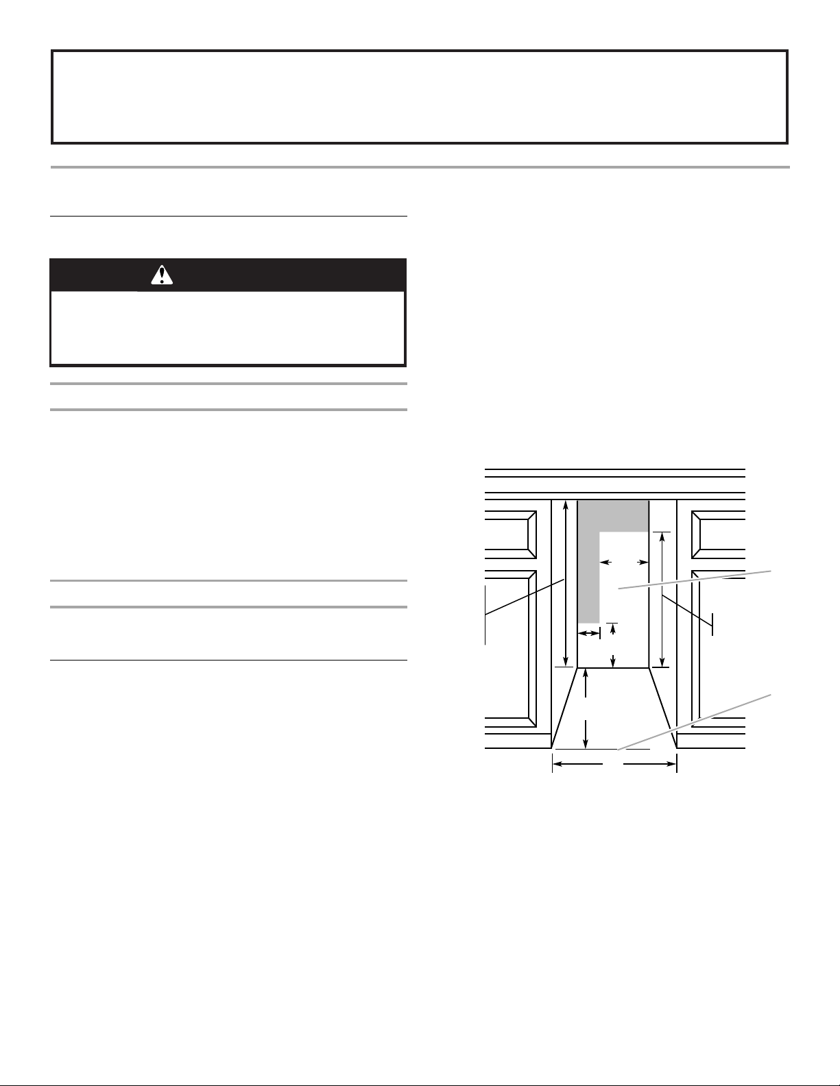
5. Bend the copper tubing to meet the water line inlet which is
located on the back of the ice maker cabinet as shown. Leave
a coil of copper tubing to allow the ice maker to be pulled out
of the cabinet or away from the wall for service.
Rear View
A. Line to ice maker
B. Nut (purchased)
C. Ferrule (purchased)
D. Supplied line from ice maker
8. Install the water supply tube clamp around the water supply
line to reduce strain on the coupling.
9. Turn shutoff valve ON.
10. Check for leaks. Tighten any connections (including
connections at the valve) or nuts that leak.
Drain Pump Installation
(on some models)
NOTES:
■ Connect drain pump to your drain in accordance with all state
and local codes and ordinances.
■ It may be desirable to insulate drain tube thoroughly up to
drain inlet to minimize condensation on the drain tube.
Insulated tube kit Part Number W10365792 is available for
purchase.
■ Drain pump is designed to pump water to a maximum height
of 10 ft (3 m). Use only Whirlpool approved drain pump kit Part
Number 1901A.
■ Do not connect the outlet end of the drain tube to a closed
pipe system to keep drain water from backing up into the ice
maker.
Kit Contains:
■ Drain pump kit Part Number 1901A
■ ⁵⁄₈" I.D. x 5¹⁄₈" drain tube (ice maker bin to drain pump reservoir
inlet)
■ ¹⁄₂" I.D. x 10 ft (3 m) drain tube hose (drain pump discharge to
household drain)
■ ⁵⁄₁₆" I.D. x 32" (81 cm) vent tube (drain pump reservoir vent to
ice maker cabinet back)
■ Cable clamps (secures vent tube to back of ice maker) (3)
■ #8-32 x ³⁄₈" pump mounting screws (secures drain pump to
baseplate and clamps to back of ice maker) (5)
■ ⁵⁄₈" small adjustable hose clamp (secures vent to drain pump)
■ ⁷⁄₈" large adjustable hose clamp, (secures drain tube to ice
maker bin and drain pump reservoir inlet) (3)
■ Rear panel (2)
■ Instruction sheet
A. Copper tubing
B. Water supply tube clamp
4
C. Inlet water tube clamp and
supply line connector
If Ice Maker Is Currently Installed
WARNING
Electrical Shock Hazard
Disconnect power before servicing.
Replace all parts and panels before operating.
Failure to do so can result in death or electrical shock.
A
B
C
D
E
A
C
B
A
A
A
B
C
D
Drain Pump Installation
NOTE: If ice maker is not installed, please proceed to “Drain
Pump Installation” section.
1. Push the selector switch to the Off position.
2. Unplug ice maker or disconnect power.
3. Turn off water supply. Wait 5 to 10 minutes for the ice to fall
into the storage bin. Remove all ice from bin.
4. Unscrew the drain cap from the bottom of the water pan
located inside the storage bin. Allow water to drain
completely. Replace drain cap. See “Drain Cap” illustration.
Drain Cap
NOTE: Do not kink, smash or damage tubes or wires during
installation.
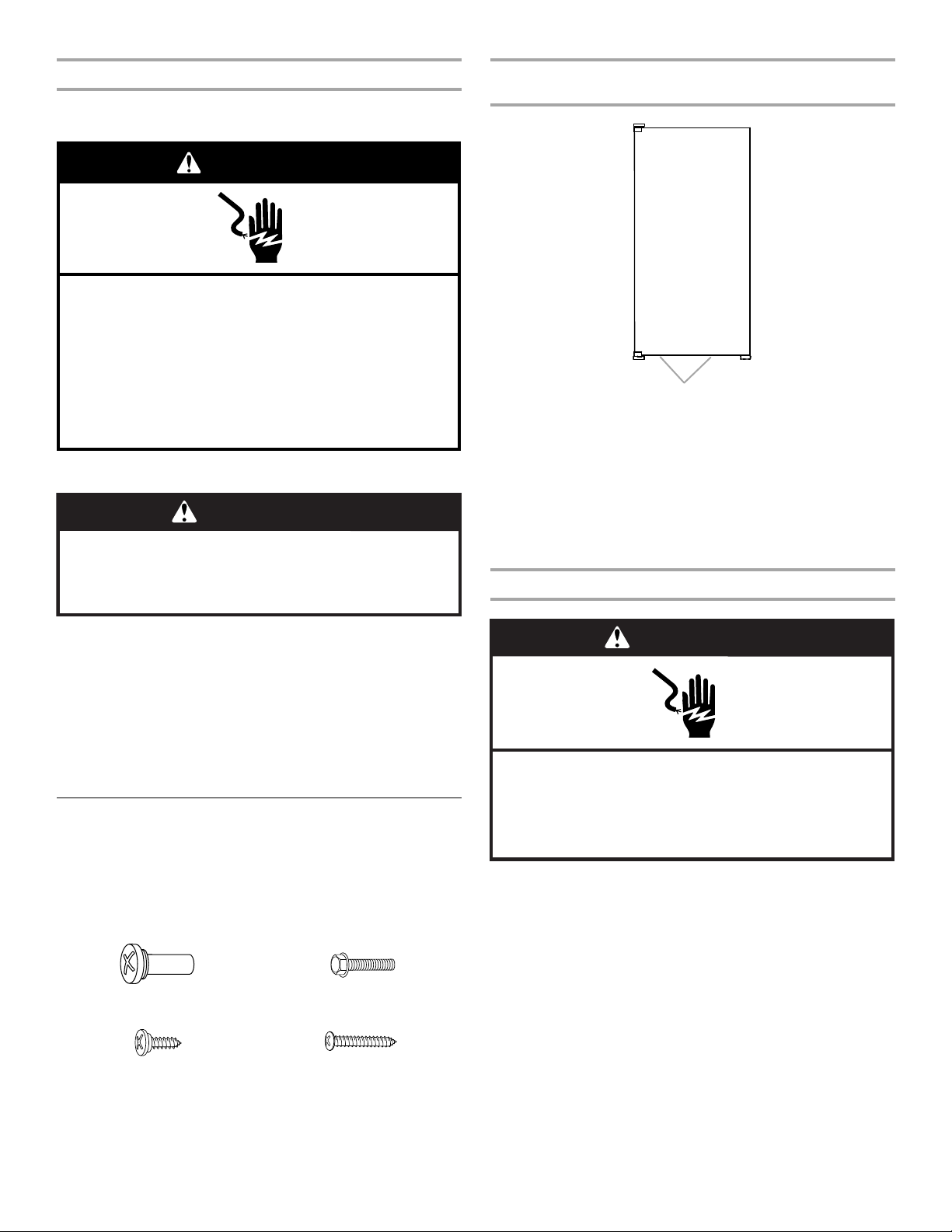
1. Unplug ice maker or disconnect power.
2. Remove rear panel. See “Rear Panel” illustration for 5 screw
locations. Pull rear panel away from the drain tube and
discard.
Rear Panel
A. Screw locations
3. Remove the old drain tube and clamp attached to the ice
maker bin.
NOTE: Discard old drain tube and clamp.
4. Install new drain tube (⁵⁄₈" I.D. x 5¹⁄₈") from ice maker bin to
drain pump reservoir inlet using new adjustable clamps. See
“Drain Tube” illustration.
NOTES:
■ Do not kink.
■ Trim tube length, if required.
Drain Tube
A. Drain cap
5. If ice maker is built into cabinets, pull ice maker out of the
opening.
6. Disconnect water supply line. See “Water Supply Line”
illustration.
Water Supply Line
¹⁄₄
" copper tubing
A.
B. Cable clamp
C.
¹⁄₄
" compression nut
D. Ferrule (sleeve)
E. Ice maker connection
A.
⁷⁄₈
" adjustable hose clamp
B. Drain tube (ice bin to drain pump)
C.
⁷⁄₈
" adjustable hose clamp
D. Drain pump reservoir inlet
5. Install vent tube (⁵⁄₁₆" I.D. x 32" [81 cm]) to drain pump
reservoir vent. Use one ⁵⁄₈" small adjustable clamp, supplied.
See “Parts Locations” illustration.
NOTE: Do not install household drain tube at this time.
5
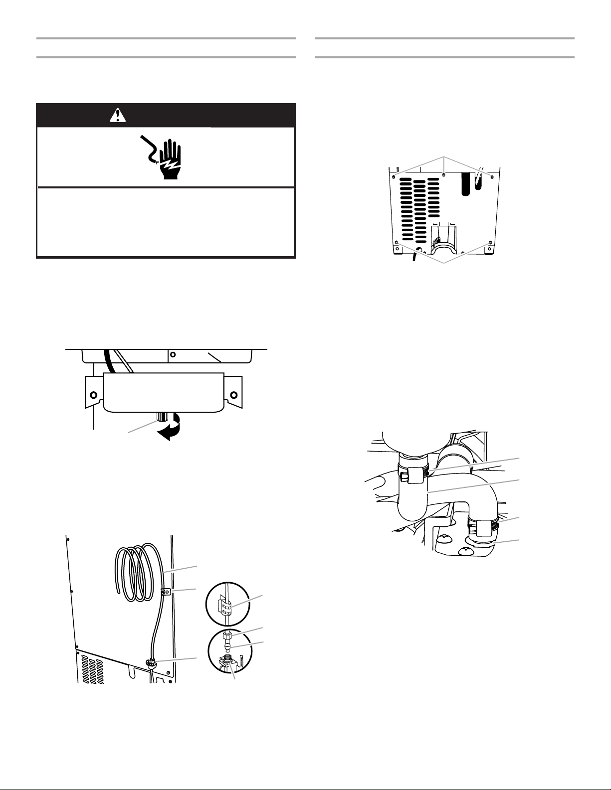
Parts Locations
A
B
C
D
E
FG
A
A
A
B
A. Vent tube
B.
⁵⁄₈
" hose clamp
C. Drain pump discharge tube
D. Drain pump
6. Remove power cord clamp and ground screw attached to ice
maker power cord, which is mounted to the unit base. See
“Parts Locations” illustration.
NOTE: Clamp and screw will be reused.
7. Slide drain pump into the ice maker base on the right side.
The pump mounting tab should slip into the rectangular slot in
the ice maker base. It will be necessary to tip the pump
slightly to slip into the slot. See “Drain Pump Mounting Tab
Slot” illustration.
E. Ice maker unit power cord
F. #8-32 x
G. Drain pump power cord, clamp
³⁄₈
mounting screws
and screw
" pump
Drain Pump Mounting Tab Slot
Drain Pump Installed
A. Drain pump installed
8. Align the 2 screw holes at the rear of the pump. Use two #8-32
x ³⁄₈" screws, supplied. See “Parts Locations” illustration.
9. Connect drain tube to ice maker bin outlet (⁵⁄₈" I.D.), using ⁷⁄₈"
adjustable clamp, supplied. See “Drain Tube” illustration.
10. Coil ice maker power cord into a 4" (10.2 cm) diameter coil.
Wrap electrical tape around the power cord in several places
to keep the cord in a coil. Locate coiled power cord between
the drain pump and side of enclosure and plug into the
receptacle of the drain pump. See “Parts Locations”
illustration.
11. Attach the drain pump power cord to ice maker unit base with
clamp and screw (removed in Step 6) that was used to attach
ice maker power cord. See “Parts Locations” illustration.
12. Place new rear panel (small one for 15" ice makers, large one
for 18") against the back of the ice maker. Route the vent tube
and drain pump discharge tube through cutouts in the rear
panel.
13. Secure rear panel with original screws. See “Rear Panel”
illustration.
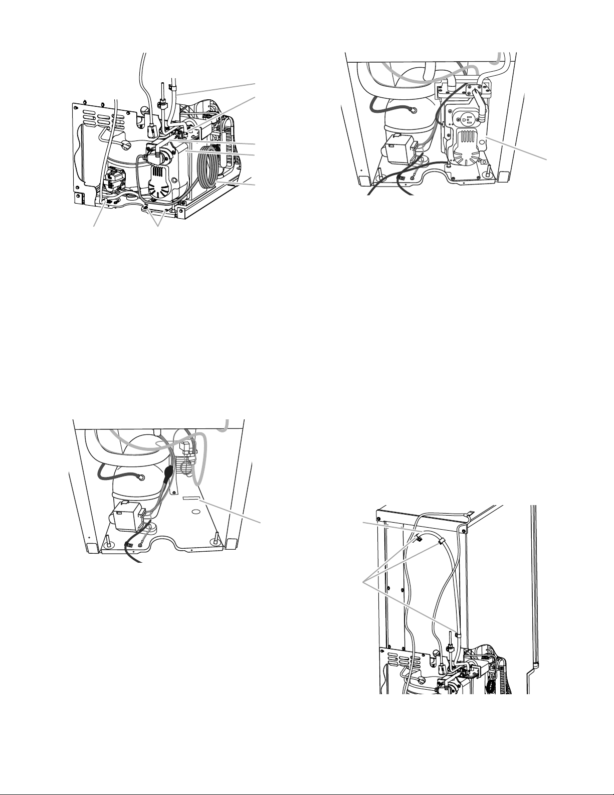
14. Secure vent tube to back of ice maker using three clamps and
three #8-32 x ³⁄₈" screws, supplied. See “Vent Tube”
illustration.
Vent Tube
NOTE: Do not pinch, kink or damage the vent tube. Check that it
is not damaged, or pinched or kinked between the cabinet and
the ice maker.
A. Mounting tab slot
A. Vent tube
B. Clamps and screws
6
15. Attach ¹⁄₂" I.D. x 10 ft (3 m) drain tube to pump discharge tube.
Electrical Shock Hazard
Plug into a grounded 3 prong outlet.
Do not remove ground prong.
Do not use an adapter.
Do not use an extension cord.
Failure to follow these instructions can result in death,
fire, or electrical shock.
WARNING
1⁷⁄₈"
(4.8 cm)
23"
(58.4 cm)
2" - 1¹⁄₂"
(5 cm - 3.8 cm)
1" (2.54 cm)
A
D
C
B
See “Parts Locations” illustration.
NOTE: Do not connect outlet end of drain tube to a closed
pipe system to keep drain water from backing up into the ice
maker.
16. Connect ice maker to water supply and install ice maker as
specified by the product installation instructions.
17. Check all connections for leaks.
IMPORTANT: A drain pump is necessary when a floor drain is not
available. A Drain Pump kit, Part Number 1901A, is available for
purchase.
Side View
18. Plug in ice maker or reconnect power.
19. Turn on ice maker.
20. Wait for rinsing cycle, approximately 5 minutes, to be sure the
ice maker is operating properly.
Drain Connection
Gravity Drain System
Connect the ice maker drain to your drain in accordance with all
state and local codes and ordinances. If the ice maker is provided
with a gravity drain system, follow these guidelines when installing
drain lines. This will help keep water from flowing back into the ice
maker storage bin and potentially flowing onto the floor, causing
water damage.
■ Drain lines must have a minimum of ⁵⁄₈" (15.88 mm) I.D. (inside
diameter).
■ Drain lines must have a 1" drop per 48" (2.54 cm drop per
122 cm) of run or ¹⁄₄" drop per 12" (6.35 mm per 30.48 cm) of
run and must not have low points where water can settle.
■ The floor drains must be large enough to accommodate
drainage from all drains.
■ The ideal installation has a standpipe with a 1¹⁄₂" (3.81 cm) to
2" (5.08 cm) PVC drain reducer installed directly below the
outlet of the drain tube as shown. You must maintain a
1" (2.54 cm) air gap between the drain hose and the
standpipe.
■ Do not connect the outlet end of the drain tube to a closed
pipe system to keep drain water from backing up into the ice
maker.
A. Drain hose
B. 1" (2.54 cm) air gap
C. PVC drain reducer
D. Center of drain should be 23" (58.4 cm) from
front of door, with or without the
panel on the door. The drain should also be
centered from left to right (7
from either side of the ice maker).
³⁄₄
" (1.91 cm)
⁵⁄₁₆
" [18.56 cm]
Drain Pump System (on some models)
IMPORTANT:
■ Connect the ice maker drain to your drain in accordance with
the International Plumbing Code and any local codes and
ordinances.
■ The drain pump discharge line must terminate at an open
sited drain.
■ Maximum rise 10 ft (3.1 m)
■ Maximum run 100 ft (30.5 m)
NOTES:
■ If the drain hose becomes twisted and water cannot drain,
your ice maker will not work.
■ It may be desirable to insulate the drain line thoroughly up to
the drain inlet. An Insulation Sleeve kit, Part Number
W10365792, is available for purchase.
■ Do not connect the outlet end of the drain tube to a closed
pipe system to keep drain water from backing up into the ice
maker.
7
Connecting the Drain
Electrical Shock Hazard
Plug into a grounded 3 prong outlet.
Do not remove ground prong.
Do not use an adapter.
Do not use an extension cord.
Failure to follow these instructions can result in death,
fire, or electrical shock.
WARNING
WARNING
Excessive Weight Hazard
Use two or more people to move and install ice maker.
Failure to do so can result in back or other injury.
A
WARNING
Electrical Shock Hazard
Disconnect power before servicing.
Replace all parts and panels before operating.
Failure to do so can result in death or electrical shock.
After ensuring that the drain system is adequate, follow these
steps to properly place the ice maker:
1. Plug into a grounded 3 prong outlet.
Remove Stainless Steel Door Wrap Panel
(on some models)
A. Hex-head screws
1. Remove the two hex-head screws located under the stainless
steel door wrap panel flange on the bottom of the door.
2. Pull up and outward on the door wrap panel from the bottom.
3. Rotate the door wrap panel until it separates from the door
and pull up.
NOTE: Be sure the edge guards do not separate from the
door wrap panel.
2. Style 1—For gravity drain system, push the ice maker into
position so that the ice maker drain tube is positioned over the
PVC drain reducer. See “Gravity Drain System.”
Style 2—For drain pump system connect the drain pump
outlet hose to the drain. See “Drain Pump System.”
3. Recheck the ice maker to be sure that it is level. See
“Leveling.”
4. If it is required by your local sanitation code, seal the cabinet
to the floor with an approved caulking compound after all
water and electrical connections have been made.
Door Reversal—Side Swing Only
Tools Needed
Gather the required tools and parts before starting installation.
■ ⁵⁄₁₆" wrench ■ Flat putty knife
■ ¹⁄₄" wrench ■ Phillips screwdriver
Hinge pin
⁵⁄₁₆
" hex-head hinge screw
Door Stop and End-Cap Reversal
1. Unplug the ice maker or disconnect power.
2. Remove the handle screws and handle (on some models).
3. Remove the hinge pin from the top hinge.
4. Remove the door from the hinges and replace the top hinge
pin.
5. Remove the screw and door stop at corner A. Remove the
screw and end cap at corner C. Place the door stop at corner
C, and tighten screw. Place the end cap at corner A, and
tighten screw.
Handle screw End cap screw
8
 Loading...