

KitchenAid KUDW02FRBL0, KUDW02FRSS0, KUDU02VRPA0, KUDU02VRSS0, KUDU02VRMT0 Installation Guide
...
t
KitchenA_d °
HOME APPLIANCES
Table of Contents ............................................................................. 2
Table des mati_res ......................................................................... 19
8572290
_r
8572290
TabUe of Contents
Dishwasher Safety ................................. 2
installation Requirements ........................... 3
Tools and parts ................................. 3
Location Requirements .......................... 3
Drain Requirements ............................. 5
Water Supply Requirements ...................... 5
Electrical Requirements .......................... 5
Installation instructions ............................. 6
Prepare cabinet opening
using existing utility hookups ..................... 6
Prepare cabinet opening
where there are no existing utility hookups .......... 7
Prepare dishwasher ............................. 9
Make electrical connection ...................... 13
Connect to water supply ........................ 14
Connect to drain ............................... 15
Secure dishwasher in cabinet opening ............. 15
Dishwasher Safety
Your safety and the safety of others are very important.
We have provided many important safety messages in this manual and on your appliance. Always read and obey all safety
messages.
This is the safety alert symbol.
This symbol alerts you to potential hazards that can kill or hurt you and others.
All safety messages will follow the safety alert symbol and either the word "DANGER" or "WARNING."
These words mean:
You can be killed or seriously injured if you don't immediately
follow instructions.
You can be killed or seriously injured if you don't follow
instructions.
All safety messages will tell you what the potential hazard is, tell you how to reduce the chance of injury, and tell you what can
happen if the instructions are not followed.
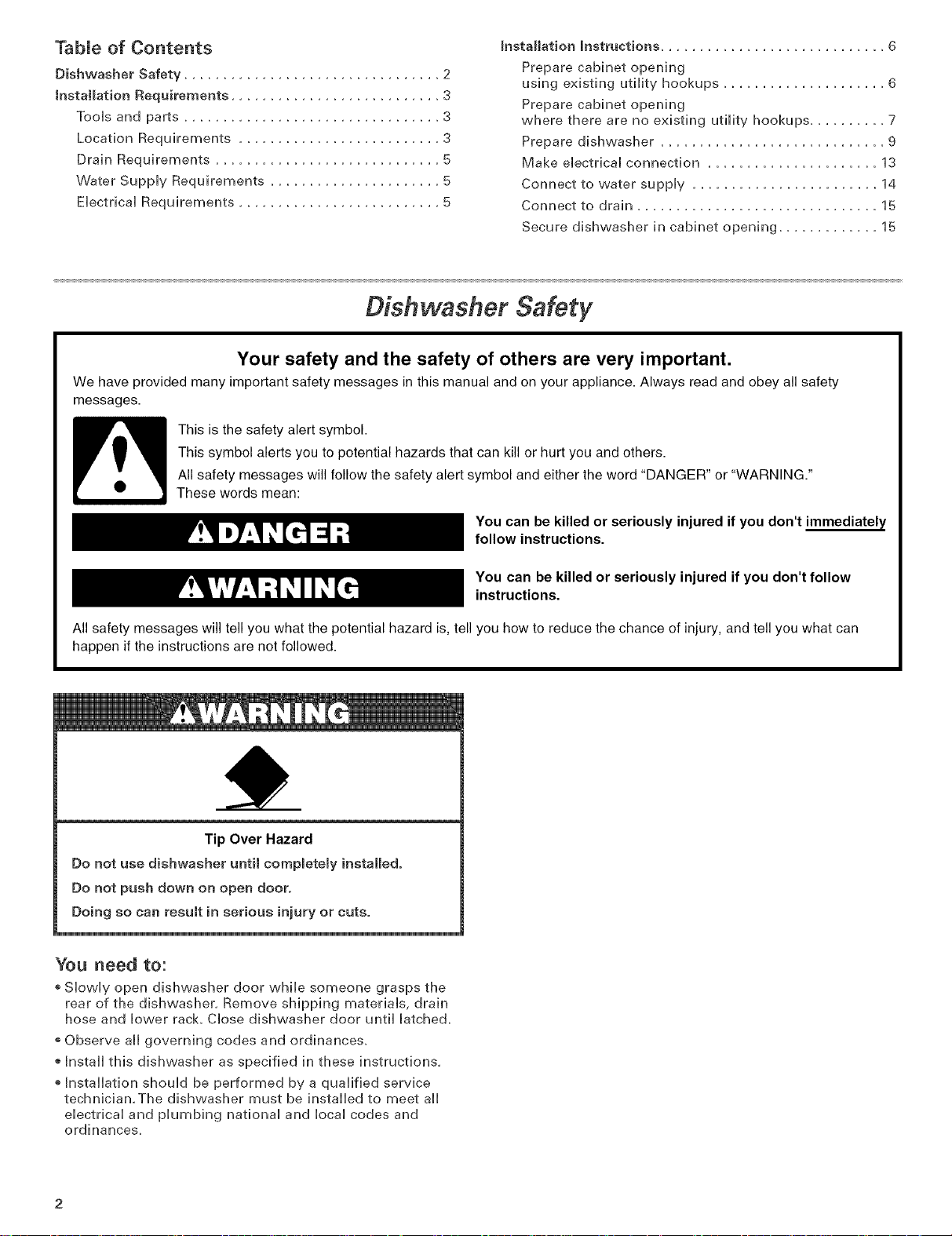
Tip Over Hazard
Do not use dishwasher until compmetemy installed.
Do not push down on open door.
Doing so can result in serious injury or cuts.
You need to:
o Slowly open dishwasher door while someone grasps the
rear of the dishwasher, Remove shipping materials, drain
hose and lower rack Close dishwasher door until latched.
Observe all governing codes and ordinances.
Install this dishwasher as specified in these instructions,
Installation should be performed by a qualified service
technician,The dishwasher must be installed to meet all
electrical and plumbing national and local codes and
ordinances.
Installation Requirements
Location Requirements
TooJs and Parts
Gather the required toois and parts before starting
installation. Read and follow the instructions provided with
any toois Hsted here.
AH installations
Tools needed:
+ pliers
+ PhHHps screwdriver
+ 5/16" and 1/4" nut drivers
or hex sockets
+ measuring tape or ruler
+ 10" adjustable wrench that
opens to 1-1/8" {2.9 cm)
+ fiat+Made screwdriver
®utility knife
+ 2 twist+on wire connectors
which are the proper size
to connect your household
wiring to 16+gauge wiring
in dishwasher
+ small level
+TORX+T15 screwdriver (if
installing custom front
panels)
In addition, for new installations
Tools needed: Parts needed:
+ electric drill with 1/2", 3/4"
and 1-1/2" hole saw bits
+ small tubing cutter
®wire stripper
®1-1/2"+2" screw-type clamp
if connecting to waste+tee
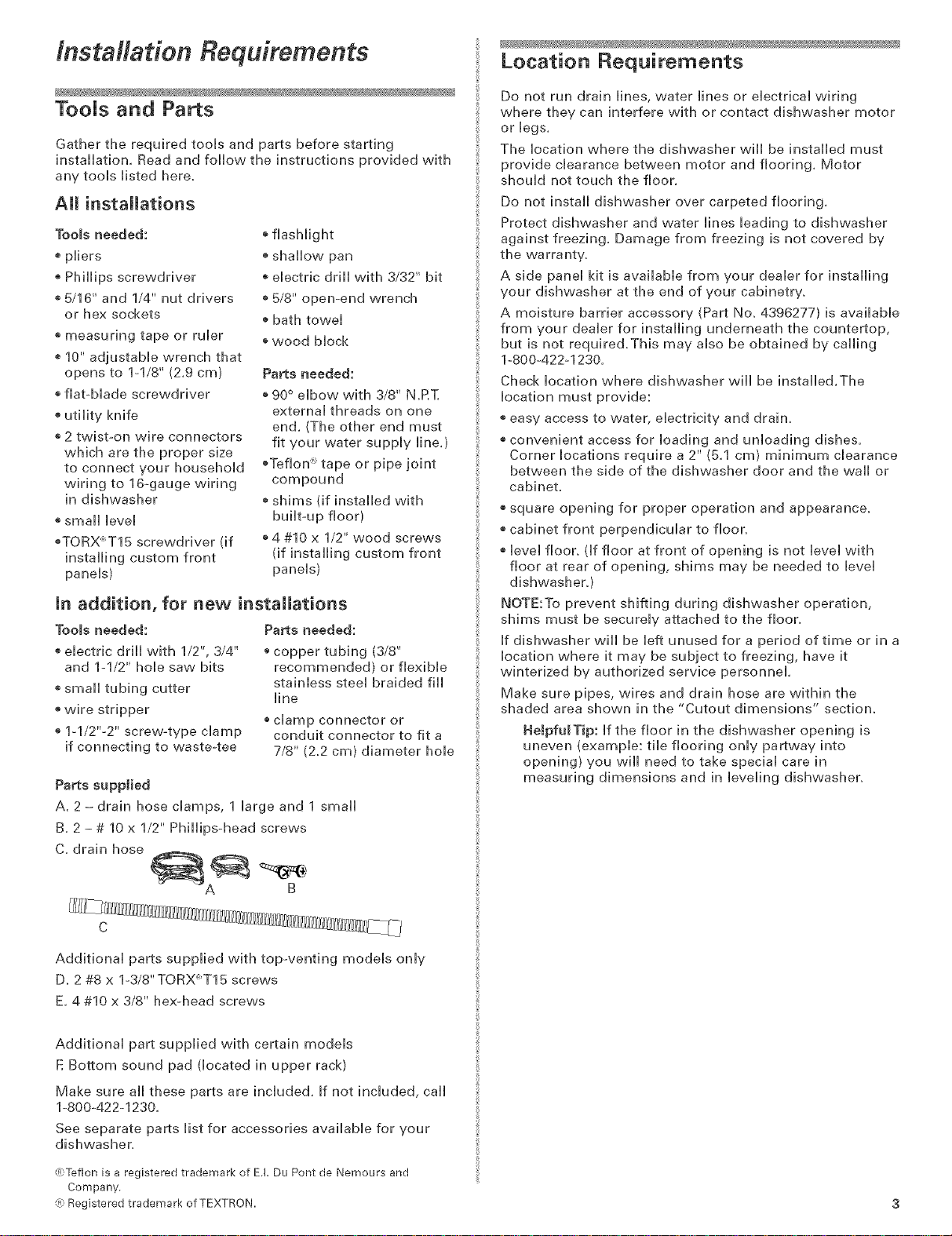
Parts supplied
A. 2 - drain hose clamps, 1 large and 1 small
B. 2 - # 10 x 1/2" Phillips-head screws
C. drain hose
®flashlight
+ shallow pan
+ electric drill with 3/32" bit
+ 5/8" open-end wrench
+ bath towel
+ wood block
Parts needed:
+90° elbow with 3/8" N,RT,
external threads on one
end, (The other end must
fit your water supply line,)
+Teflon x tape or pipe joint
compound
+shims (if installed with
built+up floor)
+4 #10 x 1/2" wood screws
(if installing custom front
panels)
+ copper tubing (3/8"
recommended) or flexible
stainless steel braided fill
line
+ clamp connector or
conduit connector to fit a
7/8" (2.2 cm) diameter hole
Do not run drain lines, water lines or electrical wiring
where they can interfere with or contact dishwasher motor
or legs.
The location where the dishwasher will be installed must
provide clearance between motor and flooring. Motor
should not touch the floor.
Do not install dishwasher over carpeted flooring.
Protect dishwasher and water lines leading to dishwasher
against freezing. Damage from freezing is not covered by
the warrant%
A side panel kit is available from your dealer for installing
your dishwasher at the end of your cabinetry.
A moisture barrier accessory (Part No. 4396277) is available
from your dealer for installing underneath the countertop,
but is not required.This may also be obtained by calling
1-800-422+1230.
Check location where dishwasher will be installed.The
location must provide:
+ easy access to water, electricity and drain.
+ convenient access for loading and unloading dishes.
Corner locations require a 2" (5.1 cm) minimum clearance
between the side of the dishwasher door and the wail or
cabinet.
+ square opening for proper operation and appearance.
+ cabinet front perpendicular to floor.
+ level floor. (if floor at front of opening is not level with
floor at rear of opening, shims may be needed to level
dishwashery
NOTE:To prevent shifting during dishwasher operation,
shims must be securely attached to the floor.
If dishwasher will be left unused for a period of time or in a
location where it may be subject to freezing, have it
winterized by authorized service personnel.
Make sure pipes, wires and drain hose are within the
shaded area shown in the "Cutout dimensions" section.
HelpfulTip: if the floor in the dishwasher opening is
uneven (example: tile flooring only partway into
opening) you will need to take special care in
measuring dimensions and in leveling dishwasher.
B
C
Additional parts supplied with top-venting models only
D. 2 #8 x l+3/8"TORX+T15 screws
E, 4 #10 x 3/8" hex+head screws
Additional part supplied with certain models
E Bottom sound pad (located in upper rack)
Make sure ail these parts are included. If not included, cail
1-800+422-1230.
See separate parts list for accessories available for your
dishwasher.
@Teflon is a registered trademark of E.I. Du Pont de Nemours and
Company.
{R_Registered trademark of TEXTRON.
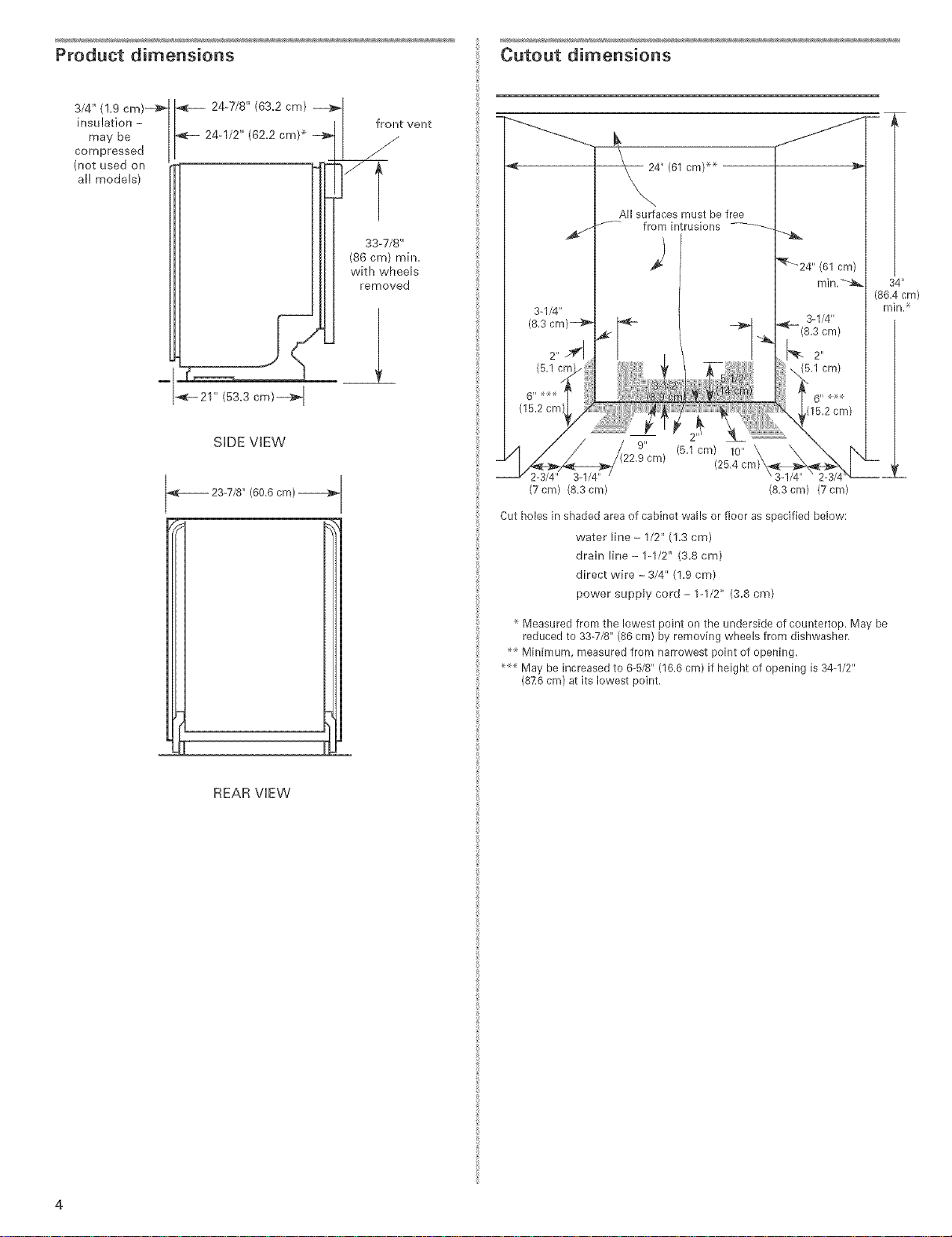
Product dimensions
Cutout dimensions
3/4" (!.9 cm)-a_
insu !ation -
may be
compressed
(not used on
al! models)
24-7/8" (63.2 cm) _1
24-1/2" (62.2 cm) _ _11 _
_- 21" (53.3 cm)--_ I
SIDE VIEW
23-7/8" (60.6 cm)
/
I I front vent
I Ill SS-TJS"
Ill I (s6cm>mh_.
removed
All surfaces must be free
/'_- from intrusions
I ÷1
._ (5.1 cm) 10"
2-3/4" 3-1/4"
(7 cm) (8.3 cm) (8.3 cm) (7 cm)
Cut holes in shaded area of cabinet walls or floor as specified below:
water line - 1/2" (!.3 cm)
drain line- 1-1/2" (3.8 cm)
direct wire - 3/4" (!.9 cm)
power supply cord - 1-1/2" (3.8 cm)
(25.4
34 _'
(86.4 cm)
min.
!
REAR VIEW
Measured from the lowest point on the underside of countertop. May be
reduced to 33-7/8" (86 cm) by removing wheels from dishwasher.
Minimum, measured from narrowest point of opening.
May be increased to 6-5/8" (16.6 cm) if height of opening is 34-1/2"
(876 cm) at its lowest point.

Drain Requirements
EJectricaJ Requirements
o Use the new drain hose suppHbd with your dishwasher.
IftMs is not [ong enough, use a new drain hose with a
maximum [ength of 12 feet (3.7 m) that meets all[
current AHAM/[APMO test standards, is resistant to
heat and detergent, and fits the 1" (2.5 cm) drain
connector of the dishwasher.
o Connect drain hose to waste tee or disposer inlet
above drain trap in house plumbing and 20" (50.8 cm)
minimum above the floor, it is recommended that the
drain hose either be looped up and securely fastened
to the underside of the counter, or be connected to an
air gap.
air gap
o Use an air gap if the drain hose is connected to house
plumbing lower than 20" (50.8 cm} above subfloor or
floor.
o Use 1/2" minimum I.D. drain line fittings.
Water SuppJy Requirements
_A hot water line with 20-120 psi (138-862 kPa) water
pressure.
o 120°F (49°C) water at dishwasher.
o 3/8" O.D. copper tubing with compression fitting or
flexible stainless steel braided fill line (1/2" minimum
plastic tubing is not recommended).
o A 90 ° elbow with 3/8" N.RT. external pipe threads on
one end.
Do not solder within 6" (15.2 cm) from water inlet valve.
Contact a qualified electrician.
Assure that the electrical installation is adequate and in
conformance with aii national and local codes and
ordinances.
You must have:
o 120-volt, 60 Hz, AC-only, 15 or 20 amp, fused electrical
suppl%
®Copper wire only.
We recommend:
o A timeodelay fuse or circuit breaker.
o A separate circuit,
ff direct wiring dishwasher:
Use flexible, armored or nonometallic sheathed, copper
wire with grounding wire that meets the wiring
requirements for your home and local codes and
ordinances.
Use strain relief method provided with house wiring
junction box or install a U.L.-listed/CSAocertified clamp
connector to the house wiring junction box. if using
conduit, use a U.L.-listed/CSA-certified conduit connector.
_fconnecting dishwasher with a power supply cord:
Use Power Supply Cord Kit (Part No. 4317824} marked for
use with dishwashers. Kit contents include:
-Volex, inc., UL listed 16 gauge 3 wire power supply
cord with 3 prong grounded plug.
- Neer C-500 7/8 inch strain relief.
- 3 wire connectors.
- Part No. 302797 grommet
Follow the kit instructions for installing the power
supply cord.
o Power supply cord must plug into a mating three prong,
grounded outlet, located in the cabinet next to the
dishwasher opening. Outlet must meet all local codes and
ordinances.
Installation Instructions
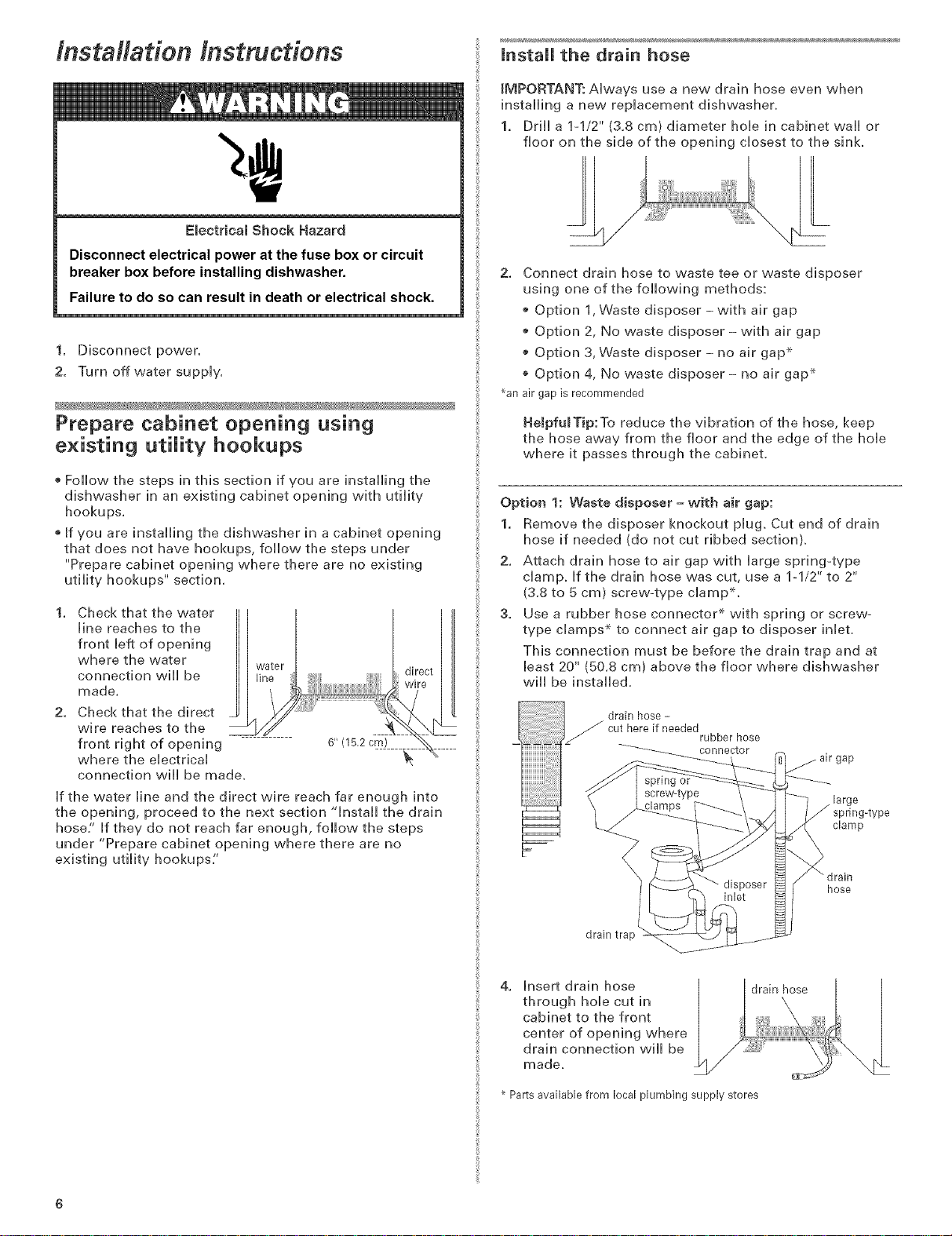
EBectrical Shock Hazard
Disconnect electrical power at the fuse box or circuit
breaker box before installing dishwasher.
Failure to do so can result in death or electrical shock.
1. Disconnect power.
2. Turn off water suppiy.
JnstalJ the drain hose
IMPORTANT: Always use a new drain hose even when
installing a new replacement dishwasher,
1. Drill a 1-1/2" (3,8 cm) diameter hob in cabinet wall or
floor on the side of the opening closest to the sink
2. Connect drain hose to waste tee or waste disposer
using one of the following methods:
o Option 1, Waste disposer- with air gap
o Option 2, No waste disposer- with air gap
o Option 3, Waste disposer- no air gap _
Option 4, No waste disposer - no air gap _
_anair gapis recommended
Prepare cabinet opening using
existing utility hookups
Follow the steps in this section if you are installing the
dishwasher in an existing cabinet opening with utility
hookups.
®Jf you are installing the dishwasher in a cabinet opening
that does not have hookups, follow the steps under
"Prepare cabinet opening where there are no existing
utility hookups" section.
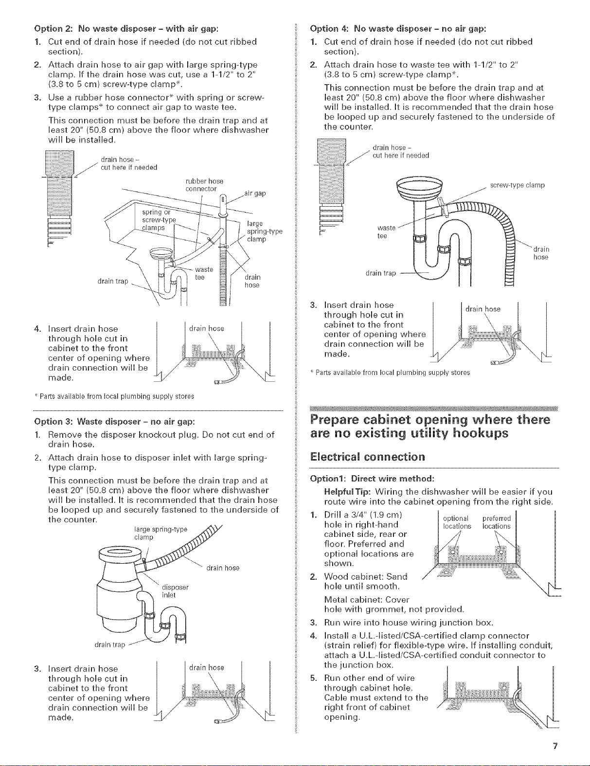
1. Check that the water
line reaches to the
front left of opening
where the water
connection will be
made.
2. Check that the direct _
wire reaches to the
front right of opening 6" (15.2 cm)
where the electrical
connection will be made.
If the water line and the direct wire reach far enough into
the opening, proceed to the next section "install the drain
hose/' Jf they do not reach far enough, follow the steps
under "Prepare cabinet opening where there are no
existing utility hookups:'
HeJpfuITip:To reduce the vibration of the hose, keep
the hose away from the floor and the edge of the hole
where it passes through the cabinet.
Option 1: Waste disposer -with air gap:
1. Remove the disposer knockout plug. Cut end of drain
hose if needed (do not cut ribbed section).
2. Attach drain hose to air gap with large spring-type
clamp, if the drain hose was cut, use a 1-1/2" to 2"
(3.8 to 5 cm) screw-type clampX.
3. Use a rubber hose connector _ with spring or screw-
type clamps _ to connect air gap to disposer inlet.
This connection must be before the drain trap and at
bast 20" (50.8 cm) above the floor where dishwasher
will be installed,
drain hose -
cut here if needed
rubber hose
ector
gap
large
J spring-type
clamp
_ drain
hose
drain trap
4. Insert drain hose
through hole cut in
cabinet to the front
center of opening where
drain connection will be
made,
Parts available from local plumbing supply stores
drain hose
Option 2: No waste disposer - with air gap:
1. Cut end of drain hose if needed (do not cut ribbed
section).
2. Attach drain hose to air gap with large spring-type
damp. if the drain hose was cut, use a 1-1/2" to 2"
(&8 to 5 cm) screw-type damp ×,
3. Use a rubber hose connector _ with spring or screw-
type damps .×.to connect air gap to waste tee_
This connection must be before the drain trap and at
least 20" (50.8 cm) above the floor where dishwasher
will be installed_
drain hose-
cut here if needed
rubber hose
connector
large
spring4ype
waste
drain trap hose
tee drain
Option 4: No waste disposer - no air gap:
1. Cut end of drain hose if needed (do not cut ribbed
section),
2. Attach drain hose to waste tee with lq/2" to 2"
(3,8 to 5 cm) screw-type clampX,
This connection must be before the drain trap and at
bast 20" (50,8 cm) above the floor where dishwasher
will be installed, it is recommended that the drain hose
be looped up and securely fastened to the underside of
the counter,
4. insert drain hose |
through hob cut in
cabinet to the front
center of opening where
drain connection will be /
made.
Parts available from local plumbing supply stores
drain hose
Option 3: Waste disposer - no air gap:
1. Remove the disposer knockout plug. Do not cut end of
drain hose.
2. Attach drain hose to disposer inlet with large spring_
type damp.
This connection must be before the drain trap and at
least 20" (50.8 cm) above the floor where dishwasher
will be installed, it is recommended that the drain hose
be looped up and securely fastened to the underside of
the counter.
large spring-type
clamp
drain hose
disposer
inlet
drain trap
3. insert drain hose |
through hole cut in
cabinet to the front
center of opening where
drain connection will be
made.
drain hose
3. Insert drain hose
through hole cut in
cabinet to the front
center of opening where
drain connection will be
made.
Parts available from local plumbing supply stores
drain hose
Prepare cabinet opening where there
are no existing utility hookups
Electrical connection
Option1: Direct wire method:
HeJpfu_Tip: Wiring the dishwasher wiii be easier if you
route wire into the cabinet opening from theri htside,
1. Drill a 3/4" (1,9 cm)
hob in rightohand
cabinet side, rear or
floor. Preferred and
optional locations are
shown,
2. Wood cabinet: Sand
hob until smooth.
Metal cabinet: Cover
hob with grommet, not provided.
3,
Run wire into house wiring junction box.
4.
Install a U.L.qisted/CSAocertified clamp connector
(strain relief) for flexibleotype wire. If installing conduit,
attach a U.L.-listed/CSA-certified conduit connector to
the junction box.
5,
Run other end of wire
through cabinet hole.
Cable must extend to the
right front of cabinet
opening.
_1_oOptional preferred
ns Iocat_i.,
Option2: Powersupplycordmethod:
NOTE:Amating,threeprong,ground-typewallreceptacle
isrequiredinacabinetnexttothedishwasheropening.
1. DrHHa1ol/2"
(3.8cm)hoHein optionalpreferred
thecabinetrear locationslocations
orside.Preferred[_!_i
andopfionaH ......
Hocafionsare
shown.
2. VVoodcabinet:
SandhoHeunfiH
smooth.
MetaH cabinet: Cover hoHe with grommet (Part No.
302797) incHuded with power suppHy cord kit.
mnstall the water line
HeJpfuJTip: Routing the water Hne through the Heft side
of cabinet opening will make water connection easier.
Drill a minimum 1/2" {1.3 cm) hole in the cabinet side,
rear or floor. Preferred and optional locations are
shown.
preferred
locations
2. Measure overall length
of copper tubing
required.
3. Attach copper tubing
to the water line with a
manual shutoff valve.
4. Slowly feed copper
tubing through hole in
cabinet. Copper tubing will bend and kink easily, so be
gentle.The copper tubing should be far enough into the
cabinet opening to connect it to dishwasher inlet on the
front left of the dishwasher.
5. Turn water shutoff valve to "ON" position. Flush water
into a shallow pan to get rid of particles that may clog
the inlet valve.
6. Turn shutoff valve to "OFF" position.
optional
locations
copper
tubing
mnstaH the drain hose
IMPORTANT: Always use a new drain hose.
1. Drill a 1-1/2" (3.8 cm)
diameter hole in
cabinet wall or floor on
the side of the opening
closest to the sink.
2. Connect drain hose to
waste tee or waste disposer using one of the following
methods:
o Option 1, Waste disposer-with air gap
o Option 2, No waste disposer- with air gap
o Option 3, Waste disposer - no air gap _
Option 4, No waste disposer - no air gap _
_anair gapis recommended
HeJpfulTip:To reduce the vibration of the hose, keep
the hose away from the floor and the edge of the hole
where it passes through the cabinet.
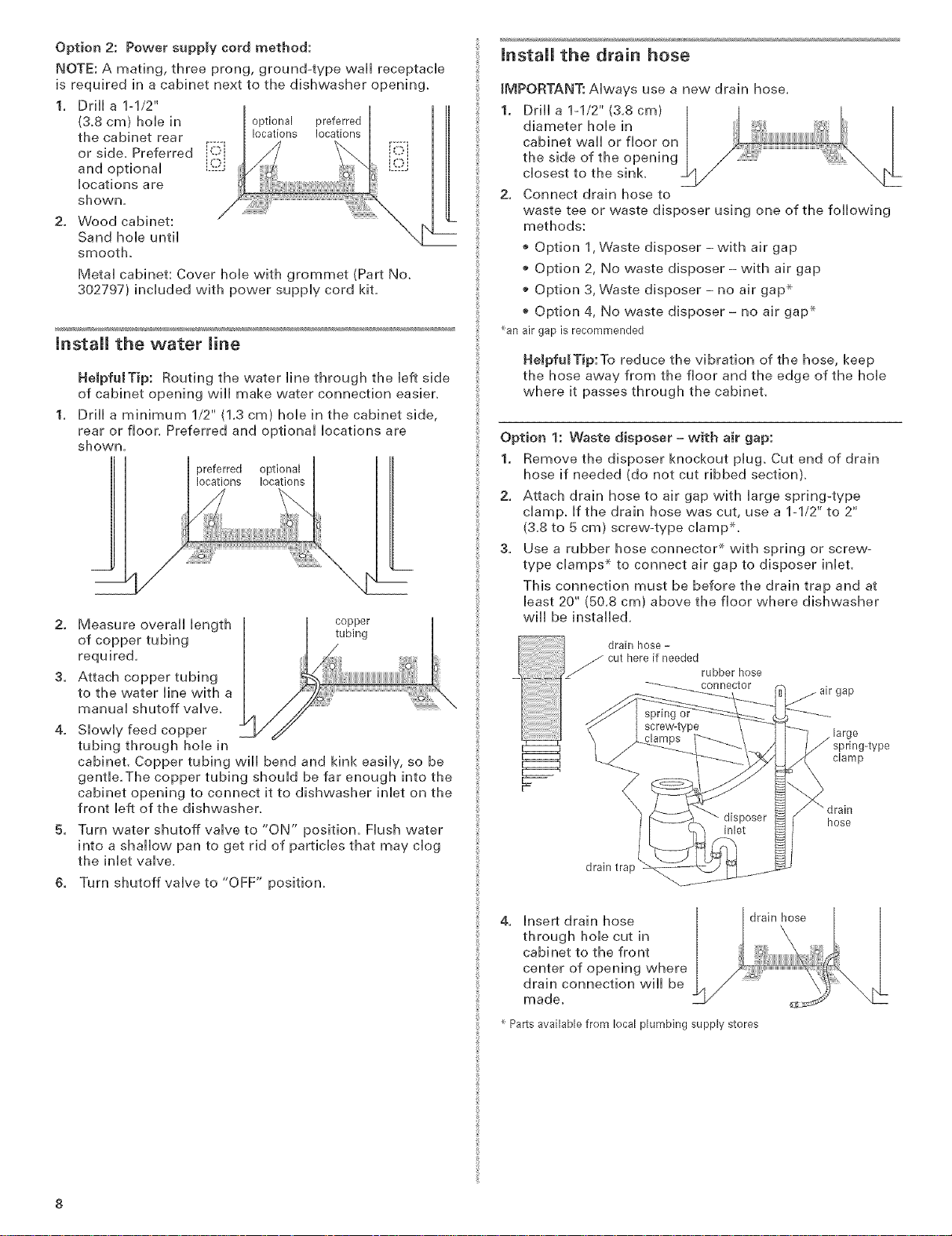
Option 1: Waste disposer = with air gap:
1. Remove the disposer knockout plug. Cut end of drain
hose if needed (do not cut ribbed section).
2. Attach drain hose to air gap with large spring-type
clamp. If the drain hose was cut, use a 1-1/2" to 2"
(3.8 to 5 cm) screw-type clamp*.
3. Use a rubber hose connector _ with spring or screw-
type clamps _ to connect air gap to disposer inlet.
This connection must be before the drain trap and at
least 20" (50.8 cm) above the floor where dishwasher
wi[[ be installed.
drain hose -
cut here if needed
rubber hose
connector
drain trap
gap
large
J spring-type
clamp
hose
4. Insert drain hose
through hole cut in
cabinet to the front
center of opening where
drain connection will be
made.
Parts available from local plumbing supply stores
drain hose
Option 2: No waste disposer = with air gap:
1. Cut end of drain hose if needed (do not cut ribbed
section).
2. Attach drain hose to air gap with Harge spring-type
champ. If the drain hose was cut, use a 1-1/2" to 2"
(&8 to 5 cm) screw-type cHamp x,
3. Use a rubber hose connector _ with spring or screw-
type champs .×.to connect air gap to waste tee_
This connection must be before the drain trap and at
Heast20" (50.8 cm) above the floor where dishwasher
wHHbe instaHHe&
cuthereif needed
rubber hose
connector
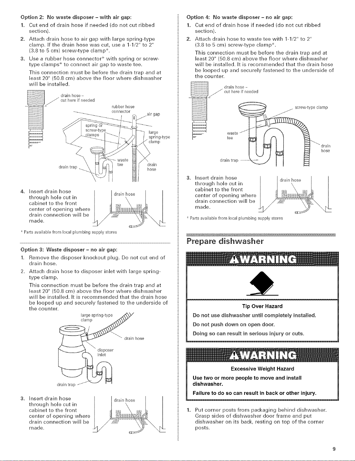
Option 4: No waste disposer = no air gap:
1. Cut end of drain hose if needed (do not cut ribbed
section),
2. Attach drain hose to waste tee with lq/2" to 2"
(3,8 to 5 cm) screw-type clampX,
This connection must be before the drain trap and at
least 20" (50,8 cm) above the floor where dishwasher
will be installed, it is recommended that the drain hose
be looped up and securely fastened to the underside of
the counter,
. drainhose-
drain trap hose
springor
large
spring4ype
waste
tee drain
4. hsert drain hose
through hoHecut in
cabinet to the front
center of opening where
drain connection wHHbe
L drain hose
made,
Parts available from local plumbing supply stores
Option 3: Waste disposer = no air gap:
1. Remove the disposer knockout pHug. Do not cut end of
drain hose.
2, Attach drain hose to disposer inlet with large spring_
type clamp,
This connection must be before the drain trap and at
least 20" (50,8 cm) above the floor where dishwasher
will be installed, It is recommended that the drain hose
be looped up and securely fastened to the underside of
the counter,
large spring-type
clamp
drain hose
3. Insert drain hose
through hole cut in
cabinet to the front
center of opening where
drain connection will be
made_
Parts available from local plumbing supply stores
_/_ drain hose
Prepare dishwasher
Tip Over Hazard
Do not use dishwasher until compietemy installed,
Do not push down on open door,
Doing so can result in serious injury or cuts.
drain trap
3. Insert drain hose
through hole cut in
cabinet to the front
center of opening where
drain connection will be
made,
disposer
inlet
drain hose
Excessive Weight Hazard
Use two or more people to move and install
dishwasher.
Failure to do so can result in back or other injury.
Put corner posts from packaging behind dishwasher,
Grasp sides of dishwasher door frame and put
dishwasher on its back, resting on top of the corner
posts,
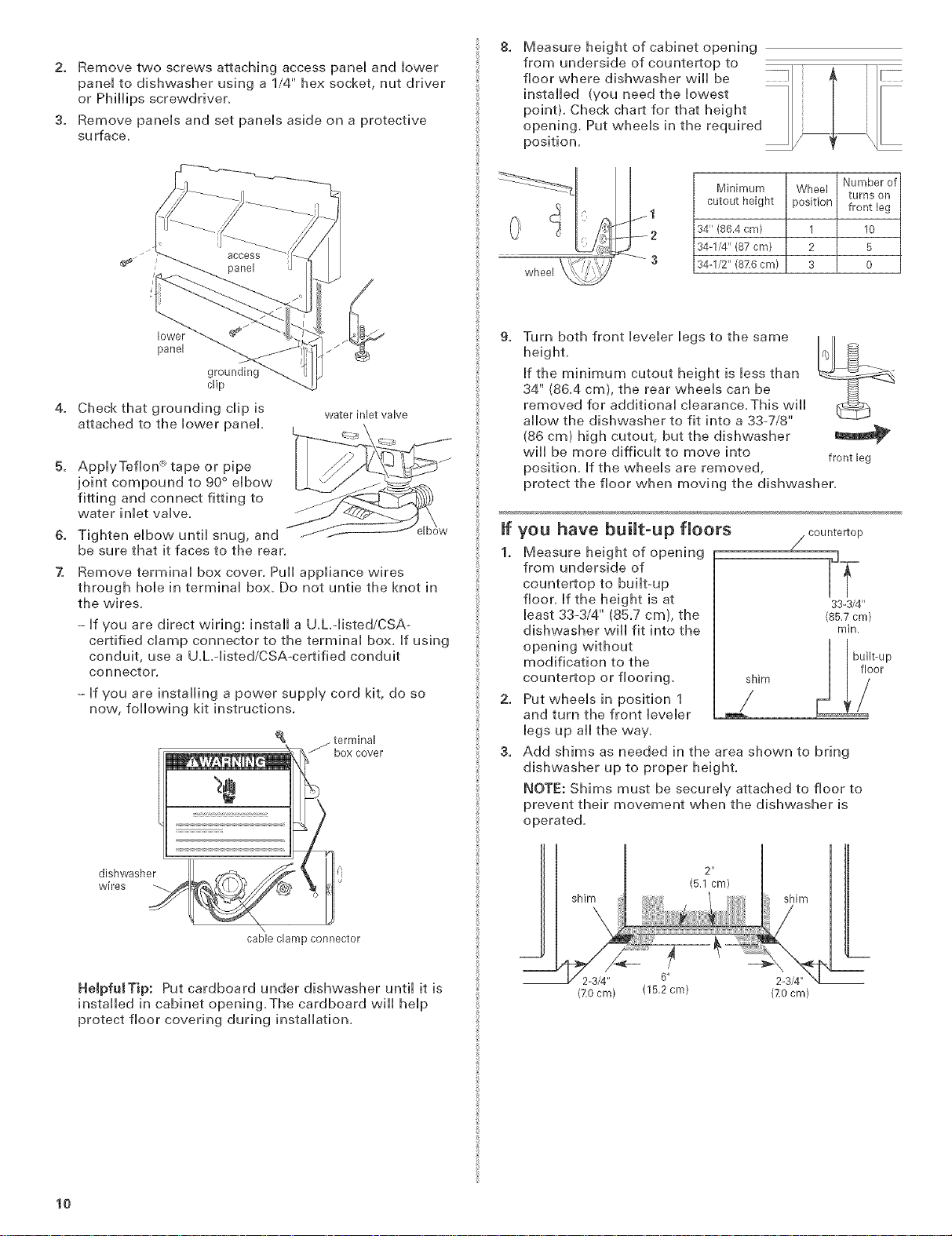
2. Remove two screws attaching access panei and bvver
panei to dishwasher using a 1/4" hex socket, nut driver
or PMHips screwdriven
3. Remove paneis and set paneis aside on a protective
surface,
8. Measure height of cabinet opening
from underside of countertop to
floor where dishwasher will be
installed (you need the lowest
point). Check chart for that height
opening. Put wheels in the required
position.
lower
panel
clip
4. Check that grounding clip is
water inlet valve
attached to the lower panel,
5. ApplyTeflon x tape or pipe
joint compound to 90 ° elbow
fitting and connect fitting to
water inlet valve.
& Tighten elbow until snug, and
be sure that it faces to the rear,
7. Remove terminal box cover. Pull appliance wires
through hole in terminal box. Do not untie the knot in
the wires,
- if you are direct wiring: install a U.h-listed/CSAo
certified clamp connector to the terminal box. if using
conduit, use a U.hqisted/CSAocertified conduit
connector.
- if you are installing a power supply cord kit, do so
nov,,,,following kit instructions,
Minimum Wheel
cutout height position front leg
34" (86.4 cm) 1 10
34-1/4" (87 cm) 2 5
wheel
8,
Turn both front leveler legs to the same
34-I/2" (87.6 cm) 3 0
height.
If the minimum cutout height is less than
34" (86.4 cm), the rear wheels can be
removed for additional clearance.This will
allow the dishwasher to fit into a 33-7/8"
(86 cm) high cutout, but the dishwasher
wiii be more difficult to move into
position, if the wheels are removed,
protect the floor when moving the dishwashen
If you have built-up floors
1. Measure height of opening
/ countertop
from underside of
countertop to built-up
floor, if the height is at
bast 33-3/4" (85.7 cm), the
dishwasher will fit into the
opening without
modification to the
countertop or flooring,
2. Put wheels in position 1
shim &) t°?
and turn the front leveler
legs up all the vva%
3,
Add shims as needed in the area shown to bring
dishwasher up to proper height.
NOTE: Shims must be securely attached to floor to
prevent their movement when the dishwasher is
operated.
Number of
turns on
frontleg
33-3/4"
(85.7 cm)
min.
dishwasher
wires --...
\
cable clamp connector
HeJpfuJTip: Put cardboard under dishwasher until it is
installed in cabinet opening.The cardboard will help
protect floor covering during installation,
lO
shim shim
2-3/4" 6"
(7.0cm) (15,2cm) (ZOcm)
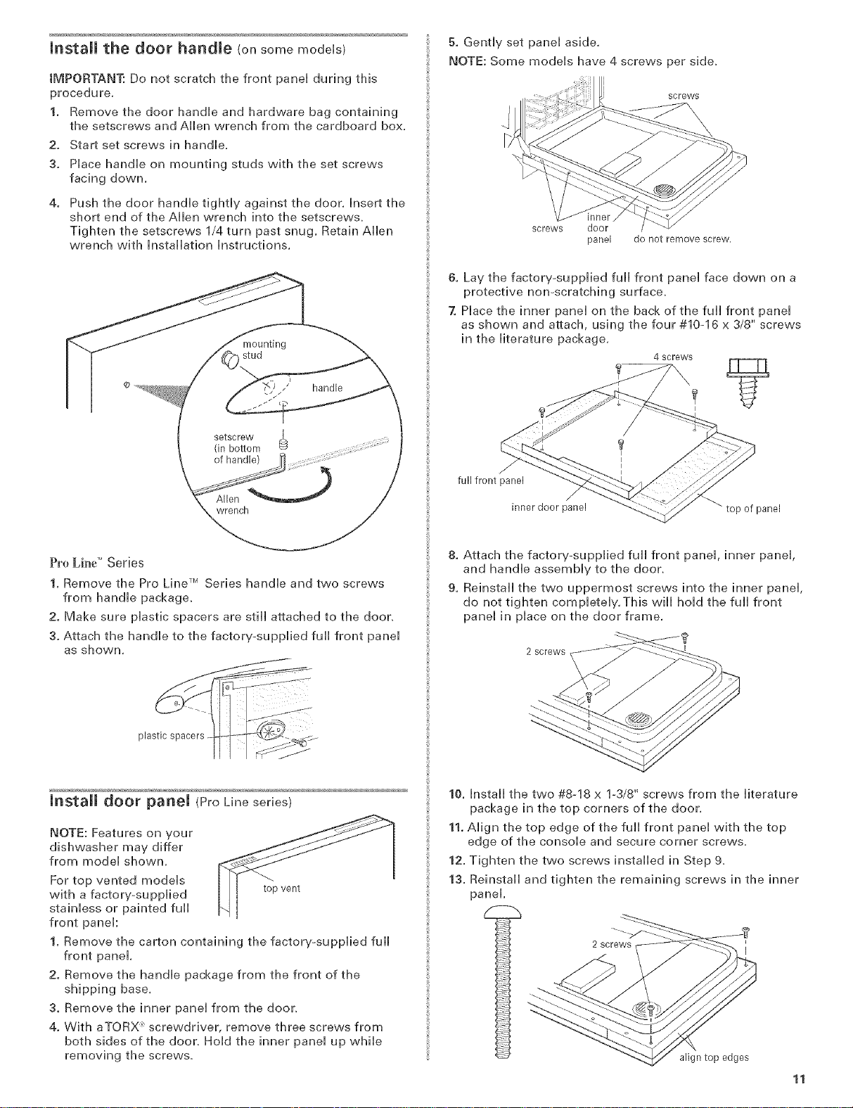
mrmstall the door handle (on some models)
IMPORTANT: Do not scratch the front panel during this
procedure.
1. Remove the door handle and hardware bag containing
the setscrews and Allen wrench from the cardboard box.
2. Start set screws in handle,
3. Place handle on mounting studs with the set screws
facing down.
4. Push the door handle tightly against the door, Insert the
short end of the Allen wrench into the setscrews,
Tighten the setscrews 1/4 turn past snug, Retain Allen
wrench with Installation Instructions,
kg
stud
handle
setscrew
(in bottom
of handle)
.._.)
wrench
5. Gently set panel aside,
NOTE: Some models have 4 screws per side,
screws
screws door
panel do not remove screw,
6. Lay the factory-supplied full front panel face down on a
protective non-scratching surface,
7. Place the inner panel on the back of the full front panel
as shown and attach, using the four #10-16 x 3/8" screws
in the literature package,
4 screws
J
full front panel
inner door panel _ top of panel
Pro Lh_e" Series
1. Remove the Pro Line TM Series handle and two screws
from handle package.
2. Make sure plastic spacers are still attached to the door.
3. Attach the handle to the factory-supplied full front panel
as shown.
mnstaH door panel (ProLine series)
NOTE: Features on your
dishwasher may differ
from model shown.
For top vented models
with a factory-supplied topvent
stainless or painted full
front panel:
1. Remove the carton containing the factory-supplied full
front panel.
2. Remove the handle package from the front of the
shipping base.
3. Remove the inner panel from the door.
4. With aTORX _screwdriver, remove three screws from
both sides of the door. Hold the inner panel up while
removing the screws.
8. Attach the factory-supplied full front panel, inner panel,
and handle assembly to the door.
9. Reinstall the two uppermost screws into the inner panel,
do not tighten completely, This will hold the full front
panel in place on the door frame,
2 screws ,
10. Install the two #8-18 x 1-3/8" screws from the literature
package in the top corners of the door,
11. Align the top edge of the full front panel with the top
edge of the console and secure corner screws,
12. Tighten the two screws installed in Step 9.
13. Reinstall and tighten the remaining screws in the inner
panel,
i 2screws i
align top edges
11
 Loading...