

KitchenAid KUDW02FRWH3, KUDW02FRWH4, KUDW02FRSS3, KUDW02FRSS4, KUDW02FRBL3 Installation Guide
...
KitchenAid _
HOME APPLIANCES
Insta _nInstructions
ndercounter _hwasher
Instructions d'installation
Lave-vaisselle encastre
Table of Contents ............................................................................. 2
Table des matieres ......................................................................... 22
8574116
Table of Contents
Dishwasher Safety ................................. 2
Installation Requirements ........................... 3
Tools and parts ................................. 3
Location Requirements .......................... 3
Drain Requirements ............................. 5
Water Supply Requirements ...................... 5
Electrical Requirements .......................... 5
Installation instructions ............................. 6
Prepare cabinet opening
using existing utility hookups ..................... 6
Prepare cabinet opening
where there are no existing utility hookups .......... 7
Install moisture barrier ........................... 9
Prepare dishwasher ............................ 10
Make electrical connection ...................... 18
Connect to water supply ........................ 19
Connect to drain ............................... 19
Secure dishwasher in cabinet opening ............. 20
Dishwasher Safety
Your safety and the safety of others are very important.
We have provided many important safety messages in this manual and on your appliance. Always read and obey all safety
messages.
This is the safety alert symbol.
This symbol alerts you to potential hazards that can kill or hurt you and others.
All safety messages will follow the safety alert symbol and either the word "DANGER" or "WARNING."
These words mean:
You can be killed or seriously injured if you don't immediately
follow instructions.
You can be killed or seriously injured if you don't follow
instructions.
All safety messages will tell you what the potential hazard is, tell you how to reduce the chance of injury, and tell you what can
happen if the instructions are not followed.
Tip Over Hazard
Do not use dishwasher until completely installed.
Do not push down on open door.
Doing so can result in serious injury or cuts.
You need to:
Slowly open dishwasher door while someone grasps the
rear of the dishwasher. Remove shipping materials, drain
hose and lower rack. Close dishwasher door until latched.
Observe all governing codes and ordinances.
Install this dishwasher as specified in these instructions.
Installation should be performed by a qualified service
technician.The dishwasher must be installed to meet all
electrical and plumbing national and local codes and
ordinances.
Installation Requirements
Location Requirements
Tools and Parts
Gather the required tools and parts before starting
installation.
All installations
Tools needed:
®pliers
oPhillips screwdriver
5/16" and 1/4" nut drivers
or hex sockets
emeasuring tape or ruler
®10" adjustable wrench that
opens to 1-1/8" (2.9 cm)
flat-blade screwdriver
eutility knife
®2 twist-on wire connectors
which are the proper size to
connect your household
wiring to 16-gauge wiring
in dishwasher
small level
_TORX"T15 screwdriver (if
installing custom front
panels)
in addition, for new installations
Tools needed:
* electric drill with 1/2", 3/4"
and 1-1/2" hole saw bits
small tubing cutter
wire stripper
e1-1/2"-2" screw-type clamp
if connecting to waste-tee
Parts supplied
A. 2 - drain hose clamps, 1 large and 1 small
B. 2 - # 10 x 1/2" Phillips-head screws
C. drain hose
_flashlight
shallow pan
5/8" open-end wrench
ebath towel
wood block
Parts needed:
* 90° elbow with 3/8" N.RT.
external threads on one
end. (The other end must
fit your water supply line.)
eTeflon _:tape or pipe joint
compound
* shims (if installed with
built-up floor)
* 4 #10 x 1/2" wood screws
(if installing custom front
panels)
Parts needed:
copper tubing (3/8"
recommended) or flexible
stainless steel braided fill
line
clamp connector or
conduit connector to fit a
7/8" (2.2 cm) diameter hole
Do not run drain lines, water lines or electrical wiring where
they can interfere with or contact dishwasher motor or legs.
The location where the dishwasher will be installed must
provide clearance between motor and flooring. Motor
should not touch the floor.
Do not install dishwasher over carpeted flooring.
Protect dishwasher and water lines leading to dishwasher
against freezing. Damage from freezing is not covered by
the warranty.
A side panel kit is available from your dealer for installing
your dishwasher at the end of your cabinetry.
A moisture barrier accessory (Part No. 4396277) is available
from your dealer for installing underneath the countertop,
but is not required.This may also be obtained by calling
1-800-422-1230.
Check location where dishwasher will be installed.The
location must provide:
o easy access to water, electricity and drain.
convenient access for loading and unloading dishes.
Corner locations require a 2" (5.1 cm) minimum clearance
between the side of the dishwasher door and the wall or
cabinet.
o square opening for proper operation and appearance.
cabinet front perpendicular to floor.
level floor. (If floor at front of opening is not level with
floor at rear of opening, shims may be needed to level
dishwasher.)
NOTE:To prevent shifting during dishwasher operation,
shims must be securely attached to the floor.
If dishwasher will be left unused for a period of time or in a
location where it may be subject to freezing, have it
winterized by authorized service personnel.
Make sure pipes, wires and drain hose are within the
shaded area shown in the "Cutout dimensions" section.
HelpfuITip: If the floor in the dishwasher opening is
uneven (example: tile flooring only partway into
opening) you will need to take special care in measuring
dimensions and in leveling dishwasher.
B
Additional parts supplied with top-venting models only
D. 2 #8 x 1-3/8"TORXR_T15 screws
E. 4 #10 x 3/8" hex-head screws
Additional part supplied with certain models
E Bottom sound pad (located in lower rack)
G. Moisture barrier tape
Make sure all these parts are included. If not included, call
1-800-422-1230.
See separate parts list for accessories available for your
dishwasher.
_PTeflon is a registered trademark of E.I. Du Pont de Nemours and
Company.
_) Registered trademark of TEXTRON.

Product dimensions
Cutout dimensions
3/4" (1.9 cm)--_-
insu lation -
may be
compressed
(not used on
all models)
_-_ 24-7/8" (63.2 cm)
| front vent
=_--- 24-1/2" (62.2 cm)* _ _(___/
_--- 21" (53.3 cm)_,J
SIDE VIEW
All surfaces must be free
from intrusions
3-1/4"
(8.3cm)
r
(5.1 cm) 10"
2-3/4" 3-1/4"
(7 cm) (8.3 cm) (8.3 cm) (7 cm)
Cut holes in shaded area of cabinet walls or floor as specified below:
water line- 1/2" (1.3 cm)
drain line- 1-1/2" (3.8 cm)
direct wire - 3/4" (1.9 cm)
power supply cord- 1-1/2" (3.8 cm)
2"
(5.1cm)
_(15.2 cm)
34"
(86.4 cm)
rain. x
REAR VIEW
Measured from the lowest point on the underside of countertop. May be
reduced to 33-7/6" (86cm) by removing wheels from dishwasher.
r'* Minimum, measured from narrowest point of opening.
_ May be increasedto 6-5/8" (16.6cm) if height of opening is 34-1/2"
(87.6cm) at its lowest point,
Drain Requirements
Electrical Requirements
. Use the new drain hose supplied with your dishwasher.
If this is not long enough, use a new drain hose with a
maximum length of 12 feet (3.7 m) that meets all current
AHAM/IAPMO test standards, is resistant to heat and
detergent, and fits the 1" (2.5 cm) drain connector of the
dishwasher.
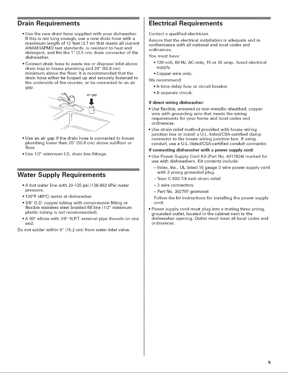
. Connect drain hose to waste tee or disposer inlet above
drain trap in house plumbing and 20" (50.8 cm)
minimum above the floor. It is recommended that the
drain hose either be looped up and securely fastened to
the underside of the counter, or be connected to an air
gap.
C_ ,_ air gap
o Use an air gap if the drain hose is connected to house
plumbing lower than 20" (50.8 cm) above subfloor or
floor.
o Use 1/2" minimum I.D. drain line fittings.
Water Supply Requirements
oA hot water line with 20-120 psi (138-862 kPa) water
pressure.
o 120OF (49oC) water at dishwasher.
o 3/8" O.D. copper tubing with compression fitting or
flexible stainless steel braided fill line (1/2" minimum
plastic tubing is not recommended).
_A 90 ° elbow with 3/8" N.RT. external pipe threads on one
end.
Do not solder within 6" (15.2 cm) from water inlet valve.
Contact a qualified electrician.
Assure that the electrical installation is adequate and in
conformance with all national and local codes and
ordinances.
You must have:
120-volt, 60 Hz, AC-only, 15 or 20 amp., fused electrical
supply.
Copper wire only.
We recommend:
+A time-delay fuse or circuit breaker.
®A separate circuit.
If direct wiring dishwasher:
o Use flexible, armored or non-metallic sheathed, copper
wire with grounding wire that meets the wiring
requirements for your home and local codes and
ordinances.
o Use strain relief method provided with house wiring
junction box or install a U.L,-listed/CSA-certified clamp
connector to the house wiring junction box. If using
conduit, use a U.L,-listed/CSA-certifled conduit connector.
If connecting dishwasher with a power supply cord:
Use Power Supply Cord Kit (Part No. 4317824) marked for
use with dishwashers. Kit contents include:
-Volex, Inc., UL listed 16 gauge 3 wire power supply cord
with 3 prong grounded plug.
- Neer C-500 7/8 inch strain relief.
- 3 wire connectors.
- Part No. 302797 grommet
Follow the kit instructions for installing the power supply
cord.
o Power supply cord must plug into a mating three prong,
grounded outlet, located in the cabinet next to the
dishwasher opening. Outlet must meet all local codes and
ordinances.

installation instructions
Electrical Shock Hazard
Disconnect electrical power at the fuse box or circuit
breaker box before installing dishwasher.
Failure to do so can result in death or electrical shock.
1. Disconnect power.
2. Turn off water supply.
Install the drain hose
IMPORTANT: Always use a new drain hose even when
installing a new replacement dishwasher.
1. Drill a 1-1/2" (3.8 cm) diameter hole in cabinet wall or
floor on the side of the opening closest to the sink.
J L
2. Connect drain hose to waste tee or waste disposer using
one of the following methods:
o Option 1,Waste disposer- with air gap
o Option 2, No waste disposer- with air gap
o Option 3, Waste disposer- no air gap*
o Option 4, No waste disposer- no air gap*
nan air gap is recommended
Prepare cabinet opening using
existing utility hookups
e Follow the steps in this section if you are installing the
dishwasher in an existing cabinet opening with utility
hookups.
e If you are installing the dishwasher in a cabinet opening
that does not have hookups, follow the steps under
"Prepare cabinet opening where there are no existing
utility hookups" section.
line reaches to the
front left of opening
Check that the water ;ter ........
where the water
connection will be e wire
Check that the direct
wire reaches to the _- ............ ____
front right of opening 6" (15.2 cm)
where the electrical
connection will be made.
If the water line and the direct wire reach far enough into
the opening, proceed to the next section "Install the drain
hose:' If they do not reach far enough, follow the steps
under "Prepare cabinet opening where there are no existing
utility hookups:'
direct
HelpfulTip:To reduce the vibration of the hose, keep the
hose away from the floor and the edge of the hole where
it passes through the cabinet.
Option 1:Waste disposer- with air gap:
1. Remove the disposer knockout plug. Cut end of drain
hose if needed (do not cut ribbed section).
2. Attach drain hose to air gap with large spring-type
clamp. If the drain hose was cut, use a 1-1/2" to 2"
(3.8 to 5 cm) screw-type clamp×_
3. Use a rubber hose connector s with spring or screw-type
clamps* to connect air gap to disposer inlet.
This connection must be before the drain trap and at
least 20" (50.8 cm) above the floor where dishwasher will
be installed.
drain hose -
cut hereif needed
rubberhose
connector
large
spring-type
clamp
hose
drain trap
4. Insert drain hose through
hole cut in cabinet to the
front center of opening
where drain connection
will be made.
Parts available from local plumbing supply stores
drain hose
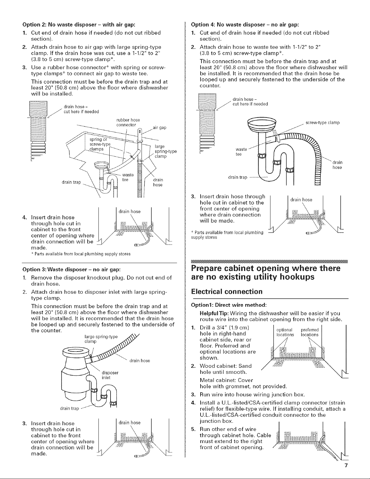
Option 2: No waste disposer - with air gap:
1. Cut end of drain hose if needed (do not cut ribbed
section).
2. Attach drain hose to air gap with large spring-type
clamp. If the drain hose was cut, use a 1-1/2" to 2"
(3.8 to 5 cm) screw-type clamp s.
3. Use a rubber hose connector* with spring or screw-
type clamps* to connect air gap to waste tee.
This connection must be before the drain trap and at
least 20" (50.8 cm) above the floor where dishwasher
will be installed.
drain hose-
cut here if needed
spn_g or
rubber hose
connector
large
spring-type
Option 4: No waste disposer - no air gap:
1. Cut end of drain hose if needed (do not cut ribbed
section).
2. Attach drain hose to waste tee with 1-1/2" to 2"
(3.8 to 5 cm) screw-type clamp x-.
This connection must be before the drain trap and at
least 20" (50.8 cm) above the floor where dishwasher will
be installed. It is recommended that the drain hose be
looped up and securely fastened to the underside of the
counter.
drain hose -
_ cut hereif needed
_ screw-type clamp
Weaste f /,_ _ '_
drain trap hose
drain hose
Insert drain hose
through hole cut in
cabinet to the front
center of opening where
drain connection will be
made.
Parts available from local plumbing supply stores
drain
Option 3: Waste disposer - no air gap:
1. Remove the disposer knockout plug. Do not cut end of
drain hose.
Attach drain hose to disposer inlet with large spring-
type clamp.
This connection must be before the drain trap and at
least 20" (50.8 cm) above the floor where dishwasher
will be installed. It is recommended that the drain hose
be looped up and securely fastened to the underside of
the counter.
large spring-type
clamp
drain hose
disposer
inlet
drain trap
Insert drain hose
drain hose
through hole cut in
cabinet to the front
center of opening where
drain connection will be
made.
drain trap JII
3.
Insert drain hose through
hole cut in cabinet to the
front center of opening
where drain connection
will be made.
Parts available from local plumbing
supply stores
drain hose
Prepare cabinet opening where there
are no existing utility hookups
Electrical connection
Option1: Direct wire method:
HelpfulTip: Wiring the dishwasher will be easier if you
route wire into the cabinet opening from the right side.
1. Drill a 3/4" (1.9 cm) optional preferred
hole in right-hand locations locations
cabinet side, rear or
floor. Preferred and
optional locations are
shown.
2. Wood cabinet: Sand
hole until smooth.
Metal cabinet: Cover
hole with grommet, not provided.
3.
Run wire into house wiring junction box.
4.
Install a U.L.-listed/CSA-certified clamp connector (strain
relief) for flexible-type wire. If installing conduit, attach a
U.L.-listed/CSA-certified conduit connector to the
junction box.
5.
Run other end of wire
through cabinet hole. Cable
must extend to the right
front of cabinet opening.
7
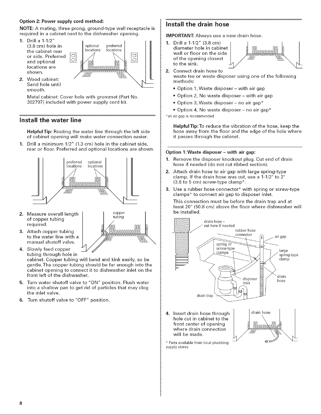
Option 2: Power supply cord method:
NOTE: A mating, three prong, ground-type wall receptacle is
required in a cabinet next to the dishwasher opening.
1. Drill a 1-1/2" I
(3.8 cm) hole in I
or side. Preferred i_-"i
the cabinet rear r.:m [_°ns I°ca_ _i
locationsare
and optional L'_-:_
shown.
optional preferred
2. Wood cabinet:
Sand hole until
smooth.
Metal cabinet: Cover hole with grommet (Part No.
302797) included with power supply cord kit.
install the water line
HelpfulTip: Routing the water line through the left side
of cabinet opening will make water connection easier.
1. Drill a minimum 1/2" (1.3 cm) hole in the cabinet side,
rear or floor. Preferred and optional locations are shown.
2. Measure overall length
of copper tubing
required.
3. Attach copper tubing
to the water line with a
manual shutoff valve.
Slowly feed copper
tubing through hole in
cabinet. Copper tubing will bend and kink easily, so be
gentle.The copper tubing should be far enough into the
cabinet opening to connect it to dishwasher inlet on the
front left of the dishwasher.
Turn water shutoff valve to "ON" position. Flush water
into a shallow pan to get rid of particles that may clog
the inlet valve.
6. Turn shutoff valve to "OFF" position.
copper
tubing
install the drain hose
iMPORTANT: Always use a new drain hose.
1. Drill a 1-1/2" (3.8 cm)
diameter hole in cabinet
wall or floor on the side
of the opening closest
to the sink.
2. Connect drain hose to
waste tee or waste disposer using one of the following
methods:
, Option 1,Waste disposer- with air gap
, Option 2, No waste disposer- with air gap
, Option 3, Waste disposer- no air gap*
, Option 4, No waste disposer- no air gap*
nanair gapis recommended
HelpfulTip:To reduce the vibration of the hose, keep the
hose away from the floor and the edge of the hole where
it passes through the cabinet.
Option 1:Waste disposer- with air gap:
1. Remove the disposer knockout plug. Cut end of drain
hose if needed (do not cut ribbed section).
2. Attach drain hose to air gap with large spring-type
clamp. If the drain hose was cut, use a 1-1/2" to 2"
(3.8 to 5 cm) screw-type clamp*.
3. Use a rubber hose connector s with spring or screw-type
clamps* to connect air gap to disposer inlet.
This connection must be before the drain trap and at
least 20" (50.8 cm) above the floor where dishwasher will
be installed.
drain hose -
cut here if needed
rubber hose
connector
large
spring-type
clamp
hose
drain trap
4. Insert drain hose through
hole cut in cabinet to the
front center of opening
where drain connection
will be made.
Parts available from local plumbing
supply stores
drain hose
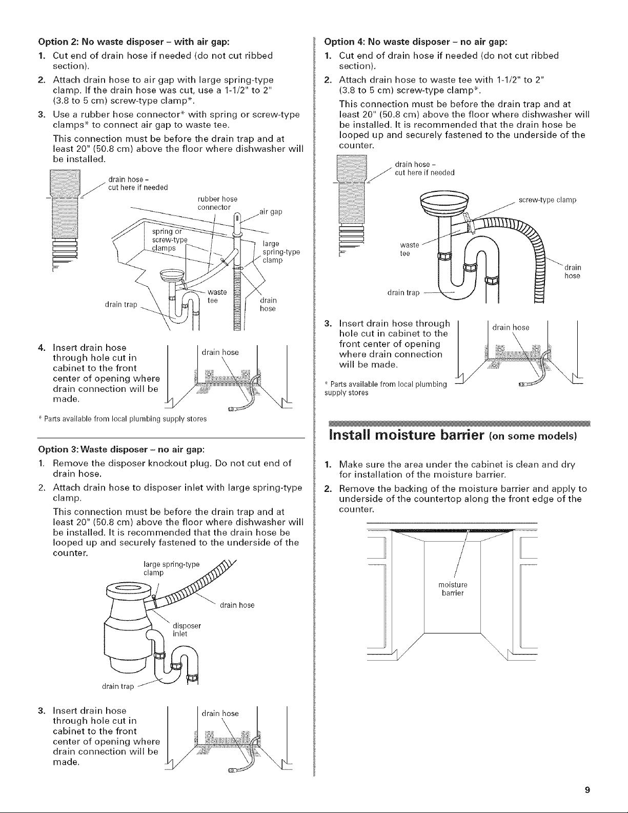
Option2:Nowastedisposer- withair gap:
1. Cut end of drain hose if needed (do not cut ribbed
section).
2. Attach drain hose to air gap with large spring-type
clamp. If the drain hose was cut, use a 1-1/2" to 2"
(3.8 to 5 cm) screw-type clamp*.
3. Use a rubber hose connector* with spring or screw-type
clamps* to connect air gap to waste tee.
This connection must be before the drain trap and at
least 20" (50.8 cm) above the floor where dishwasher will
be installed.
j_ drain hose-
__ cut here if needed
spn_g or
rubber hose
connector
large
spring-type
Option 4: No waste disposer - no air gap:
1. Cut end of drain hose if needed (do not cut ribbed
section).
2. Attach drain hose to waste tee with 1-1/2" to 2"
(3.8 to 5 cm) screw-type clamp x-.
This connection must be before the drain trap and at
least 20" (50.8 cm) above the floor where dishwasher will
be installed. It is recommended that the drain hose be
looped up and securely fastened to the underside of the
counter.
drain hose -
____ cut here if needed
_J screw-type clamp
WeaSte_ __ _ra_en
drain trap hose
Insert drain hose
through hole cut in
cabinet to the front
center of opening where
drain connection will be
made.
r' Parts available from local plumbing supply stores
drain hose
drain
Option 3: Waste disposer - no air gap:
1. Remove the disposer knockout plug. Do not cut end of
drain hose.
Attach drain hose to disposer inlet with large spring-type
clamp.
This connection must be before the drain trap and at
least 20" (50.8 cm) above the floor where dishwasher will
be installed, it is recommended that the drain hose be
looped up and securely fastened to the underside of the
counter.
large spring-type
clamp
dra,n trap -ill
3.
Insert drain hose through
hole cut in cabinet to the
front center of opening
where drain connection
will be made.
Parts available from local plumbing
supply stores
drain hose
Install moisture barrier Ion somemodels}
1. Make sure the area under the cabinet is clean and dry
for installation of the moisture barrier.
2. Remove the backing of the moisture barrier and apply to
underside of the countertop along the front edge of the
counter.
drain trap
Insert drain hose
through hole cut in
cabinet to the front
center of opening where
drain connection will be
made.
disposer
inlet
drain hose
drain hose
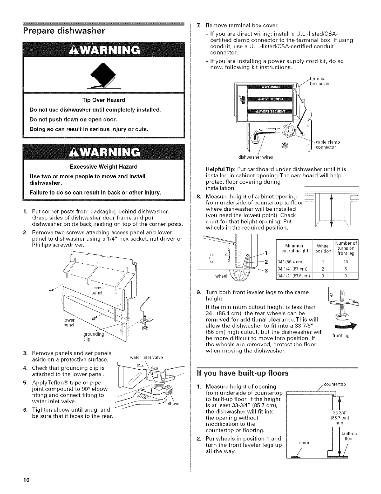
Prepare dishwasher
7. Remove terminal box cover.
- If you are direct wiring: install a U.L.-listed/CSA-
certified clamp connector to the terminal box. If using
conduit, use a U.L-listed/CSA-certified conduit
connector.
- If you are installing a power supply cord kit, do so
now, following kit instructions.
_terminal
box cover
Tip Over Hazard
Do not use dishwasher until completely installed.
Do not push down on open door.
Doing so can result in serious injury or cuts.
Excessive Weight Hazard
Use two or more people to move and install
dishwasher.
Failure to do so can result in back or other injury.
1. Put corner posts from packaging behind dishwasher.
Grasp sides of dishwasher door frame and put
dishwasher on its back, resting on top of the corner posts.
2. Remove two screws attaching access panel and lower
panel to dishwasher using a 1/4" hex socket, nut driver or
Phillips screwdriver.
3
_ cable clamp
dishwasher wires
Helpful Tip: Put cardboard under dishwasher until it is
installed in cabinet opening.The cardboard will help
protect floor covering during
installation.
8=
Measure height of cabinet opening I
from underside of countertop to floor .............II / IIr...........
where dishwasher will be installed II / I I/
(you need the lowest point). Check II / Ill
chart for that height opening. Put _ / ..............._ .................\
wheels in the required position. _ -
/
Minimum Wheel turns on
cutout height position front leg
34" (86.4 cm) 1 10
34-1/4" (87 cm) 2 5
34-1/2" (87.6 cm) 3 0
IiJ connector
Number of
lower
panel
clip
3. Remove panels and set panels
aside on a protective surface.
4. Check that grounding clip is
attached to the lower panel.
5. ApplyTeflon@ tape or pipe
joint compound to 90 ° elbow
fitting and connect fitting to
water inlet valve.
Tighten elbow until snug, and
be sure that it faces to the rear.
water inlet valve
I
9=
Turn both front leveler legs to the same
height.
If the minimum cutout height is less than
34" (86.4 cm), the rear wheels can be
removed for additional clearance.This will
allow the dishwasher to fit into a 33-7/8"
(86 cm) high cutout, but the dishwasher will
be more difficult to move into position. If
the wheels are removed, protect the floor
when moving the dishwasher.
if you have built-up floors
1. Measure height of opening
from underside of countertop
to built-up floor. If the height
is at least 33-3/4" (85.7 cm),
the dishwasher will fit into
the opening without
modification to the
countertop or flooring.
2. Put wheels in position 1 and
turn the front leveler legs up
all the way.
jli,-n L_ _t°_p
front leg
/ countertop
"T
33-3/4"
(85.7cm)
rain.
10

Add shims as needed in the area shown to bring
dishwasher up to proper height.
NOTE: Shims must be securely attached to floor to
prevent their movement when the dishwasher is
operated.
1. Remove the carton containing the factory-supplied full
front panel.
2. Remove the handle package from the front of the
shipping base.
3. With aTORX ®screwdriver, remove three screws on both
sides, as shown; hold the outer panel up while removing
the screws. Save screws for reinstallation.
shim shim
2-3/4" 6" 2__3/4_. --
(70 cm) (15.2cm) (70 cm)
install the door handle (onsome models)
IMPORTANT: Do not scratch the front panel during this
procedure.
1. Remove the door handle and hardware bag containing
the setscrews and Allen wrench from the cardboard box.
2, Start set screws in handle.
3,
Place handle on mounting studs with the set screws
facing down.
4.
Push the door handle tightly against the door. Insert the
short end of the Allen wrench into the setscrews. Tighten
the setscrews 1/4 turn past snug. Retain Allen wrench with
Installation Instructions.
ig
stud
_ ) / handle
T_ 3 screws
I
I
3 screws
outer r
4. Gently set outer panel aside.
5. Lay the factory-supplied full front panel face down on a
protective non-scratching surface.
6. Place the outer panel on the back of the full front panel;
align screw holes.
Attach outer panel to full front panel panel with the four
#10-16 x 3/8" hex head screws supplied in the literature
package.
4 screws
I
I
_h esXrheewad
setscrew
(in bottom
of handle)
wrench
install the door handle--Pro Line _ series
1=
Remove the Pro Lind _'series handle and two screws from
handle package.
2.
Make sure plastic
spacers are still attached
to the door.
Attach the handle to the
factory-supplied full
front panel as shown.
install door panel--Pro Line _ series
For top vented models with a factory-supplied stainless or
painted full front panel:
full front panel
outer panel
edge
8. Attach the panel assembly to the door by reinstalling the
two uppermost side screws; do not tighten screws
completely.This will hold the panel assembly in place on
the door frame.
2 screws
factory-supplied
full front panel
11
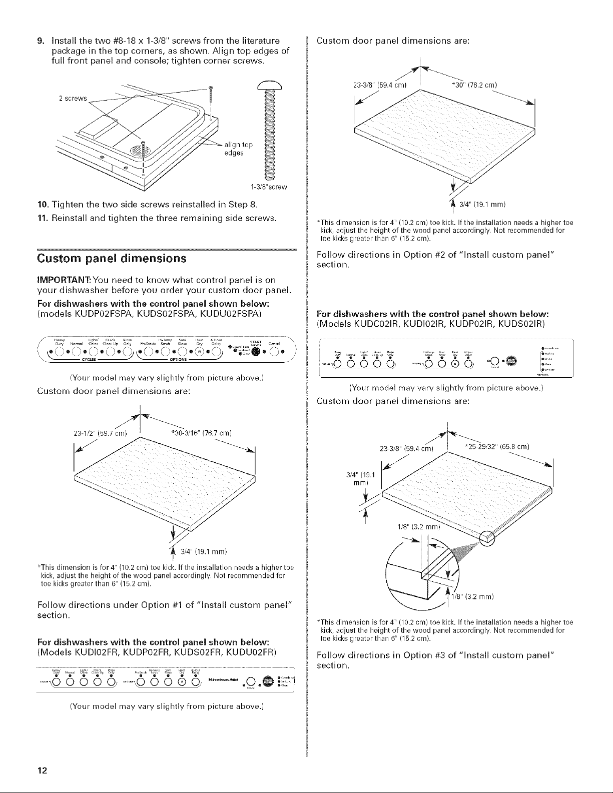
9. Install the two #8-18 x 1-3/8" screws from the literature
package in the top corners, as shown. Align top edges of
full front panel and console; tighten corner screws.
2 screws
I
top
edges
°l
1-3/8"screw
Custom door panel dimensions are:
23-3/8" (59.4 cm) '30" (76.2 cm)
10. Tighten the two side screws reinstalled in Step 8.
11. Reinstall and tighten the three remaining side screws.
Custom panel dimensions
IMPORTANT:You need to know what control panel is on
your dishwasher before you order your custom door panel.
For dishwashers with the control panel shown below:
models KUDP02FSPA, KUDS02FSPA, KUDU02FSPA)
(Your model may vary slightly from picture above.)
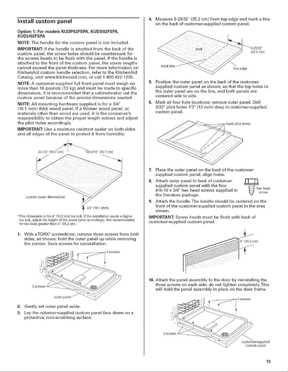
Custom door panel dimensions are:
_ ,, , - ,, ,23 1/2 (597 cm) _30 3/16 (767 cm)
_ 3/4" (19.1 ram)
_This dimension is for 4" (10.2 cm) toe kick. If the installation needs a higher toe
kick, adjust the height of the wood panel accordingly. Not recommended for
toe kicks greater than 6" (15.2 cm).
Follow directions in Option #2 of "Install custom panel"
section.
For dishwashers with the control panel shown below:
(Models KUDC021R, KUDI021R, KUDP021R, KUDS021R)
...... .e i!il
(Your model may vary slightly from picture above.)
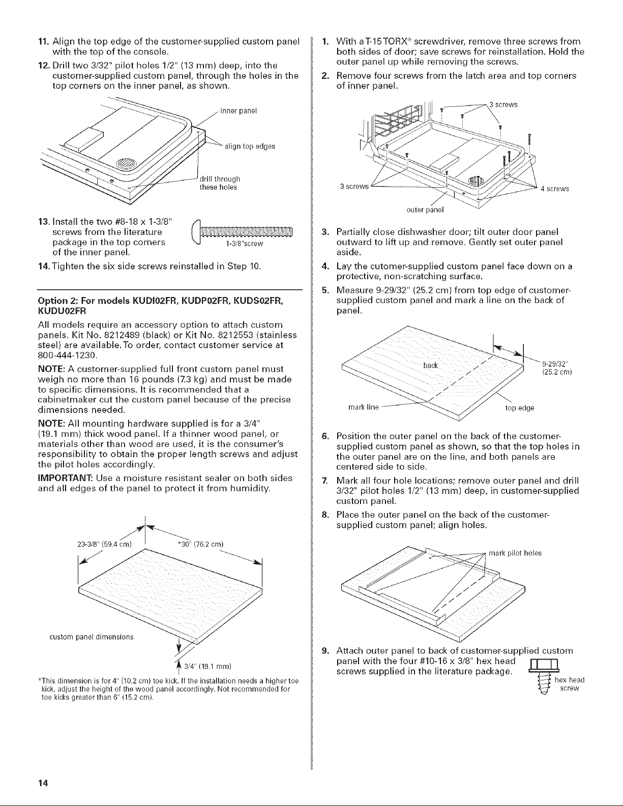
Custom door panel dimensions are:
3/4" (19.1 mm)
*This dimension is for 4" (10.2 cm) toe kick. If the installation needs a higher toe
kick, adjust the height of the wood panel accordingly. Not recommended for
toe kicks greater than 6" (15.2 cm).
Follow directions under Option #1 of "install custom panel"
section.
For dishwashers with the control panel shown below:
(Models KUDIO2FR, KUDPO2FR, KUDSO2FR, KUDUO2FR)
(Your model may vary slightly from picture above.)
12
1/8" (3.2 mm)
_This dimension is for 4" (10.2 cm) toe kick. If the installation needs a higher toe
kick, adjust the height of the wood panel accordingly. Not recommended for
toe kicks greater than 6" (15.2 cm).
Follow directions in Option #3 of "Install custom panel"
section.
Install custom panel
Option 1: For models KUDP02FSPA, KUDS02FSPA,
KUDU02FSPA
NOTE: The handle for the custom panel is not included.
IMPORTANT: If the handle is attached from the back of the
custom panel, the screw holes should be countersunk for
the screws heads to be flush with the panel. If the handle is
attached to the front of the custom panel, the screw lengths
cannot exceed the panel thickness. For more information on
KitchenAid custom handle selection, refer to the KitchenAid
Catalog, visit www.kitchenaid.com, or call 1-800-422-1230.
NOTE: A customer-supplied full front panel must weigh no
more than 16 pounds (7.3 kg) and must be made to specific
dimensions. It is recommended that a cabinetmaker cut the
custom panel because of the precise dimensions needed.
NOTE: All mounting hardware supplied is for a 3/4"
(19.1 ram) thick wood panel, if a thinner wood panel, or
materials other than wood are used, it is the consumer's
responsibility to obtain the proper length screws and adjust
the pilot holes accordingly.
IMPORTANT: Use a moisture resistant sealer on both sides
and all edges of the panel to protect it from humidity.
23-1/2" (59.7cm)F _30-3/16"(76.7cm)
4. Measure 9-29/32" (25.2 cm) from top edge and mark a line
on the back of customer-supplied custom panel.
(25.2 cm)
mark line
5. Position the outer panel on the back of the customer-
supplied custom panel as shown, so that the top holes in
the outer panel are on the line, and both panels are
centered side to side.
top edge
6. Mark all four hole locations; remove outer panel. Drill
3/32" pilot holes 1/2" (13 ram) deep in customer-supplied
custom panel.
mark pilot holes
custom panel dimensions
3/4" (19.1 mm)
_'Thisdimension is for 4" (10.2cm) toe kick. If the installation needs a higher
toe kick, adjust the height of the wood panel accordingly. Not recommended
for toe kicks greater than 6" (15.2cm).
With aTORX ";screwdriver, remove three screws from both
sides, as shown; hold the outer panel up while removing
the screws. Save screws for reinstallation.
3 screws
outer panel
2.
Gently set outer panel aside.
3.
Lay the cutomer-supplied custom panel face down on a
protective, non-scratching surface.
Z Place the outer panel on the back of the customer-
supplied custom panel; align holes.
8. Attach outer panel to back of customer-
supplied custom panel with the four _=_ex head
#10-16 x 3/8" hex head screws supplied in _screw
the literature package.
9. Attach the handle.The handle should be centered on the
front of the customer-supplied custom panel in the area
shown.
iMPORTANT: Screw heads must be flush with back of
customer-supplied custom panel.
10. Attach the panel assembly to the door by reinstalling the
three screws on each side; do not tighten completely.This
will hold the panel assembly in place on the door frame.
3screws
customeFsupplied
custom panel
13
11. Align the top edge of the customer-supplied custom panel
with the top of the console.
12. Drill two 3/32" pilot holes 1/2" (13 ram) deep, into the
customer-supplied custom panel, through the holes in the
top corners on the inner panel, as shown.
inner panel
align top edges
1. With aT-15TORX R,screwdriver, remove three screws from
both sides of door; save screws for reinstallation. Hold the
outer panel up while removing the screws.
2. Remove four screws from the latch area and top corners
of inner panel.
drill through
these holes
13. Install the two #8-18 x 1-3/8"
screws from the literature
package in the top corners
of the inner panel.
14.Tighten the six side screws reinstalled in Step 10.
Option 2: For models KUDIO2FR, KUDPO2FR, KUDSO2FR,
KUDU02FR
All models require an accessory option to attach custom
panels. Kit No. 8212489 (black) or Kit No. 8212553 (stainless
steel) are available.To order, contact customer service at
800-444-1230.
NOTE: A customer-supplied full front custom panel must
weigh no more than 16 pounds (7.3 kg) and must be made
to specific dimensions. It is recommended that a
cabinetmaker cut the custom panel because of the precise
dimensions needed.
NOTE: All mounting hardware supplied is for a 3/4"
(19.1 ram) thick wood panel. If a thinner wood panel, or
materials other than wood are used, it is the consumer's
responsibility to obtain the proper length screws and adjust
the pilot holes accordingly.
IMPORTANT: Use a moisture resistant sealer on both sides
and all edges of the panel to protect it from humidity.
23-3/8" (59.4 cm)__30'' (76.2 cm)
3 screws
outer panel
3. Partially close dishwasher door; tilt outer door panel
outward to lift up and remove. Gently set outer panel
aside.
4. Lay the cutomer-supplied custom panel face down on a
protective, non-scratching surface.
5. Measure 9-29/32" (25.2 cm) from top edge of customer-
supplied custom panel and mark a line on the back of
panel.
mark line top edge
6.
Position the outer panel on the back of the customer-
supplied custom panel as shown, so that the top holes in
the outer panel are on the line, and both panels are
centered side to side.
4 screws
(25.2 cm)
7, Mark all four hole locations; remove outer panel and drill
3/32" pilot holes 1/2" (13 ram) deep, in customer-supplied
custom panel.
8. Place the outer panel on the back of the customer-
supplied custom panel; align holes.
mark pilot holes
custom panel dimensions
,3/4" (19.1 mm)
r'This dimension is for 4" (10.2 cm) toe kick. If the installation needs a higher toe
kick, adjust the height of the wood panel accordingly. Not recommended for
toe kicks greater than 6" (15.2 cm).
14
9. Attach outer panel to back of customer-supplied custom
panel with the four #10-16 x 3/8" hex head rT-'T'I
screws supplied in the literature package.
- ex head
_screw
 Loading...