

Page 1
Installation Instructions
Undercounter Dishwasher
8574116
Instructions d'installation
Lave-vaisselle encastré
®
HOME APPLIANCES
Table of Contents.............................................................................2
Table des matières.........................................................................22
Page 2
You need to:
• Slowly open dishwasher door while someone grasps the
rear of the dishwasher. Remove shipping materials, drain
hose and lower rack. Close dishwasher door until latched.
• Observe all governing codes and ordinances.
• Install this dishwasher as specified in these instructions.
• Installation should be performed by a qualified service
technician. The dishwasher must be installed to meet all
electrical and plumbing national and local codes and
ordinances.
2
Table of Contents
Dishwasher Safety. . . . . . . . . . . . . . . . . . . . . . . . . . . . . . . . . 2
Installation Requirements. . . . . . . . . . . . . . . . . . . . . . . . . . . 3
Tools and parts . . . . . . . . . . . . . . . . . . . . . . . . . . . . . . . . . 3
Location Requirements . . . . . . . . . . . . . . . . . . . . . . . . . . 3
Drain Requirements . . . . . . . . . . . . . . . . . . . . . . . . . . . . . 5
Water Supply Requirements . . . . . . . . . . . . . . . . . . . . . . 5
Electrical Requirements . . . . . . . . . . . . . . . . . . . . . . . . . . 5
Dishwasher Safety
Installation Instructions. . . . . . . . . . . . . . . . . . . . . . . . . . . . . 6
Prepare cabinet opening
using existing utility hookups . . . . . . . . . . . . . . . . . . . . . 6
Prepare cabinet opening
where there are no existing utility hookups. . . . . . . . . . 7
Install moisture barrier . . . . . . . . . . . . . . . . . . . . . . . . . . . 9
Prepare dishwasher . . . . . . . . . . . . . . . . . . . . . . . . . . . . 10
Make electrical connection . . . . . . . . . . . . . . . . . . . . . . 18
Connect to water supply . . . . . . . . . . . . . . . . . . . . . . . . 19
Connect to drain . . . . . . . . . . . . . . . . . . . . . . . . . . . . . . . 19
Secure dishwasher in cabinet opening. . . . . . . . . . . . . 20
Your safety and the safety of others are very important.
We have provided many important safety messages in this manual and on your appliance. Always read and obey all safety
messages.
This is the safety alert symbol.
This symbol alerts you to potential hazards that can kill or hurt you and others.
All safety messages will follow the safety alert symbol and either the word “DANGER” or “WARNING.”
These words mean:
You can be killed or seriously injured if you don't immediately
DANGER
WARNING
All safety messages will tell you what the potential hazard is, tell you how to reduce the chance of injury, and tell you what can
happen if the instructions are not followed.
follow instructions.
can be killed or seriously injured if you don't
You
instructions.
follow
WARNING
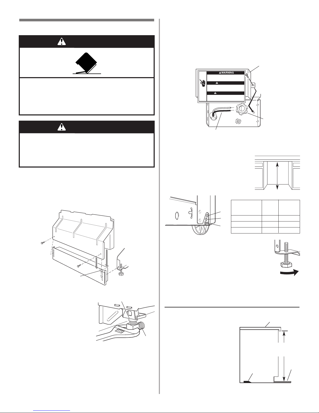
Tip Over Hazard
Do not use dishwasher until completely installed.
Do not push down on open door.
Doing so can result in serious injury or cuts.
Page 3
® Teflon is a registered trademark of E.I. Du Pont de Nemours and
Company.
® Registered trademark of TEXTRON.
Tools needed:
• electric drill with 1/2", 3/4"
and 1-1/2" hole saw bits
• small tubing cutter
• wire stripper
• 1-1/2"-2" screw-type clamp
if connecting to waste-tee
Parts needed:
• copper tubing (3/8"
recommended) or flexible
stainless steel braided fill
line
• clamp connector or
conduit connector to fit a
7/8" (2.2 cm) diameter hole
Tools needed:
• pliers
• Phillips screwdriver
• 5/16" and 1/4" nut drivers
or hex sockets
• measuring tape or ruler
• 10" adjustable wrench that
opens to 1-1/8" (2.9 cm)
• flat-blade screwdriver
• utility knife
• 2 twist-on wire connectors
which are the proper size to
connect your household
wiring to 16-gauge wiring
in dishwasher
• small level
• TORX
®
T15 screwdriver (if
installing custom front
panels)
• flashlight
• shallow pan
• 5/8" open-end wrench
• bath towel
• wood block
Parts needed:
• 90° elbow with 3/8" N.P.T.
external threads on one
end. (The other end must
fit your water supply line.)
• Teflon
®
tape or pipe joint
compound
• shims (if installed with
built-up floor)
• 4 #10 x 1/2" wood screws
(if installing custom front
panels)
Tools and Parts
Gather the required tools and parts before starting
installation.
All installations
In addition, for new installations
A
B
C
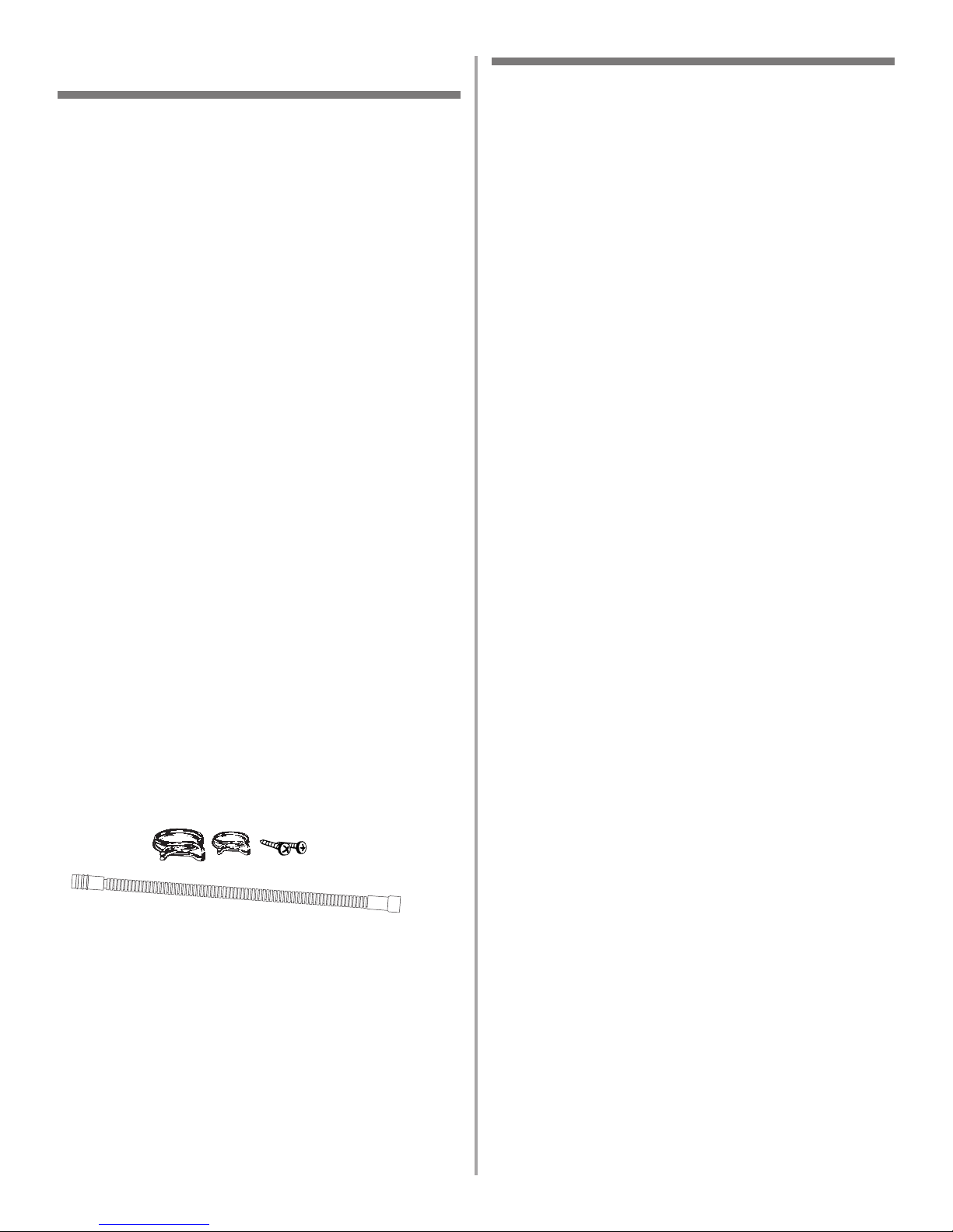
Parts supplied
A. 2 – drain hose clamps, 1 large and 1 small
B. 2 – # 10 x 1/2" Phillips-head screws
C. drain hose
Additional parts supplied with top-venting models only
D. 2 #8 x 1-3/8" TORX
®
T15 screws
E. 4 #10 x 3/8" hex-head screws
Additional part supplied with certain models
F. Bottom sound pad (located in lower rack)
G. Moisture barrier tape
Make sure all these parts are included. If not included, call
1-800-422-1230.
See separate parts list for accessories available for your
dishwasher.
Installation Requirements
3
Location Requirements
Do not run drain lines, water lines or electrical wiring where
they can interfere with or contact dishwasher motor or legs.
The location where the dishwasher will be installed must
provide clearance between motor and flooring. Motor
should not touch the floor.
Do not install dishwasher over carpeted flooring.
Protect dishwasher and water lines leading to dishwasher
against freezing. Damage from freezing is not covered by
the warranty.
A side panel kit is available from your dealer for installing
your dishwasher at the end of your cabinetry.
A moisture barrier accessory (Part No. 4396277) is available
from your dealer for installing underneath the countertop,
but is not required. This may also be obtained by calling
1-800-422-1230.
Check location where dishwasher will be installed. The
location must provide:
• easy access to water, electricity and drain.
• convenient access for loading and unloading dishes.
Corner locations require a 2" (5.1 cm) minimum clearance
between the side of the dishwasher door and the wall or
cabinet.
• square opening for proper operation and appearance.
• cabinet front perpendicular to floor.
• level floor. (If floor at front of opening is not level with
floor at rear of opening, shims may be needed to level
dishwasher.)
NOTE:To prevent shifting during dishwasher operation,
shims must be securely attached to the floor.
If dishwasher will be left unused for a period of time or in a
location where it may be subject to freezing, have it
winterized by authorized service personnel.
Make sure pipes, wires and drain hose are within the
shaded area shown in the “Cutout dimensions” section.
Helpful Tip: If the floor in the dishwasher opening is
uneven (example: tile flooring only partway into
opening) you will need to take special care in measuring
dimensions and in leveling dishwasher.
Page 4
4
9"
(22.9 cm)
10"
(25.4 cm)
6" ***
(15.2 cm)
6" ***
(15.2 cm)
3-1/4"
(8.3 cm)
2-3/4"
(7 cm)
34"
(86.4 cm)
min.*
2"
(5.1 cm)
2"
(5.1 cm)
All surfaces must be free
from intrusions
2"
(5.1 cm)
3-1/4"
(8.3 cm)
3-1/4"
(8.3 cm)
2-3/4"
(7 cm)
3-1/4"
(8.3 cm)
24" (61 cm)
min.
24" (61 cm)
**
Cut holes in shaded area of cabinet walls or floor as specified below:
water line – 1/2" (1.3 cm)
drain line – 1-1/2" (3.8 cm)
direct wire – 3/4" (1.9 cm)
power supply cord – 1-1/2" (3.8 cm)
* Measured from the lowest point on the underside of countertop. May be
reduced to 33-7/8" (86 cm) by removing wheels from dishwasher.
** Minimum, measured from narrowest point of opening.
*** May be increased to 6-5/8" (16.6 cm) if height of opening is 34-1/2"
(87.6 cm) at its lowest point.
Cutout dimensions
5-1/2"
(14 cm)
3-1/2"
(8.9 cm)
Product dimensions
23-7/8" (60.6 cm)
SIDE VIEW
REAR VIEW
24-7/8" (63.2 cm)
3/4" (1.9 cm)
insulation –
may be
compressed
(not used on
all models)
24-1/2" (62.2 cm)*
front vent
21" (53.3 cm)
33-7/8"
(86 cm) min.
with wheels
removed
Page 5

5
Drain Requirements
• Use the new drain hose supplied with your dishwasher.
If this is not long enough, use a new drain hose with a
maximum length of 12 feet (3.7 m) that meets all current
AHAM/IAPMO test standards, is resistant to heat and
detergent, and fits the 1" (2.5 cm) drain connector of the
dishwasher.
• Connect drain hose to waste tee or disposer inlet above
drain trap in house plumbing and 20" (50.8 cm)
minimum above the floor. It is recommended that the
drain hose either be looped up and securely fastened to
the underside of the counter, or be connected to an air
gap.
• Use an air gap if the drain hose is connected to house
plumbing lower than 20" (50.8 cm) above subfloor or
floor.
• Use 1/2" minimum I.D. drain line fittings.
Water Supply Requirements
• A hot water line with 20-120 psi (138-862 kPa) water
pressure.
• 120°F (49°C) water at dishwasher.
• 3/8" O.D. copper tubing with compression fitting or
flexible stainless steel braided fill line (1/2" minimum
plastic tubing is not recommended).
• A 90° elbow with 3/8" N.P.T. external pipe threads on one
end.
Do not solder within 6" (15.2 cm) from water inlet valve.
Electrical Requirements
Contact a qualified electrician.
Assure that the electrical installation is adequate and in
conformance with all national and local codes and
ordinances.
You must have:
• 120-volt, 60 Hz, AC-only, 15 or 20 amp., fused electrical
supply.
• Copper wire only.
We recommend:
• A time-delay fuse or circuit breaker.
• A separate circuit.
If direct wiring dishwasher:
• Use flexible, armored or non-metallic sheathed, copper
wire with grounding wire that meets the wiring
requirements for your home and local codes and
ordinances.
• Use strain relief method provided with house wiring
junction box or install a U.L.-listed/CSA-certified clamp
connector to the house wiring junction box. If using
conduit, use a U.L.-listed/CSA-certified conduit connector.
If connecting dishwasher with a power supply cord:
• Use Power Supply Cord Kit (Part No. 4317824) marked for
use with dishwashers. Kit contents include:
– Volex, Inc., UL listed 16 gauge 3 wire power supply cord
with 3 prong grounded plug.
– Neer C-500 7/8 inch strain relief.
– 3 wire connectors.
– Part No. 302797 grommet
Follow the kit instructions for installing the power supply
cord.
• Power supply cord must plug into a mating three prong,
grounded outlet, located in the cabinet next to the
dishwasher opening. Outlet must meet all local codes and
ordinances.
air gap
Page 6
6
Installation Instructions
1. Disconnect power.
2. Turn off water supply.
Prepare cabinet opening using
existing utility hookups
• Follow the steps in this section if you are installing the
dishwasher in an existing cabinet opening with utility
hookups.
• If you are installing the dishwasher in a cabinet opening
that does not have hookups, follow the steps under
"Prepare cabinet opening where there are no existing
utility hookups" section.
1. Check that the water
line reaches to the
front left of opening
where the water
connection will be
made.
2. Check that the direct
wire reaches to the
front right of opening
where the electrical
connection will be made.
If the water line and the direct wire reach far enough into
the opening, proceed to the next section “Install the drain
hose.“ If they do not reach far enough, follow the steps
under “Prepare cabinet opening where there are no existing
utility hookups.”
6" (15.2 cm)
water
line
direct
wire
Install the drain hose
IMPORTANT: Always use a new drain hose even when
installing a new replacement dishwasher.
1. Drill a 1-1/2" (3.8 cm) diameter hole in cabinet wall or
floor on the side of the opening closest to the sink.
2. Connect drain hose to waste tee or waste disposer using
one of the following methods:
• Option 1, Waste disposer – with air gap
• Option 2, No waste disposer – with air gap
• Option 3, Waste disposer – no air gap*
• Option 4, No waste disposer – no air gap*
*an air gap is recommended
Helpful Tip: To reduce the vibration of the hose, keep the
hose away from the floor and the edge of the hole where
it passes through the cabinet.
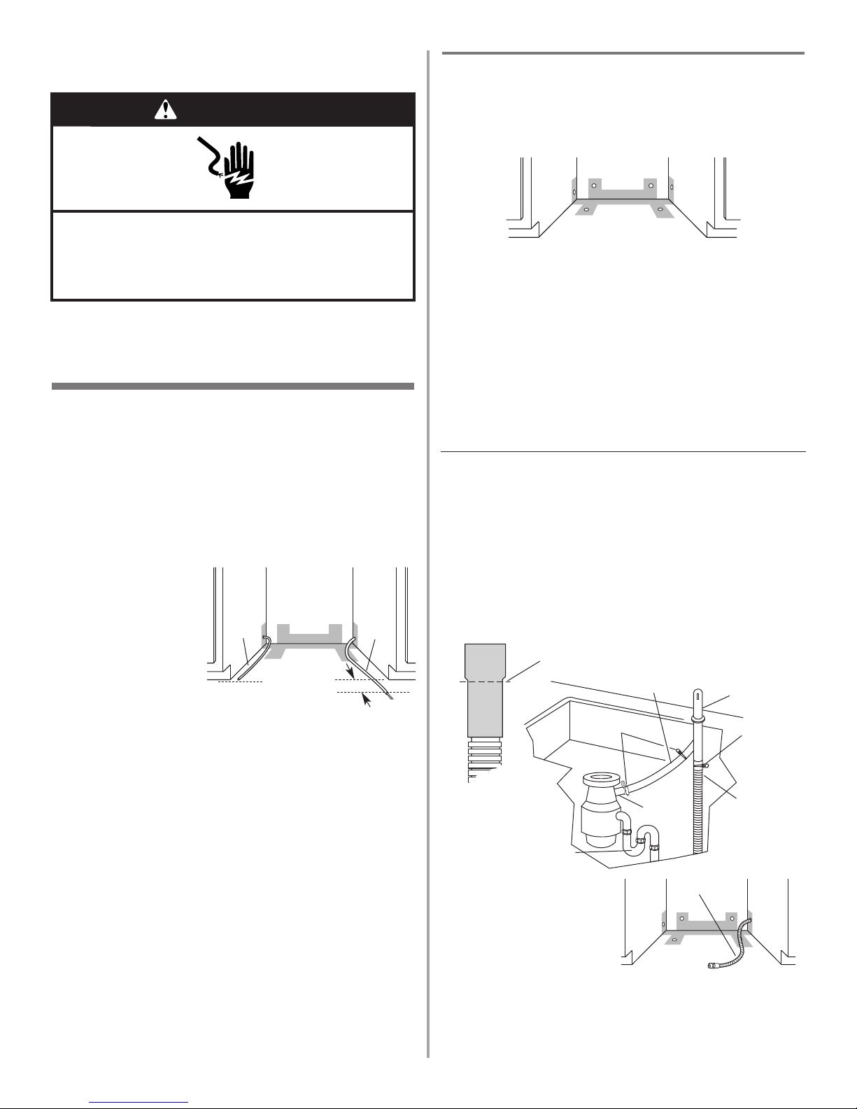
Option 1: Waste disposer – with air gap:
1. Remove the disposer knockout plug. Cut end of drain
hose if needed (do not cut ribbed section).
2. Attach drain hose to air gap with large spring-type
clamp. If the drain hose was cut, use a 1-1/2" to 2"
(3.8 to 5 cm) screw-type clamp*.
3. Use a rubber hose connector* with spring or screw-type
clamps* to connect air gap to disposer inlet.
This connection must be before the drain trap and at
least 20" (50.8 cm) above the floor where dishwasher will
be installed.
4. Insert drain hose through
hole cut in cabinet to the
front center of opening
where drain connection
will be made.
* Parts available from local plumbing supply stores
drain
hose
large
spring-type
clamp
air gap
rubber hose
connector
disposer
inlet
drain trap
drain hose –
cut here if needed
spring or
screw-type
clamps
drain hose
WARNING
Electrical Shock Hazard
Disconnect electrical power at the fuse box or circuit
breaker box before installing dishwasher.
Failure to do so can result in death or electrical shock.
Page 7
7
Prepare cabinet opening where there
are no existing utility hookups
Electrical connection
Option1: Direct wire method:
Helpful Tip: Wiring the dishwasher will be easier if you
route wire into the cabinet opening from the right side.
1. Drill a 3/4” (1.9 cm)
hole in right-hand
cabinet side, rear or
floor. Preferred and
optional locations are
shown.
2. Wood cabinet: Sand
hole until smooth.
Metal cabinet: Cover
hole with grommet, not provided.
3. Run wire into house wiring junction box.
4. Install a U.L.-listed/CSA-certified clamp connector (strain
relief) for flexible-type wire. If installing conduit, attach a
U.L.-listed/CSA-certified conduit connector to the
junction box.
5. Run other end of wire
through cabinet hole. Cable
must extend to the right
front of cabinet opening.
preferred
locations
optional
locations
Option 3: Waste disposer – no air gap:
1. Remove the disposer knockout plug. Do not cut end of
drain hose.
2. Attach drain hose to disposer inlet with large springtype clamp.
This connection must be before the drain trap and at
least 20" (50.8 cm) above the floor where dishwasher
will be installed. It is recommended that the drain hose
be looped up and securely fastened to the underside of
the counter.
3. Insert drain hose
through hole cut in
cabinet to the front
center of opening where
drain connection will be
made.
drain hose
large spring-type
clamp
disposer
inlet
drain trap
Option 4: No waste disposer – no air gap:
1. Cut end of drain hose if needed (do not cut ribbed
section).
2. Attach drain hose to waste tee with 1-1/2" to 2"
(3.8 to 5 cm) screw-type clamp*.
This connection must be before the drain trap and at
least 20" (50.8 cm) above the floor where dishwasher will
be installed. It is recommended that the drain hose be
looped up and securely fastened to the underside of the
counter.
3. Insert drain hose through
hole cut in cabinet to the
front center of opening
where drain connection
will be made.
* Parts available from local plumbing
supply stores
drain
hose
waste
tee
drain trap
screw-type clamp
drain hose –
cut here if needed
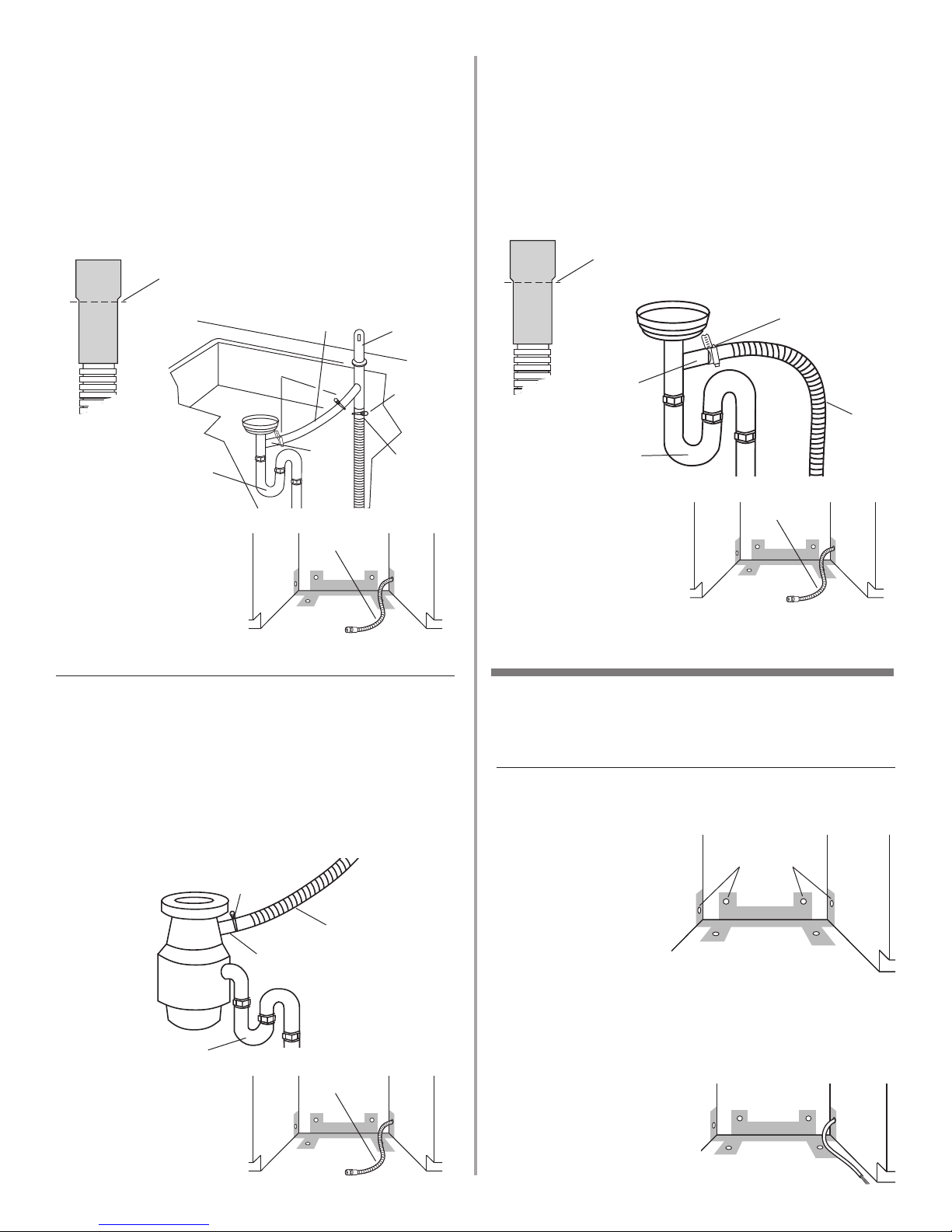
Option 2: No waste disposer – with air gap:
1. Cut end of drain hose if needed (do not cut ribbed
section).
2. Attach drain hose to air gap with large spring-type
clamp. If the drain hose was cut, use a 1-1/2" to 2"
(3.8 to 5 cm) screw-type clamp*.
3. Use a rubber hose connector* with spring or screwtype clamps* to connect air gap to waste tee.
This connection must be before the drain trap and at
least 20" (50.8 cm) above the floor where dishwasher
will be installed.
4. Insert drain hose
through hole cut in
cabinet to the front
center of opening where
drain connection will be
made.
* Parts available from local plumbing supply stores
drain hose –
cut here if needed
drain
hose
large
spring-type
clamp
air gap
rubber hose
connector
spring or
screw-type
clamps
waste
tee
drain trap
drain hose
drain hose
drain hose
Page 8
8
Option 2: Power supply cord method:
NOTE: A mating, three prong, ground-type wall receptacle is
required in a cabinet next to the dishwasher opening.
1. Drill a 1-1/2”
(3.8 cm) hole in
the cabinet rear
or side. Preferred
and optional
locations are
shown.
2. Wood cabinet:
Sand hole until
smooth.
Metal cabinet: Cover hole with grommet (Part No.
302797) included with power supply cord kit.
Install the water line
Helpful Tip: Routing the water line through the left side
of cabinet opening will make water connection easier.
1. Drill a minimum 1/2” (1.3 cm) hole in the cabinet side,
rear or floor. Preferred and optional locations are shown.
2. Measure overall length
of copper tubing
required.
3. Attach copper tubing
to the water line with a
manual shutoff valve.
4. Slowly feed copper
tubing through hole in
cabinet. Copper tubing will bend and kink easily, so be
gentle. The copper tubing should be far enough into the
cabinet opening to connect it to dishwasher inlet on the
front left of the dishwasher.
5. Turn water shutoff valve to “ON” position. Flush water
into a shallow pan to get rid of particles that may clog
the inlet valve.
6. Turn shutoff valve to “OFF” position.
Option 1: Waste disposer – with air gap:
1. Remove the disposer knockout plug. Cut end of drain
hose if needed (do not cut ribbed section).
2. Attach drain hose to air gap with large spring-type
clamp. If the drain hose was cut, use a 1-1/2" to 2"
(3.8 to 5 cm) screw-type clamp*.
3. Use a rubber hose connector* with spring or screw-type
clamps* to connect air gap to disposer inlet.
This connection must be before the drain trap and at
least 20" (50.8 cm) above the floor where dishwasher will
be installed.
4. Insert drain hose through
hole cut in cabinet to the
front center of opening
where drain connection
will be made.
* Parts available from local plumbing
supply stores
copper
tubing
drain
hose
large
spring-type
clamp
air gap
rubber hose
connector
disposer
inlet
drain trap
drain hose –
cut here if needed
spring or
screw-type
clamps
preferred
locations
optional
locations
optional
locations
preferred
locations
Install the drain hose
IMPORTANT: Always use a new drain hose.
1. Drill a 1-1/2” (3.8 cm)
diameter hole in cabinet
wall or floor on the side
of the opening closest
to the sink.
2. Connect drain hose to
waste tee or waste disposer using one of the following
methods:
• Option 1, Waste disposer – with air gap
• Option 2, No waste disposer – with air gap
• Option 3, Waste disposer – no air gap*
• Option 4, No waste disposer – no air gap*
*an air gap is recommended
Helpful Tip: To reduce the vibration of the hose, keep the
hose away from the floor and the edge of the hole where
it passes through the cabinet.
drain hose
Page 9
9
Option 4: No waste disposer – no air gap:
1. Cut end of drain hose if needed (do not cut ribbed
section).
2. Attach drain hose to waste tee with 1-1/2" to 2"
(3.8 to 5 cm) screw-type clamp*.
This connection must be before the drain trap and at
least 20" (50.8 cm) above the floor where dishwasher will
be installed. It is recommended that the drain hose be
looped up and securely fastened to the underside of the
counter.
3. Insert drain hose through
hole cut in cabinet to the
front center of opening
where drain connection
will be made.
* Parts available from local plumbing
supply stores
Install moisture barrier (on some models)
drain
hose
waste
tee
drain trap
screw-type clamp
drain hose –
cut here if needed
Option 2: No waste disposer – with air gap:
1. Cut end of drain hose if needed (do not cut ribbed
section).
2. Attach drain hose to air gap with large spring-type
clamp. If the drain hose was cut, use a 1-1/2" to 2"
(3.8 to 5 cm) screw-type clamp*.
3. Use a rubber hose connector* with spring or screw-type
clamps* to connect air gap to waste tee.
This connection must be before the drain trap and at
least 20" (50.8 cm) above the floor where dishwasher will
be installed.
4. Insert drain hose
through hole cut in
cabinet to the front
center of opening where
drain connection will be
made.
* Parts available from local plumbing supply stores
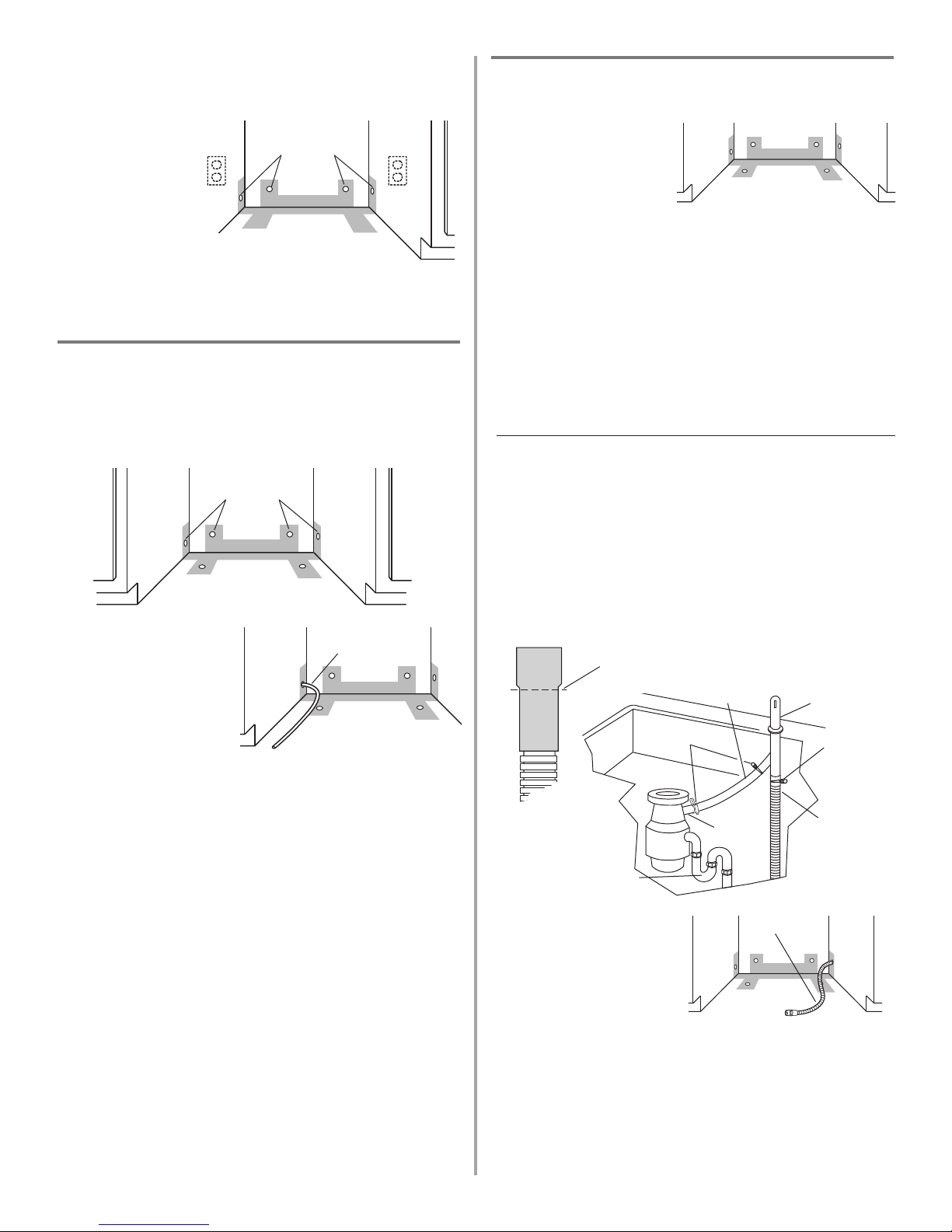
Option 3: Waste disposer – no air gap:
1. Remove the disposer knockout plug. Do not cut end of
drain hose.
2. Attach drain hose to disposer inlet with large spring-type
clamp.
This connection must be before the drain trap and at
least 20" (50.8 cm) above the floor where dishwasher will
be installed. It is recommended that the drain hose be
looped up and securely fastened to the underside of the
counter.
3. Insert drain hose
through hole cut in
cabinet to the front
center of opening where
drain connection will be
made.
drain hose –
cut here if needed
drain
hose
large
spring-type
clamp
air gap
rubber hose
connector
spring or
screw-type
clamps
waste
tee
drain trap
drain hose
large spring-type
clamp
disposer
inlet
drain trap
drain hose
drain hose
drain hose
1. Make sure the area under the cabinet is clean and dry
for installation of the moisture barrier.
2. Remove the backing of the moisture barrier and apply to
underside of the countertop along the front edge of the
counter.
moisture
barrier
Page 10
7. Remove terminal box cover.
– If you are direct wiring: install a U.L.-listed/CSA-
certified clamp connector to the terminal box. If using
conduit, use a U.L.-listed/CSA-certified conduit
connector.
– If you are installing a power supply cord kit, do so
now, following kit instructions.
Helpful Tip: Put cardboard under dishwasher until it is
installed in cabinet opening. The cardboard will help
protect floor covering during
installation.
8. Measure height of cabinet opening
from underside of countertop to floor
where dishwasher will be installed
(you need the lowest point). Check
chart for that height opening. Put
wheels in the required position.
9. Turn both front leveler legs to the same
height.
If the minimum cutout height is less than
34” (86.4 cm), the rear wheels can be
removed for additional clearance. This will
allow the dishwasher to fit into a 33-7/8”
(86 cm) high cutout, but the dishwasher will
be more difficult to move into position. If
the wheels are removed, protect the floor
when moving the dishwasher.
If you have built-up floors
1. Measure height of opening
from underside of countertop
to built-up floor. If the height
is at least 33-3/4” (85.7 cm),
the dishwasher will fit into
the opening without
modification to the
countertop or flooring.
2. Put wheels in position 1 and
turn the front leveler legs up
all the way.
1
2
3
wheel
10
1
2
3
10
5
0
Number of
turns on
front leg
Wheel
position
34" (86.4 cm)
34-1/4" (87 cm)
34-1/2" (87.6 cm)
Minimum
cutout height
front leg
shim
33-3/4"
(85.7 cm)
min.
countertop
built-up
floor
1. Put corner posts from packaging behind dishwasher.
Grasp sides of dishwasher door frame and put
dishwasher on its back, resting on top of the corner posts.
2. Remove two screws attaching access panel and lower
panel to dishwasher using a 1/4” hex socket, nut driver or
Phillips screwdriver.
3. Remove panels and set panels
aside on a protective surface.
4. Check that grounding clip is
attached to the lower panel.
5. Apply Teflon® tape or pipe
joint compound to 90° elbow
fitting and connect fitting to
water inlet valve.
6. Tighten elbow until snug, and
be sure that it faces to the rear.
lower
panel
access
panel
grounding
clip
water inlet valve
elbow
dishwasher wires
cable clamp
connector
terminal
box cover
Prepare dishwasher
WARNING
Tip Over Hazard
Do not use dishwasher until completely installed.
Do not push down on open door.
Doing so can result in serious injury or cuts.
WARNING
Excessive Weight Hazard
Use two or more people to move and install
dishwasher.
Failure to do so can result in back or other injury.
ADVERTENCIA
AVERTISSEMENT
Page 11

7. Attach outer panel to full front panel panel with the four
#10-16 x 3/8" hex head screws supplied in the literature
package.
8. Attach the panel assembly to the door by reinstalling the
two uppermost side screws; do not tighten screws
completely. This will hold the panel assembly in place on
the door frame.
3. Add shims as needed in the area shown to bring
dishwasher up to proper height.
NOTE: Shims must be securely attached to floor to
prevent their movement when the dishwasher is
operated.
11
Install door panel—Pro Line®series
For top vented models with a factory-supplied stainless or
painted full front panel:
2"
(5.1 cm)
6"
(15.2 cm)
2-3/4"
(7.0 cm)
2-3/4"
(7.0 cm)
shim
shim
2 screws
factory-supplied
full front panel
top edge
4 screws
full front panel
outer panel
hex head
screw
Install the door handle (on some models)
IMPORTANT: Do not scratch the front panel during this
procedure.
1. Remove the door handle and hardware bag containing
the setscrews and Allen wrench from the cardboard box.
2. Start set screws in handle.
3. Place handle on mounting studs with the set screws
facing down.
4. Push the door handle tightly against the door. Insert the
short end of the Allen wrench into the setscrews. Tighten
the setscrews 1/4 turn past snug. Retain Allen wrench with
Installation Instructions.
Allen
wrench
setscrew
(in bottom
of handle)
handle
mounting
stud
Install the door handle—Pro Line®series
1. Remove the Pro Line®series handle and two screws from
handle package.
2. Make sure plastic
spacers are still attached
to the door.
3. Attach the handle to the
factory-supplied full
front panel as shown.
plastic spacers
1. Remove the carton containing the factory-supplied full
front panel.
2. Remove the handle package from the front of the
shipping base.
3. With a TORX
®
screwdriver, remove three screws on both
sides, as shown; hold the outer panel up while removing
the screws. Save screws for reinstallation.
4. Gently set outer panel aside.
5. Lay the factory-supplied full front panel face down on a
protective non-scratching surface.
6. Place the outer panel on the back of the full front panel;
align screw holes.
3 screws
3 screws
outer panel
Page 12
Custom door panel dimensions are:
Follow directions in Option #2 of “Install custom panel”
section.
Custom panel dimensions
IMPORTANT: You need to know what control panel is on
your dishwasher before you order your custom door panel.
For dishwashers with the control panel shown below:
(models KUDP02FSPA, KUDS02FSPA, KUDU02FSPA)
(Your model may vary slightly from picture above.)
Custom door panel dimensions are:
Follow directions under Option #1 of “Install custom panel”
section.
For dishwashers with the control panel shown below:
(Models KUDI02FR, KUDP02FR, KUDS02FR, KUDU02FR)
(Your model may vary slightly from picture above.)
3/4" (19.1 mm)
12
*This dimension is for 4" (10.2 cm) toe kick. If the installation needs a higher toe
kick, adjust the height of the wood panel accordingly. Not recommended for
toe kicks greater than 6" (15.2 cm).
23-3/8" (59.4 cm) *30" (76.2 cm)
3/4" (19.1 mm)
*This dimension is for 4" (10.2 cm) toe kick. If the installation needs a higher toe
kick, adjust the height of the wood panel accordingly. Not recommended for
toe kicks greater than 6" (15.2 cm).
23-1/2" (59.7 cm)
*30-3/16" (76.7 cm)
For dishwashers with the control panel shown below:
(Models KUDC02IR, KUDI02IR, KUDP02IR, KUDS02IR)
(Your model may vary slightly from picture above.)
Custom door panel dimensions are:
Follow directions in Option #3 of “Install custom panel”
section.
23-3/8" (59.4 cm)
*25-29/32" (65.8 cm)
3/4" (19.1
mm)
1/8" (3.2 mm)
1/8" (3.2 mm)
*This dimension is for 4" (10.2 cm) toe kick. If the installation needs a higher toe
kick, adjust the height of the wood panel accordingly. Not recommended for
toe kicks greater than 6" (15.2 cm).
9. Install the two #8-18 x 1-3/8" screws from the literature
package in the top corners, as shown. Align top edges of
full front panel and console; tighten corner screws.
10. Tighten the two side screws reinstalled in Step 8.
11. Reinstall and tighten the three remaining side screws.
2 screws
1-3/8"screw
align top
edges
Page 13
Install custom panel
Option 1: For models KUDP02FSPA, KUDS02FSPA,
KUDU02FSPA
NOTE: The handle for the custom panel is not included.
IMPORTANT: If the handle is attached from the back of the
custom panel, the screw holes should be countersunk for
the screws heads to be flush with the panel. If the handle is
attached to the front of the custom panel, the screw lengths
cannot exceed the panel thickness. For more information on
KitchenAid custom handle selection, refer to the KitchenAid
Catalog, visit www.kitchenaid.com, or call 1-800-422-1230.
NOTE: A customer-supplied full front panel must weigh no
more than 16 pounds (7.3 kg) and must be made to specific
dimensions. It is recommended that a cabinetmaker cut the
custom panel because of the precise dimensions needed.
NOTE: All mounting hardware supplied is for a 3/4"
(19.1 mm) thick wood panel. If a thinner wood panel, or
materials other than wood are used, it is the consumer’s
responsibility to obtain the proper length screws and adjust
the pilot holes accordingly.
IMPORTANT: Use a moisture resistant sealer on both sides
and all edges of the panel to protect it from humidity.
1. With a TORX
®
screwdriver, remove three screws from both
sides, as shown; hold the outer panel up while removing
the screws. Save screws for reinstallation.
2. Gently set outer panel aside.
3. Lay the cutomer-supplied custom panel face down on a
protective, non-scratching surface.
*This dimension is for 4" (10.2 cm) toe kick. If the installation needs a higher
toe kick, adjust the height of the wood panel accordingly. Not recommended
for toe kicks greater than 6" (15.2 cm).
13
23-1/2" (59.7 cm) *30-3/16" (76.7 cm)
3/4" (19.1 mm)
custom panel dimensions
4. Measure 9-29/32" (25.2 cm) from top edge and mark a line
on the back of customer-supplied custom panel.
5. Position the outer panel on the back of the customersupplied custom panel as shown, so that the top holes in
the outer panel are on the line, and both panels are
centered side to side.
6. Mark all four hole locations; remove outer panel. Drill
3/32" pilot holes 1/2" (13 mm) deep in customer-supplied
custom panel.
7. Place the outer panel on the back of the customersupplied custom panel; align holes.
8. Attach outer panel to back of customersupplied custom panel with the four
#10-16 x 3/8" hex head screws supplied in
the literature package.
9. Attach the handle. The handle should be centered on the
front of the customer-supplied custom panel in the area
shown.
IMPORTANT: Screw heads must be flush with back of
customer-supplied custom panel.
10. Attach the panel assembly to the door by reinstalling the
three screws on each side; do not tighten completely. This
will hold the panel assembly in place on the door frame.
mark pilot holes
6" (15.2 cm)
hex head
screw
3 screws
3 screws
outer panel
mark line
back
top edge
9-29/32"
(25.2 cm)
customer-supplied
custom panel
3 screws
3 screws
Page 14
1. With a T-15 TORX®screwdriver, remove three screws from
both sides of door; save screws for reinstallation. Hold the
outer panel up while removing the screws.
2. Remove four screws from the latch area and top corners
of inner panel.
3. Partially close dishwasher door; tilt outer door panel
outward to lift up and remove. Gently set outer panel
aside.
4. Lay the cutomer-supplied custom panel face down on a
protective, non-scratching surface.
5. Measure 9-29/32" (25.2 cm) from top edge of customersupplied custom panel and mark a line on the back of
panel.
6. Position the outer panel on the back of the customersupplied custom panel as shown, so that the top holes in
the outer panel are on the line, and both panels are
centered side to side.
7. Mark all four hole locations; remove outer panel and drill
3/32" pilot holes 1/2" (13 mm) deep, in customer-supplied
custom panel.
8. Place the outer panel on the back of the customersupplied custom panel; align holes.
9. Attach outer panel to back of customer-supplied custom
panel with the four #10-16 x 3/8" hex head
screws supplied in the literature package.
Option 2: For models KUDI02FR, KUDP02FR, KUDS02FR,
KUDU02FR
All models require an accessory option to attach custom
panels. Kit No. 8212489 (black) or Kit No. 8212553 (stainless
steel) are available. To order, contact customer service at
800-444-1230.
NOTE: A customer-supplied full front custom panel must
weigh no more than 16 pounds (7.3 kg) and must be made
to specific dimensions. It is recommended that a
cabinetmaker cut the custom panel because of the precise
dimensions needed.
NOTE: All mounting hardware supplied is for a 3/4"
(19.1 mm) thick wood panel. If a thinner wood panel, or
materials other than wood are used, it is the consumer’s
responsibility to obtain the proper length screws and adjust
the pilot holes accordingly.
IMPORTANT: Use a moisture resistant sealer on both sides
and all edges of the panel to protect it from humidity.
23-3/8" (59.4 cm) *30" (76.2 cm)
3/4" (19.1 mm)
11. Align the top edge of the customer-supplied custom panel
with the top of the console.
12. Drill two 3/32" pilot holes 1/2" (13 mm) deep, into the
customer-supplied custom panel, through the holes in the
top corners on the inner panel, as shown.
13. Install the two #8-18 x 1-3/8"
screws from the literature
package in the top corners
of the inner panel.
14.Tighten the six side screws reinstalled in Step 10.
14
drill through
these holes
align top edges
1-3/8"screw
4 screws
outer panel
3 screws
3 screws
*This dimension is for 4" (10.2 cm) toe kick. If the installation needs a higher toe
kick, adjust the height of the wood panel accordingly. Not recommended for
toe kicks greater than 6" (15.2 cm).
mark line
back
top edge
9-29/32"
(25.2 cm)
custom panel dimensions
mark pilot holes
hex head
screw
inner panel
Page 15

NOTE:These dimensions are for frameless custom panel
models with a 4-inch (10.2 cm) console only.
1. With a TORX
®
screwdriver, remove three screws from both
sides of door; hold the outer panel up while removing the
screws.
2. Gently set outer panel aside.
3. Lay the cutomer-supplied custom panel face down on a
protective, non-scratching surface.
4. Position the outer panel on the back of the customersupplied custom panel as shown; make sure top edge of
the outer panel is aligned with the top edge of the
customer-supplied custom panel, and both panels are
centered side to side.
5. Mark all four hole locations; remove outer panel and drill
3/32" pilot holes 1/2" (13 mm) deep, in customer-supplied
custom panel.
10. Attach the panel assembly to the door by reinstalling the
three screws on each side; do not tighten completely. This
will hold the panel assembly in place on the door frame.
11. Align the top edge of the customer-supplied custom panel
with the top of the console.
12. Drill four 1/8" pilot holes 1/2" (13 mm) deep, into the
customer-supplied custom panel, through the holes in the
top corners and latch area of the inner panel.
13. Install the four #8-18
1-3/8" screws along the top
of the inner panel.
14.Tighten the six side screws reinstalled in Step 10.
15. Before installing side trim, clean the sides of door panel.
16. Side trim pieces are held in
place with double-faced
adhesive tape. Make sure
trims are precisedly aligned;
once the trim is installed it
can not be moved.
15
customer-supplied
custom panel
double-faced
tape on inside of
trim
door panel
front
Option 3: For models KUDC02IR, KUDI02IR, KUDP02IR
KUDS02IR
All models require an accessory option to attach custom
panels. Kit No. 8171555 (black), 8171556 (white) or 8171557
(biscuit) are available. To order, call customer service at
800-444-1230.
NOTE: A custom full front panel must weigh no more
than 14 pounds (6.3 kg) and must be made to specific
dimensions. It is recommended that a cabinetmaker cut the
custom panel because of the precise dimensions needed.
IMPORTANT: Use a moisture resistant sealer on both sides
and all edges of the panel to protect it from humidity.
23-3/8" (59.3 cm)
*25-29/32" (65.8 cm)
3/4"
(19.1 mm)
1/8" (3.2 cm)
1/8" (3.2 cm)
*This dimension is for 4" (10.2 cm) toe kick. If the installation needs a higher toe
kick, adjust the height of the wood panel accordingly. Not recommended for
toe kicks greater than 6" (15.2 cm).
customer-supplied
custom panel
align top
edges
mark 4
inner holes
outer panel
3 screws
outer panel
custom panel dimensions
1-3/8"screw
3 screws
3 screws
drill through
these holes
align top edges
inner panel
Page 16

16
score line
plastic
button
bend
tabs
Choose attachment option
Using two or more people, stand the dishwasher up.
Option 1: Countertop
attachment
The dishwasher must be
secured to the cabinet. There
are two brackets on top of the
dishwasher that can be
attached to the countertop if it
is wood, laminate or other
similar surfaces. If this is not
possible, the brackets may be
moved to the sides of the
dishwasher.
NOTE: Do not attach the
dishwasher, this will be done later.
brackets
front vent
model shown
Option 2: Dishwasher side attachment
(for marble, granite or other hard surface countertop)
1. To remove the brackets from the top, flatten tab at back
of brackets with pliers, and pull the brackets out of the
slots.
tabs
2. Break off the end of the bracket along the scored line.
3. Open dishwasher door and place towel over pump
assembly and spray arm of dishwasher. This will prevent
screws from falling into pump area when securing
dishwasher to cabinet.
4. Push the plastic buttons out of the side of the tub.
NOTE: Save the buttons to cover the holes after
dishwasher is installed.
6. Place the outer panel on the back of the customersupplied custom panel and align holes.
7. Attach outer panel to back of customer-supplied custom
panel with four #10 x 1/2" wood screws (not supplied).
If the customer-supplied custom panel is less than 3/4"
(1.9 cm) thick where the screws are attached, shorter
screws maybe required.
8. Attach the panel assembly to the door by reinstalling the
three screws on each side.
3 screws
3 screws
5. Push bracket into slot on the side of dishwasher, and
bend tab in towards the side of the dishwasher so that it
keeps the bracket in place.
NOTE: Do not attach the dishwasher, this will be done
later.
WARNING
Excessive Weight Hazard
Use two or more people to move and install
dishwasher.
Failure to do so can result in back or other injury.
Page 17

4. Check that water line is on the left side of opening and
drain hose is near the center of the hole in the cabinet.
5. Slowly move dishwasher
completely into cabinet opening.
Do not kink or pinch copper
tubing, drain hose, power supply
cord or direct wire between
dishwasher and cabinet.
Helpful Tip: Once the dishwasher
is in position, you may have to
support the front of the
dishwasher by raising, lowering or shimming front feet.
6. Remove cardboard from under dishwasher.
NOTE: It is all right if dishwasher fits tightly into cabinet
opening. Do not remove insulation blanket —the blanket
reduces the sound level.
Level the dishwasher
1. Align front of dishwasher door panel with cabinet doors.
You may need to adjust alignment to be even with your
cabinets.
Helpful Tip: Prop up one side of frame to hold
dishwasher up off floor when adjusting front legs.
2. Check that leveling legs are firmly against the floor.
17
Check door spring tension
1. With another person holding the dishwasher to prevent
it from tipping, open and close the door a few times. If
the door closes or falls open under its own weight, the
door tension will need to be adjusted.
2. To adjust the door spring tension, unhook the spring
from the rear leg of dishwasher.
3. With a 5/16" nut driver or hex socket, remove the screw
from the tensioner.
4. The screw can be put into one of three holes , , in
the front leg of dishwasher. If the door closes by itself,
move the tensioner to a higher number hole and replace
screw. When door is unlatched, if it opens by itself, move
tensioner to a lower numbered hole and replace screw.
5. Re-attach door spring to rear leg. Tensioners on both
sides of dishwasher should be secured at same holes.
Move dishwasher into cabinet opening
1. Grasp the sides of the dishwasher at the edges of the
door panel.
2. Tilt dishwasher backwards on wheels and move
dishwasher close to cabinet opening. Do not push on the
front of the panel or on the console—they may dent.
3. If dishwasher has a power supply cord, insert power
supply cord into hole cut into cabinet.
If using direct wire, check that it is on the right front side
of opening.
screw
tensioner
spring
WARNING
Excessive Weight Hazard
Use two or more people to move and install
dishwasher.
Failure to do so can result in back or other injury.
Page 18

3. Connect the wires as follows using twist-on connectors
sized to connect direct wire to 16-gauge dishwasher
wire:
4. Form bare ground wire into a U-shaped hook. Wrap
ground wire hook clockwise around ground connector
and under the washer.
5. Securely tighten ground connector.
6. Tighten clamp connector or conduit connector screws.
7. Reinstall terminal box cover with wires inside terminal
box. The cover must be outside the box on the left side.
8. Make sure no wires are pinched by cover.
18
3. Close and latch the door, and place level against the
front panel. Check that dishwasher is plumb. If needed,
adjust leveling leg or add shims under rear wheel until
dishwasher is plumb.
4. Repeat for other side of dishwasher.
NOTE: Shims must be securely attached to floor to prevent
their movement when the dishwasher is operated.
5. Place level against top front
opening of tub. Check that
dishwasher is level from side to
side. If dishwasher is not level,
adjust front legs up or down
until dishwasher is level.
Make Electrical Connection
Check “Electrical requirements” section.
You need to:
• have the correct electrical supply and recommended
grounding method.
If you are:
• direct wiring, use Option 1
• using a power supply cord, use Option 2
Option 1: Direct wire method
1. Route direct wire so that it does not touch dishwasher
motor or lower part of dishwasher tub.
2. Pull direct wire through hole in terminal box.
Helpful Tip:
• Select the proper size twist-on
connectors to connect your
household wiring to 16-gauge
dishwasher wiring.
• Insert wire ends into twist-on
connector. Do not pre-twist bare wire.
• Twist connector.
• Gently tug on wires to be sure both
are secured.
ground wire
washer
ground
connector
ground wire
screws
Terminal box wire:
white
black
ground connector
Power supply wire:
white
black
ground wire
WARNING
Electrical Shock Hazard
Electrically ground dishwasher.
Connect ground wire to green ground connector in
terminal box.
Do not use an extension cord.
Failure to follow these instructions can result in death,
fire, or electrical shock.
ADVERTENCIA
AVERTISSEMENT
Page 19

Connect to drain
1. To help minimize vibration, route drain hose to avoid
contact with motor, door springs, water line, cabinet,
flooring or the edge of the hole where it passes through
the cabinet.
2. Do not remove drain loop from side of dishwasher.
3. Place pan under end of drain hose. Pan will collect any
water in drain hose.
4. Place the smaller drain hose clamp onto the small end of
the drain hose.
5. Push the drain hose into the connector up to the stop on
the drain hose.
6. Use pliers to open clamp and slide clamp onto
connector between stops on connector as shown.
19
drain
loop
hose clamp
stop
connector
Option 2: Power supply cord method
1. Plug into a grounded 3 prong outlet.
2. Check that power supply cord does not touch
dishwasher motor or lower part of dishwasher tub.
Connect to water supply
Helpful Tip:
Compression fittings:
a. Slide nut onto copper tubing about 1" (2.5 cm).
b. Slide ferrule onto the tubing. Do not position ferrule
on the end of the tubing.
c. Put the tubing into the elbow as far as it will go.
d. Slide the nut and ferrule forward and start the nut
onto the elbow threads. Be gentle when handling and
positioning the copper tubing, it bends and kinks
easily.
1. To prevent vibration during operation, route the water
supply line so that it does not touch the dishwasher
base, frame or motor.
2. With copper tubing pushed into compression fitting as
far as it will go, use a wrench and tighten compression
fitting nut to elbow on water inlet valve.
3. Place paper towel under elbow. Turn on water supply
and check for leaks.
nut
ferrule
elbow
hose clamp
stops
WARNING
Electrical Shock Hazard
Plug into a grounded 3 prong outlet.
Do not remove ground prong.
Do not use an adapter.
Do not use an extension cord.
Failure to follow these instructions can result in death,
fire, or electrical shock.
Page 20

20
Bottom sound pad installation (on some models)
1. Remove the bottom sound pad from inside the
dishwasher and take it out of the plastic bag.
2. Place pad on the floor in front of the dishwasher, making
sure lettering is facing up and vinyl pad faces down.
3. Fold up and hold the side panels down. Carefully slide
the pad toward the back of the dishwasher as far as it
will go, making sure not to push or pull any wires or
hoses. (Do not force.) Side panels will open to proper
position.
NOTE: If there are pipes or other obstructions coming up
through the floor, you will need to cut a slit in the pad to
fit around the obstacle.
4. Fold the front end of the pad up into position. Make sure
the vinyl pad is tucked up behind the door and the
dishwasher front legs, as shown.
Complete installation
1. Check that grounding clip is attached to the lower panel.
2. Place the lower panel behind the access panel. Some
models have insulation on the access panel which must
fall behind the insulation on the lower panel.
lower
panel
access panel
grounding
clip
Secure dishwasher in cabinet opening
1. If you have not already done so, open dishwasher door
and place towel over pump assembly and spray arm of
dishwasher. This will prevent screws from falling into
pump area when securing dishwasher to countertop.
2. Check that dishwasher is still level and centered side to
side in the opening.
3. Secure dishwasher to countertop or sides of cabinet with
two, #10 x 1/2" Phillips-head screws. The dishwasher
must be secured to keep it from tipping when door is
opened. Do not drop screws into bottom of dishwasher.
4. Open door about 3 inches (7.6 cm) and check that space
between inner door and tub is equal on both sides. If
spacing is not equal, loosen bracket screws and shift tub.
Tighten bracket screws.
5. Check that top of door does not contact screws, brackets,
or countertop. If it does, dishwasher must be lowered
and re-leveled.
6. If securing to sides of cabinet, replace the plastic buttons.
7. Remove towel from dishwasher.
8. Reinstall the lower dishrack.
plastic
button
screw to countertop
screw to
side cabinet
OR
WARNING
Tip Over Hazard
Do not use dishwasher until completely installed.
Do not push down on open door.
Doing so can result in serious injury or cuts.
Page 21

21
Check operation
1. Read the Use and Care Guide that came with your
dishwasher.
2. Check that all parts have been installed and no steps
were skipped.
3. Check that you have all the tools you used.
4. Start dishwasher and allow it to complete the shortest
wash cycle. After the first two minutes, unlatch door,
wait five seconds, then open door.
5. Check to see that there is water in the bottom of the
dishwasher tub. Check that dishwasher is working
properly. If not, see “If dishwasher does not operate”
section.
6. Disconnect power or unplug dishwasher.
If dishwasher does not operate
First try the solutions suggested here to possibly avoid the
cost of a service call.
• Has the circuit breaker tripped or the house fuse blown?
• Is the door closed tightly and latched?
• Has the cycle been set correctly to start the dishwasher?
• Is the water turned on?
If none of these work, call 1-800-422-1230.
3. Hold the two panels together and push them up against
dishwasher leg and vinyl pad.
4. Reinstall the screws through the holes in the access
panel and the slots in the lower panel. Install right side
screw first.
5. Check that the lower edge of the lower panel contacts
the floor.
6. Tighten the screws.
Direct wire method:
Power supply cord method:
7. Reconnect power or plug in dishwasher.
WARNING
Electrical Shock Hazard
Electrically ground dishwasher.
Connect ground wire to green ground connector in
terminal box.
Do not use an extension cord.
Failure to follow these instructions can result in death,
fire, or electrical shock.
WARNING
Electrical Shock Hazard
Plug into a grounded 3 prong outlet.
Do not remove ground prong.
Do not use an adapter.
Do not use an extension cord.
Failure to follow these instructions can result in death,
fire, or electrical shock.
Page 22

22
Tenir compte de ceci :
• Ouvrir lentement la porte du lave-vaisselle tandis qu’une
autre personne saisit l’arrière de l’appareil. Retirer les
matériaux d’emballage, le tuyau de décharge et le panier
inférieur. Fermer la porte du lave-vaisselle et verrouiller le
loquet.
• Respecter les dispositions de tous les codes et règlements
en vigueur.
• Installer le lave-vaisselle conformément aux prescriptions
des présentes instructions.
• L’installation devrait être exécutée par un technicien
qualifié. Veiller à respecter les dispositions de tous les
codes et règlements locaux et nationaux régissant les
installations de plomberie et d’électricité.
Table des matières
Sécurité du lave-vaisselle . . . . . . . . . . . . . . . . . . . . . . . . . .22
Exigences d’installation . . . . . . . . . . . . . . . . . . . . . . . . . . . .23
Outillage et pièces . . . . . . . . . . . . . . . . . . . . . . . . . . . . . 23
Emplacement d’installation . . . . . . . . . . . . . . . . . . . . . . 23
Spécifications de
la canalisation d’évacuation . . . . . . . . . . . . . . . . . . . . . 24
Spécifications de
l’alimentation en eau . . . . . . . . . . . . . . . . . . . . . . . . . . . 24
Spécifications électriques . . . . . . . . . . . . . . . . . . . . . . . 24
Instructions d'installation . . . . . . . . . . . . . . . . . . . . . . . . . . 25
Préparation des ouvertures dans les placards – utilisation
des modes de raccordement existants pour canalisations
et câblage . . . . . . . . . . . . . . . . . . . . . . . . . . . . . . . . . . . . 25
Préparation de l’emplacement d’installation entre les
placards lorsque les canalisations et câbles n’ont pas été
installés . . . . . . . . . . . . . . . . . . . . . . . . . . . . . . . . . . . . . . 26
Installation de la barrière contre l'humidité . . . . . . . . 27
Préparation du lave-vaisselle . . . . . . . . . . . . . . . . . . . . 28
Raccordement électrique . . . . . . . . . . . . . . . . . . . . . . . . 36
Raccordement à la canalisation d’eau . . . . . . . . . . . . . 37
Raccordement à la canalisation d’évacuation . . . . . . . 37
Immobilisation du lave-vaisselle dans l’espace
d’installation . . . . . . . . . . . . . . . . . . . . . . . . . . . . . . . . . . 38
Sécurité du lave-vaisselle
Votre sécurité et celle des autres est très importante.
Nous donnons de nombreux messages de sécurité importants dans ce manuel et sur votre appareil ménager. Assurez-vous de
toujours lire tous les messages de sécurité et de vous y conformer.
Voici le symbole d’alerte de sécurité.
Ce symbole d’alerte de sécurité vous signale les dangers potentiels de décès et de blessures graves à vous
et à d’autres.
Tous les messages de sécurité suivront le symbole d’alerte de sécurité et le mot “DANGER” ou
“AVERTISSEMENT”. Ces mots signifient :
Risque possible de décès ou de blessure grave si vous ne
DANGER
AVERTISSEMENT
Tous les messages de sécurité vous diront quel est le danger potentiel et vous disent comment réduire le risque de blessure et
ce qui peut se produire en cas de non-respect des instructions.
suivez pas immédiatement les instructions.
Risque possible de décès ou de blessure grave si vous
ne suivez pas les instructions.
AVERTISSEMENT
Risque de basculement
Ne pas utiliser le lave-vaisselle jusqu’à ce qu’il soit
complètement installé.
Ne pas appuyer sur la porte ouverte.
Le non-respect de ces instructions peut causer des
blessures graves ou des coupures.
Page 23

23
®Teflon est une marque déposée de Du Pont de Nemours and Company.
®Marque déposée de TEXTRON
Outillage nécessaire :
• perceuse électrique avec
scies à trous de 1/2", 3/4" et
1 1/2"
• petit coupe-tube
• pince à dénuder
• bride de tuyau à vis de 1
1/2" – 2" pour
raccordement à la
canalisation d’égout sur un
raccord T
Pièces nécessaires :
• tube de cuivre (3/8"
recommandé) ou conduit
de raccordement flexible
avec tresse d’acier
inoxydable
• serre-câble ou connecteur
de conduit utilisable sur un
trou de diamètre
2,2 cm (7/8")
Outillage et pièces
Rassembler tous les outils et pièces nécessaires avant de
commencer l’installation.
Pour toutes les configurations d’installation
Outillage et pièces supplémentaires pour
l’installation dans un local neuf
Pièces fournies
A. 2 brides pour tuyau de décharge - 1 grosse, 1 petite
B. 2 vis Phillips n° 10 x 1/2"
C. Tuyau de décharge
Vérifier la présence de toutes ces pièces. Si l’une des pièces
mentionnées n’est pas présente, téléphoner au
1-800-422-1230.
Voir la liste séparée des pièces et accessoires disponibles
pour le lave-vaisselle.
Exigences d’installation
Emplacement d’installation
Ne pas placer canalisation d’évacuation, canalisation d’eau
ou câblage électrique à un endroit où cela susciterait
interférence ou contact avec les pieds ou le moteur du lavevaisselle.
À l’emplacement d’installation du lave-vaisselle, on doit
pouvoir établir le dégagement approprié entre le moteur et
le plancher. Le moteur ne doit pas toucher le plancher.
Ne pas installer le lave-vaisselle par-dessus un tapis.
Protéger du gel le lave-vaisselle et les canalisations d’eau
qui l’alimentent; la garantie de l’appareil ne couvre pas les
dommages imputables au gel.
Un ensemble “panneau latéral” est disponible chez les
revendeurs pour l’installation du lave-vaisselle à l’extrémité
d’une rangée de placards.
Un accessoire pare-vapeur (produit n° 4396277) est
disponible chez les revendeurs pour l’installation de
l’appareil sous le plan de travail. Cependant l’utilisation de
cet accessoire n’est pas indispensable. On peut également
commander ce produit par téléphone au 1-800-422-1230.
Inspecter l’emplacement d’installation du lave-vaisselle; il
doit comporter les caractéristiques suivantes :
• facilité d’accès aux canalisations d’eau et d’égout et à la
source d’électricité.
• accès facile pour chargement et déchargement de la
vaisselle. Dans le cas de l’installation dans un angle, on
doit pouvoir établir un dégagement de 5,1 cm (2") ou plus
entre le côté de la porte du lave-vaisselle et le mur ou le
placard.
• ouverture carrée offrant l’esthétique appropriée et
permettant un fonctionnement correct.
• façade des placards perpendiculaire au plancher.
• plancher horizontal et plat (s’il y a un écart de niveau entre
l’avant et l’arrière sur le plancher de l’emplacement
d’installation, il pourrait être nécessaire d’utiliser des cales
pour établir l’aplomb de l’appareil).
NOTE : Pour éviter tout déplacement des cales durant le
fonctionnement de l’appareil, il est nécessaire de fixer les
cales au plancher.
Si le lave-vaisselle ne doit pas être utilisé pendant une
période prolongée ou s’il est laissé à un endroit qui pourrait
être exposé au gel, veiller à faire exécuter les opérations de
pré-hivernage par un technicien compétent.
Veiller à ce que les canalisations d’eau et d’évacuation et les
câbles électriques soient dans la zone marquée en gris dans
la section “Dimensions de l’emplacement d’installation”.
Conseil utile : Si le plancher de l’espace d’installation
n’est pas parfaitement horizontal et plat (exemple :
garnissage de carrelage sur une partie seulement), on
devra accorder une attention particulière aux détails lors
du relevé des dimensions, pour pouvoir établir l’aplomb
correct du lave-vaisselle.
Outillage nécessaire :
• pince
• tournevis Phillips
• tourne-écrou ou clé à
douille – douilles
hexagonales de 5/16" ou
1/4"
• mètre-ruban ou règle
• clé à molette de 10"
(ouverture jusqu’à 2,9 cm
[1 1/8"])
• tournevis à lame plate
• couteau utilitaire
• 2 connecteurs de fils de
taille appropriée pour le
raccordement des
conducteurs de l’appareil
(calibre 16) au câblage de
la maison
• petit niveau
• tournevis TORX
®
T15
(en cas d’installation de
panneaux avant
personnalisés)
• lampe torche
• plat peu profond
• clé plate de 5/8"
• serviette de bain
• cale de bois
Pièces nécessaires :
• raccord 90° avec filetage
externe de 3/8" NPT à une
extrémité. (La configuration
de l’autre extrémité doit
être adaptée à celle de la
canalisation d’arrivée
d’eau.)
• ruban de Teflon
®
ou
composé d’étanchéité pour
tuyauteries
• cales (pour l’installation sur
un plancher à
rehaussement partiel)
• 4 vis à bois n° 10 x 1/2"
(en cas d’installation de
panneaux avant
personnalisés)
C
A
B
Pièces additionnelles fournies uniquement avec les modèles
à évacuation par le haut
D. 2 vis n° 8 x 1-3/8" TORX
®
T15
E. 4 vis à tête hexagonale n° 10 x 3/8"
Pièces supplémentaires fournies avec certains modèles
F. Coussinet du bas (situé dans le panier inférieur)
G. Barrière contre l'humidité
Page 24

24
22,9 cm
(9")
25,4 cm
(10")
15,2 cm
(6") ***
15,2 cm
(6") ***
8,3 cm
(3-1/4")
7 cm
(2-3/4")
86,4 cm
(34")
min.*
5,1 cm
(2")
5,1 cm
(2")
toutes les surfaces doivent
être exemptes de
protubérances.
5,1 cm
(2")
8,3 cm
(3-1/4")
8,3 cm
(3-1/4")
7 cm
(2-3/4")
8,3 cm
(3-1/4")
61 cm (24")
min.
61 cm (24")
**
Découper les trous dans la zone marquée en gris du plancher, du mur ou des
parois des placards, selon les spécifications ci-dessous :
Canalisation d’eau – 1,3 cm (1/2")
Canalisation d’évacuation – 3,8 cm (1-1/2")
Câble pour câblage direct – 1,9 cm (3/4")
Cordon d’alimentation – 3,8 cm (1-1/2")
* Mesure depuis le point le plus bas de la face inférieure du plan de travail.
Cette dimension peut être réduite à 86 cm (33-7/8") si on retire les roues
du lave-vaisselle.
** Dimension minimale mesurée au point le plus étroit de l’ouverture.
*** Cette dimension peut être portée à 16,6 cm (6-5/8") si la hauteur de
l’ouverture est de 87,6 cm (34-1/2") au point le plus bas.
Dimensions de l’espace d’installation
14 cm
(5-1/2")
8,9 cm
(3-1/2")
Dimensions du produit
60,6 cm (23-7/8")
1,9 cm (3/4")
le matériau
isolant (pas
utilisé sur tous
les modèles)
pourrait être
comprimé
62,2 cm (24-1/2")*
63,2 cm (24-7/8")*
évent avant
VUE LATÉRALE
VUE ARRIÈRE
53,3 cm (21")
86 cm (33-7/8")
min., avec
roues enlevées
Page 25

25
Spécifications de la canalisation
d’évacuation
• Utiliser le tuyau d’évacuation neuf fourni avec le lave-
vaisselle. Si ce tuyau n’est pas suffisamment long, utiliser
un tuyau d’évacuation neuf de longueur maximale 3,7 m
(12 pi) qui satisfait les critères de la norme AHAM/IAPMO
en vigueur, résistant à la chaleur et aux détergents, et qui
pourra être connecté sur le raccord de sortie de 2,5 cm
(1") du lave-vaisselle.
• Connecter le conduit d’évacuation à la canalisation
d’égout par l’intermédiaire d’un raccord T ou du raccord
d’un broyeur à déchets situé plus haut que le siphon du
circuit de plomberie de la maison, et à au moins 50,8 cm
(20") au-dessus du sol. On recommande de lover le tuyau
d’évacuation et de le fixer solidement sur la face
inférieure du plan de travail, ou de le raccorder à un
dispositif brise-siphon.
• Utiliser un dispositif brise-siphon si le tuyau d’évacuation
est connecté à la canalisation d’égout de la maison à
moins de 50,8 cm (20") au-dessus du sous-plancher ou du
plancher.
• Utiliser un raccord de diamètre intérieur de 1/2" ou plus.
Spécifications de l’alimentation en eau
• Canalisation d’eau chaude, sous pression de 20 à 120
lb/po
2
(138–862 kPa).
• Température de 49°C (120°F) à l’entrée du lave-vaisselle.
• Canalisation de cuivre de diamètre externe 3/8" avec
raccord à compression, ou conduit de raccordement
flexible à tresse d’acier inoxydable (l’emploi d’un tube de
plastique de 1/2" minimum est possible, mais
déconseillé).
• raccord 90° avec filetage externe de 3/8" NPT à une
extrémité.
Ne pas exécuter de raccordement par soudure à moins de
15,2 cm (6") de l’électrovanne d’admission d’eau.
Spécifications électriques
Contacter un électricien qualifié.
Vérifier que l’installation électrique est adéquate et qu’elle
satisfait les exigences de tous les codes et règlements
locaux et nationaux en vigueur.
Caractéristiques exigées :
• 120 volts CA seulement,, 60 Hz; protection par fusible
15 ou 20 A.
• conducteurs de cuivre seulement
On recommande :
• un fusible temporisé ou disjoncteur.
• une alimentation par un circuit indépendant.
Pour le raccordement direct du lave-vaisselle :
• Utiliser un câble flexible blindé ou à gaine non
métallique, des conducteurs de cuivre avec liaison à la
terre, satisfaisant les exigences des codes et règlements
locaux.
• Arrimer le câble avec le dispositif fourni sur la boîte de
connexion de la maison, ou installer un serre-câble
(homologation UL ou CSA) sur la boîte de connexion de
la maison. Dans le cas de l’emploi d’un conduit, utiliser
un connecteur de conduit (homologation UL ou CSA).
Alimentation de l’appareil par un cordon d’alimentation :
• Utiliser le cordon d’alimentation (produit n° 4317824)
identifié pour l’utilisation avec un lave-vaisselle.
L’ensemble comprend :
- cordon d’alimentation Volex Inc., avec 3 conducteurs
de calibre 16 (homologation UL) et fiche de
branchement à 3 broches pour liaison à la terre.
- serre-câble 7/8" Neer C-500
- 3 connecteurs de fils
- bague de protection n° 302797
Pour l’installation du cordon d’alimentation, procéder
conformément aux instructions fournies avec
l’ensemble.
• La fiche du cordon d’alimentation devra être branchée sur
une prise de courant à 3 alvéoles de configuration
correspondante, reliée à la terre, installée dans le placard
à côté de l’emplacement d’installation du lave-vaisselle.
La prise de courant doit satisfaire les exigences de tous
les codes et règlements locaux.
brise-siphon
Page 26

26
Instructions d’installation
1. Interrompre l’alimentation électrique.
2. Fermer l’arrivée d’eau.
Préparation des ouvertures dans les
placards – utilisation des modes de
raccordement existants pour
canalisations et câblage
• Procéder conformément aux instructions de cette section
pour l’installation de l’appareil à un emplacement déjà
doté de moyens de raccordement.
• Pour l’installation de l’appareil à un emplacement où les
canalisations et le câblage n’ont pas déjà été installés,
procéder
conformément aux
instructions
présentées à la
section “Préparation
de l’emplacement
d’installation entre
les placards lorsque
les canalisations et
câbles n’ont pas été
installés”.
1. Vérifier que la canalisation d’eau atteint le côté avant
gauche de l’espace d’installation (endroit où le
raccordement à l’appareil sera effectué).
2. Vérifier que le câble d’alimentation atteint l’angle avant
droit de l’espace d’installation (endroit où le
raccordement à l’appareil sera effectué).
Si la canalisation d’eau et le câble de raccordement
électrique sont suffisamment longs, passer à la section
suivante “Installation du tuyau d’évacuation”. Si la
canalisation d’eau et le câble électrique ne sont pas
suffisamment longs, procéder conformément aux
instructions de la section “Préparation de l’emplacement
d’installation entre les placards lorsque les canalisations et
câbles n’ont pas été installés”.
15,2 cm (6")
canalisation
d’eau
câble pour
raccordement direct
Installation du tuyau d’évacuation
IMPORTANT : On doit toujours utiliser un tuyau
d’évacuation neuf, même pour l’installation d’un lavevaisselle de remplacement.
1. Percer un trou de diamètre 3,8 cm (1 1/2") dans la paroi
du placard ou dans le plancher sur le côté de l’espace
d’installation le plus proche de l’évier.
2. Employer l’une des méthodes suivantes pour raccorder
le tuyau d’évacuation sur un raccord T ou sur un broyeur
à déchets.
• Option 1 - broyeur à déchets – avec brise-siphon
• Option 2 - pas de broyeur à déchets – avec brise-siphon
• Option 3 - broyeur à déchets – sans brise-siphon*
• Option 4 - pas de broyeur à déchets – sans brisesiphon*
* on recommande qu’un brise-siphon soit disponible
Conseil utile : Pour réduire les effets de vibration du
tuyau durant le fonctionnement, maintenir une
séparation entre le tuyau et le plancher et entre le tuyau
et la circonférence du trou de passage à travers le
placard.
Option 1 - broyeur à déchets – avec brise-siphon :
1. Ôter l’opercule arrachable sur le broyeur à déchets. Si
nécessaire, couper l’extrémité du tuyau d’évacuation (ne
pas couper dans la section ondulée).
2. Connecter le tuyau d’évacuation sur le dispositif brisesiphon avec la grosse bride à ressort. Si le tuyau
d’évacuation a été coupé, utiliser une bride à vis* de 3,8
à 5 cm (1 1/2 à 2").
3. Utiliser un raccord en caoutchouc* avec une bride à
ressort ou à vis* pour raccorder le dispositif brisesiphon à l’entrée du broyeur à déchets.
Ce raccordement doit être réalisé en amont du siphon du
circuit d’évacuation et à au moins 50,8 cm (20")
au-dessus du plancher de l’espace d’installation du
lave-vaisselle.
4. Insérer le tuyau d’évacuation à
travers le trou découpé dans le
placard et acheminer le tuyau
jusqu'à l'angle avant droit de
l'ouverture où le raccordement
du circuit d'évacuation sera
réalisé.
*Pièces disponibles dans un magasin local de fournitures de plomberie
tuyau
d’évacuation
grosse bride
à ressort
dispositif
brise-siphon
raccord en
caoutchouc
entrée du
broyeur à
déchets
siphon du circuit
d’évacuation
tuyau d’évacuation
couper ici si nécessaire
brides à
ressort
ou à vis
tuyau d’évacuation
AVERTISSEMENT
Risque de choc électrique
Interrompre l'alimentation électrique avant d'installer
le lave-vaisselle (au niveau du tableau de distribution fusible ou disjoncteur)
Le non-respect de cette instruction peut causer
un décès ou un choc électrique.
Page 27

27
Option 3 - broyeur à déchets – sans brise-siphon :
1. Ôter l’opercule arrachable du broyeur à déchets. Ne pas
couper l’extrémité du tuyau d’évacuation.
2. Connecter le tuyau d’évacuation sur le broyeur à déchets
avec la grosse bride à ressort.
Ce raccordement doit être réalisé en amont du siphon du
circuit d’évacuation et à au moins 50,8 cm (20") au-dessus
du plancher de l’espace d’installation du lave-vaisselle. On
recommande de lover le tuyau d’évacuation et de le fixer
solidement sur la face inférieure du plan de travail.
3. Insérer le tuyau d’évacuation à
travers le trou découpé dans
le placard et acheminer le
tuyau jusqu'à l'angle avant
droit de l'ouverture où le
raccordement du circuit
d'évacuation sera réalisé.
tuyau
d’évacuation
grosse bride
à ressort
entrée du
broyeur à déchets
siphon du circuit
d’évacuation
Option 4 - pas de broyeur à déchets – sans brise-siphon :
1. Si nécessaire, couper l’extrémité du tuyau d’évacuation
(ne pas couper dans la section ondulée).
2. Connecter le tuyau d’évacuation sur le raccord T du circuit
d’évacuation avec une bride à vis* de 3,8 à 5 cm
(1 1/2 à 2")*.
Ce raccordement doit être réalisé en amont du siphon du
circuit d’évacuation et à au moins 50,8 cm (20")
au-dessus du plancher de l’espace d’installation du lavevaisselle. On recommande de lover le tuyau d’évacuation
et de le fixer solidement sur la face inférieure du plan de
travail.
3. Insérer le tuyau d’évacuation à
travers le trou découpé dans le
placard et acheminer le tuyau
jusqu’à l’emplacement de
raccordement au lave-vaisselle.
* Pièces disponibles dans un magasin local de fournitures de plomberie
tuyau
d’évacuation
raccord T
du circuit
d’évacuation
siphon du circuit
d’évacuation
grosse bride à vis
tuyau d’évacuation
couper ici si nécessaire
Option 2 - pas de broyeur à déchets – avec brise-siphon :
1. Si nécessaire, couper l’extrémité du tuyau d’évacuation
(ne pas couper dans la section ondulée).
2. Connecter le tuyau d’évacuation sur le dispositif brisesiphon avec la grosse bride à ressort. Si le tuyau
d’évacuation a été coupé, utiliser une bride à vis* de 3,8
à 5 cm (1 1/2 à 2").
3. Utiliser un raccord de caoutchouc* avec bride à ressort
ou à vis* pour le raccordement entre le dispositif brisesiphon et le raccord T du circuit d’évacuation.
Ce raccordement doit être réalisé en amont du siphon du
circuit d’évacuation et à au moins 50,8 cm (20") audessus du plancher de l’espace d’installation du lavevaisselle.
4. Insérer le tuyau d’évacuation à
travers le trou découpé dans le
placard et acheminer le tuyau
jusqu'à l'angle avant droit de
l'ouverture où le raccordement
du circuit d'évacuation sera
réalisé.
* Pièces disponibles dans un magasin local de fournitures de plomberie
tuyau d’évacuation
tuyau d’évacuation
tuyau d’évacuation
tuyau
d’évacuation
grosse bride
à ressort
dispositif
brise-siphon
raccord en
caoutchouc
raccord T du circuit
d’évacuation
siphon du circuit
d’évacuation
tuyau d’évacuation
couper ici si nécessaire
brides à
ressort
ou à vis
Préparation de l’emplacement
d’installation entre les placards
lorsque les canalisations et câbles
n’ont pas été installés
Raccordement électrique
Option 1 - raccordement direct :
Conseil utile : Le raccordement au
lave-vaisselle sera plus facile si on
achemine le câble par le côté
droit de l’espace d’installation.
1. Percer un trou de 1,9 cm (3/4") dans la paroi du placard,
le mur arrière ou le plancher, sur le côté droit de l’espace
d’installation. Les emplacements préférentiels sont
identifiés sur l’illustration.
2. Placard de bois : poncer la rive du trou percé pour
produire une surface lisse.
Placard métallique : garnir la circonférence du trou percé
avec une bague de protection (pas fournie).
3. Acheminer le câble jusqu’à la boîte de
connexion (tableau de distribution de la
maison).
4. Pour un câble flexible, installer un serrecâble (homologation UL ou CSA). Dans le
cas d’un conduit, installer un connecteur
de conduit sur la boîte de connexion (homologation UL
ou CSA).
5. Faire passer l’autre extrémité du câble à travers le trou
percé dans le placard. L’extrémité du câble doit pouvoir
parvenir jusqu’à l’angle avant droit de l’espace
emplacements
préférés
autres
emplacements
possibles
Page 28

28
d’installation.
Option 2 - raccordement par cordon d’alimentation :
NOTE : La fiche du cordon d’alimentation devra être
branchée sur une prise de
courant à 3 alvéoles de
configuration correspondante,
reliée à la terre, installée dans
le placard, à côté de
l’emplacement d’installation
du lave-vaisselle.
1. Percer un trou de 3,8 cm
(1 1/2") dans la paroi
latérale ou arrière du
placard. Les emplacements préférentiels ainsi que les
autres emplacements possibles sont identifiés sur
l’illustration.
2. Placard de bois : poncer la rive du trou percé pour
produire une surface lisse.
Placard métallique : garnir la circonférence du trou percé
avec la bague de protection (pièce n° 302797) fournie avec
l’ensemble du cordon d’alimentation.
Installation de la canalisation d’eau
Conseil utile : Le raccordement au lave-vaisselle sera plus
facile si on achemine la canalisation d’eau par le côté
gauche de l’espace d’installation.
1. Percer un trou de diamètre 1,3 cm ou plus (1/2") dans la
paroi du placard, le mur arrière ou le plancher. Les
emplacements préférentiels ainsi que les autres
emplacements possibles
sont identifiés sur
l’illustration.
2. Mesurer la longueur totale
de tube de cuivre nécessaire.
3. Connecter le tube de cuivre à
la canalisation d’eau par l’intermédiaire d’un robinet
d’arrêt manuel.
4. Enfiler doucement le tube de cuivre à travers le trou
percé dans le placard. On doit travailler prudemment; le
tube de cuivre est malléable et on peut facilement le
déformer et même l’écraser. Vérifier que le tube de cuivre
atteint le côté avant gauche de l’espace d’installation
(endroit où le raccordement à l’appareil sera effectué).
5. Ouvrir le robinet d’arrêt pour éliminer les particules et
débris qui pourraient encrasser l’électrovanne
d’admission d’eau - récupérer l’eau qui s’écoule dans un
plat peu profond.
Option 1 - broyeur à déchets – avec brise-siphon :
1. Ôter l’opercule arrachable sur le broyeur à déchets. Si
nécessaire, couper l’extrémité du tuyau d’évacuation (ne
pas couper dans la section ondulée).
2. Connecter le tuyau d’évacuation sur le dispositif brisesiphon avec la grosse bride à ressort. Si le tuyau
d’évacuation a été coupé, utiliser une bride à vis* de 3,8 à
5 cm (1 1/2 à 2").
3. Utiliser un raccord en caoutchouc* avec une bride à
ressort ou à vis* pour raccorder le dispositif brise-siphon
à l’entrée du broyeur à déchets.
Ce raccordement doit être
réalisé en amont du siphon
du circuit d’évacuation et à
au moins 50,8 cm (20")
au-dessus du plancher de
l’espace d’installation du
lave-vaisselle.
4. Insérer le tuyau d’évacuation à travers le trou découpé
dans le placard et acheminer le tuyau jusqu'à l'angle
avant droit de l'ouverture où le raccordement du circuit
d'évacuation sera réalisé.
* Pièces disponibles dans un magasin local de fournitures de plomberie
tube de
cuivre
tuyau
d’évacuation
grosse
bride à
ressort
dispositif
brise-siphon
raccord en
caoutchouc
entrée du
broyeur à
déchets
siphon du
circuit d’évacuation
tuyau d’évacuation –
couper ici si nécessaire
brides à
ressort ou à vis
emplacements
préférés
autres
emplacements
possibles
autres
emplacements
possibles
emplacements
préférés
6. Fermer le robinet d’arrêt.
Installation du tuyau
d’évacuation
IMPORTANT : Utiliser
toujours un tuyau
d’évacuation neuf.
1. Percer un trou de diamètre 3,8 cm (1 1/2") dans la paroi
du placard ou dans le plancher sur le côté de l’espace
d’installation le plus proche de l’évier.
2. Employer l’une des méthodes suivantes pour raccorder le
tuyau d’évacuation sur un raccord T ou sur un broyeur à
déchets.
• Option 1 - broyeur à déchets – avec brise-siphon
• Option 2 - pas de broyeur à déchets – avec brise-siphon
• Option 3 - broyeur à déchets – sans brise-siphon*
• Option 4 - pas de broyeur à déchets – sans brise-siphon*
* on recommande qu’un brise-siphon soit disponible
Conseil utile : Pour réduire les effets de vibration du tuyau
durant le fonctionnement, maintenir une séparation entre
le tuyau et le plancher et entre le tuyau et la circonférence.
tuyau d’évacuation
Page 29

29
Option 4 - pas de broyeur à déchets – sans brise-siphon :
1. Si nécessaire, couper l’extrémité du tuyau d’évacuation
(ne pas couper dans la section ondulée).
2. Connecter le tuyau d’évacuation sur le raccord T du circuit
d’évacuation avec une bride à vis* de 3,8 à 5 cm (1 1/2 à 2")*.
Ce raccordement doit être réalisé en amont du siphon du
circuit d’évacuation et à au moins 50,8 cm (20") au-dessus
du plancher de l’espace d’installation du lave-vaisselle. On
recommande de lover le tuyau d’évacuation et de le fixer
solidement sur la face inférieure du plan de travail.
3. Insérer le tuyau d’évacuation à
travers le trou découpé dans le
placard et acheminer le tuyau
jusqu'à l'angle avant droit de
l'ouverture où le raccordement
du circuit d'évacuation sera
réalisé.
* Pièces disponibles dans un magasin local de fournitures de plomberie
tuyau
d’évacuation
raccord T
du circuit
d’évacuation
siphon
du circuit
d’évacuation
grosse bride
à ressort
tuyau d’évacuation –
couper ici si nécessaire
Option 2 - pas de broyeur à déchets – avec brise-siphon :
1. Si nécessaire, couper l’extrémité du tuyau d’évacuation
(ne pas couper dans la section ondulée).
2. Connecter le tuyau d’évacuation sur le dispositif brisesiphon avec la grosse bride à ressort. Si le tuyau
d’évacuation a été coupé, utiliser une bride à vis* de 3,8 à
5 cm (1 1/2 à 2").
3. Utiliser un raccord de caoutchouc* avec bride à ressort
ou à vis* pour le raccordement entre le dispositif brisesiphon et le raccord T du circuit d’évacuation.
Ce raccordement doit être réalisé en amont du siphon du
circuit d’évacuation et à au moins 50,8 cm (20") au-dessus
du plancher de l’espace d’installation du lave-vaisselle.
4. Insérer le tuyau d’évacuation à
travers le trou découpé dans le
placard et acheminer le tuyau
jusqu'à l'angle avant droit de
l'ouverture où le raccordement
du circuit d'évacuation sera
réalisé.
* Pièces disponibles dans un magasin local de fournitures de plomberie
Option 3 - broyeur à déchets – sans brise-siphon :
1. Ôter l’opercule arrachable du broyeur à déchets. Ne pas
couper l’extrémité du tuyau d’évacuation.
2. Connecter le tuyau d’évacuation sur le broyeur à déchets
avec la grosse bride à ressort.
Ce raccordement doit être réalisé en amont du siphon du
circuit d’évacuation et à au moins 50,8 cm (20") au-dessus
du plancher de l’espace d’installation du lave-vaisselle. On
recommande de lover le tuyau d’évacuation et de le fixer
solidement sur la face inférieure du plan de travail.
3. Insérer le tuyau d’évacuation à
travers le trou découpé dans
le placard et acheminer le
tuyau jusqu'à l'angle avant
droit de l'ouverture où le
raccordement du circuit
d'évacuation sera réalisé.
tuyau d’évacuation –
couper ici si nécessaire
tuyau
d’évacuation
grosse
bride à
ressort
dispositif
brise-siphon
raccord en
caoutchouc
brides à vis
ou à ressort
raccord T
du circuit
d’évacuation
siphon du
circuit
d’évacuation
tuyau d’évacuation
grosse
bride à ressort
entrée du
broyeur à
déchets
siphon du
circuit d’évacuation
tuyau d’évacuation
tuyau d’évacuation
tuyau d’évacuation
Installation de la barrière contre
l'humidité (sur certains modèles)
1. Veiller à ce que la zone se trouvant sous le placard soit
propre et sèche avant d'installer la barrière contre
l'humidité.
2. Ôter l'endos de la barrière contre l'humidité et
l'appliquer sur la face inférieure du plan de travail le
long du bord avant du plan de travail.
barrière
contre
l'humidité
Page 30

30
7. Ôter le couvercle de la boîte de connexion.
– Dans le cas du câblage direct, installer un serre-câble
(homologation UL ou CSA) sur la boîte de connexion.
Dans le cas de l’utilisation d’un conduit, installer un
connecteur de conduit (homologation UL ou CSA).
– Si l’appareil doit être alimenté par un cordon
d’alimentation, installer maintenant le cordon
d’alimentation conformément aux instructions fournies
avec l’ensemble.
8. Mesurer la hauteur libre de l’espace
d’installation, sous le plan de travail
(au niveau du point le plus bas).
Consulter le tableau ci-dessous.
Placer les roues de l’appareil à la
position appropriée, selon la
hauteur mesurée.
9. Ajuster les pieds de réglage de l’aplomb à
l’avant (même hauteur).
Si la hauteur libre minimale est inférieure
à 86,4 cm (34
"
), on peut enlever les roues
arrière pour pouvoir faire passer le lavevaisselle sous le plan de travail. On pourra
ainsi installer le lave-vaisselle sous le plan
de travail si la hauteur libre est de 86 cm
(33 7/8
"
); il sera cependant plus difficile de
placer le lave-vaisselle à sa position de
service finale. Si on enlève les roues, on
devra veiller à protéger le plancher lors des déplacements
du lave-vaisselle.
1
2
3
10
5
0
Nombre de tours
de vissage pour
les pieds avant
Position
des
roues
86,4 cm (34")
87 cm (34-1/4")
87,6 cm (34-1/2")
11
22
33
Hauteur libre
minimale
roue
pied de réglage de
l’aplomb (avant)
1. Placer derrière le lave-vaisselle les cornières de carton de
l’emballage. Saisir les côtés du cadre de porte du lavevaisselle et placer le lave-vaisselle en appui sur la face
arrière, sur les cornières de carton.
2. Ôter les deux vis fixant le panneau de l’ouverture d’accès
et le panneau inférieur sur le lave-vaisselle – utiliser une
clé à douille de 1/4
"
, un tourne-écrou ou un tournevis
Phillips.
3. Placer les panneaux déposés à part, sur une surface
protégée.
4. Vérifier que l’agrafe de liaison à la terre est fixée sur le
panneau inférieur.
5. Garnir le filetage du raccord
90° de ruban de Téflon
®
ou
de composé d’étanchéité
pour tuyauteries; connecter
le raccord sur l’électrovanne
d’admission d’eau.
6. Serrer le raccord sans
forcer; veiller à orienter la
sortie du raccord
vers l’arrière.
panneau
inférieur
panneau de
l’ouverture
d’accès
agrafe de liaison
à la terre
électrovanne d’admission d’eau
raccord 90°
Conseil utile : Conserver une feuille de carton sous le
lave-vaisselle jusqu’à son installation dans l’espace
d’installation entre les placards. La feuille de carton
protégera le plancher durant l’installation.
Préparation du lave-vaisselle
conducteurs du lave-vaisselle
serre-câble
couvercle de
la boîte de
connexion
AVERTISSEMENT
Risque de basculement
Ne pas utiliser le lave-vaisselle jusqu’à ce qu’il soit
complètement installé.
Ne pas appuyer sur la porte ouverte.
Le non-respect de ces instructions peut causer des
blessures graves ou des coupures.
ADVERTENCIA
AVERTISSEMENT
AVERTISSEMENT
Risque du poids excessif
Utiliser deux personnes ou plus pour déplacer et
installer le lave-vaisselle.
Le non-respect de cette instruction peut causer une
blessure au dos ou d'autre blessure.
Page 31

31
Plancher rehaussé
1. Mesurer la hauteur libre
sous le plan de travail audessus de l’espace
d’installation (entre la face
inférieure du plan de
travail, et le matériau
superficiel du plancher).
Si la hauteur libre est de
85,7 cm (33-3/4
"
) ou plus,
on pourra insérer le lavevaisselle dans l’espace
d’installation sans
modification du plan de
travail ou du plancher.
2. Placer les roues à la position 1, et visser (enfoncer)
complètement les pieds de réglage de l’aplomb.
3. Ajouter des cales selon le besoin dans la zone indiquée
pour placer le lave-vaisselle à la hauteur appropriée.
NOTE : Les cales devront être fixées au plancher pour
qu’elles ne puissent bouger durant le fonctionnement du
lave-vaisselle.
5,1 cm (2")
15,2 cm
(6")
7 cm
(2-3/4")
7 cm
(2-3/4")
cale
cale
cale
85,7 cm
(33-3/4")
min.
plan de travail
matériau
superficiel
du plancher
rehaussé
Installation de la poignée de porte
(sur certains modèles)
IMPORTANT : Veiller à ne pas érafler le panneau de façade
durant ces opérations.
1. Retirer de la boîte de carton la poignée de porte et le sachet
de pièces qui contient les vis de calage et la clé Allen.
2. Placer les vis sur la poignée.
3. Placer la poignée sur les goujons de montage -les vis de
calage doivent être orientées vers le bas.
4. Appuyer parfaitement la poignée de porte contre la porte.
Insérer l’extrémité courte de la clé Allen dans les vis de
calage. Serrer chaque vis de calage de 1/4 de tour au-delà
de la prise de contact. Conserver la clé Allen avec les
instructions d’installation.
clé
Allen
vis de calage
(en bas de la
poignée)
poignée
goujon de
montage
1. Retirer la poignée de la série Pro Line®et les deux vis de
l'ensemble de poignée.
2. S'assurer que les cales de plastique sont toujours fixées à
la porte.
3. Fixer la poignée sur le panneau avant complet fourni par
l'usine tel qu'indiqué.
Installation de la poignée de porte
- Série Pro
Line
®
cales de
plastique
Page 32

Dimensions du panneau personnalisé
IMPORTANT : Avant de commander les panneaux de porte
personnalisés, il faut connaître le type du tableau de
commande du lave-vaisselle.
Pour un appareil comportant le tableau de commande
représenté ci-dessous :
(modèles KUDP02FSPA, KUDS02FSPA, KUDU02FSPA)
(L’illustration ci-dessus peut être légèrement différente de l’aspect
réel de l’appareil.)
Dimensions du panneau de porte personnalisé :
Exécuter les instructions présentées pour l’option no 1 de la
section « Installation du panneau personnalisé ».
19,1 mm (3/4")
*Cette dimension correspond à la présence d’un panneau de plinthe de 10,2 cm
(4"). Si la configuration d’installation implique un panneau de plinthe plus haut,
ajuster en conséquence la hauteur du panneau de bois. Ce produit n’est pas
recommandé pour l’installation avec un panneau de plinthe de hauteur
supérieure à 15,2 cm (6").
59,7 cm (23-1/2")
*76,7 cm (30-3/16")
9. Installer les deux vis no 8-18 x 1-3/8” (fournies dans le
sachet de documents) dans les angles supérieurs (voir
l’illustration). Aligner les bords supérieurs pour panneau
avant complet et console; serrer les vis des angles.
10. Serrer les deux vis latérales réinstallées à l’étape 8.
11. Réinstaller et serrer les trois autres vis latérales.
2 vis
Vis de 1 3/8"
Aligner
les bords
supérieurs
32
Pour les modèles à évent supérieur à panneau avant
complet d’origine en acier inoxydable ou peint :
1. Retirer le carton contenant le panneau avant complet
fourni par l'usine.
2. Retirer le paquet de la poignée de l’avant de la base
d’expédition.
3. Ôter les trois vis des deux côtés de la porte avec un
tournevis TORX
®
. Tenir le panneau externe vers le haut
lors de l’enlèvement des vis. Conserver les vis pour
réinstallation..
4. Mettre le panneau externe de côté avec précaution.
5. Placer le panneau avant complet fourni par l'usine face
vers le bas sur une surface protectrice ne provoquant pas
de rayures.
3 vis
3 vis
panneau
externe de
la porte
Installation du panneau de la porte-
série Pro
Line
®
6. Placer le panneau externe sur le dos du panneau avant;
aligner les trous de vis..
7. Fixer le panneau externe au panneau avant complet tel
qu’indiqué et le fixer au moyen des quatre vis n° 10-16 x
3/8" à tête hexagonale se trouvant dans le sachet de
documentation.
8. Fixer l'ensemble du panneau à la porte en réinstallant les
deux vis latérales supérieures; ne pas les serrer
complètement. Ceci retiendra le panneau sur le châssis de
la porte.
bord supérieur
4 vis
panneau avant
complet
panneau externe
2 vis
Panneau avant complet
fourni par l'usine
vis à
tête hexagonale
Page 33

33
Pour un appareil comportant le tableau de commande
représenté ci-dessous :
(Modèles KUDI02FR, KUDP02FR, KUDS02FR, KUDU02FR)
(L’illustration ci-dessus peut être légèrement différente de l’aspect
réel de l’appareil.)
Dimensions du panneau de porte personnalisé :
Exécuter les instructions présentées pour l’option no 2 de la
section « Installation du panneau personnalisé ».
59,4 cm (23-3/8") *76,2 cm (30")
19,1 mm (3/4")
*Cette dimension correspond à la présence d’un panneau de plinthe de 10,2 cm
(4"). Si la configuration d’installation implique un panneau de plinthe plus haut,
ajuster en conséquence la hauteur du panneau de bois. Ce produit n’est pas
recommandé pour l’installation avec un panneau de plinthe de hauteur
supérieure à 15,2 cm (6").
Pour un appareil comportant le tableau de commande
représenté ci-dessous :
(Modèles KUDC02IR, KUDI02IR, KUDP02IR, KUDS02IR)
(L’illustration ci-dessus peut être légèrement différente de l’aspect
réel de l’appareil.)
Dimensions du panneau de porte personnalisé :
Exécuter les instructions présentées pour l’option no 3 de la
section « Installation du panneau personnalisé ».
59,4 cm (23-3/8")
*65,8 cm (25-29/32")
19,1 mm
(3/4" )
3,2 mm (1/8")
3,2 mm (1/8" )
*Cette dimension correspond à la présence d’un panneau de plinthe de 10,2 cm
(4"). Si la configuration d’installation implique un panneau de plinthe plus haut,
ajuster en conséquence la hauteur du panneau de bois. Ce produit n’est pas
recommandé pour l’installation avec un panneau de plinthe de hauteur
supérieure à 15,2 cm (6").
Page 34

34
Installation du panneau personnalisé
Option 1 : Pour les modèles KUDP02FSPA, KUDS02FSPA,
KUDU02FSPA
NOTE : La poignée du panneau personnalisé n’est pas
incluse.
IMPORTANT : Si la poignée est fixée par l’arrière du
panneau personnalisé, on doit fraiser l’extrémité des trous
de passage des vis pour établir l’affleurement entre la tête
de chaque vis et la surface du panneau. Si la poignée est
fixée par l’avant du panneau personnalisé, on doit veiller à
ce que la longueur des vis ne soit pas supérieure à
l’épaisseur du panneau. Pour d’autres informations
concernant le choix des poignées KitchenAid pour panneaux
personnalisés, voir le catalogue KitchenAid, consulter le site
www.kitchenaid.com, ou téléphoner à 1-800-422-1230.
NOTE : Le poids d’un panneau de façade fourni par le client
ne doit pas dépasser 7,3 kg (16 lb); les dimensions du
panneau doivent être conformes aux dimensions
spécifiques indiquées. Du fait de la précision nécessaire, il
est recommandé que le découpage du panneau
personnalisé soit exécuté par un ébéniste.
NOTE :Toutes les pièces de quincaillerie fournies ont été
choisies pour un panneau de bois d’épaisseur 19,1 mm
(3/4"). En cas d’emploi d’un panneau moins épais, ou fait
d'un matériau autre que le bois, c’est au client qu’incombe
la responsabilité d’obtenir des vis de longueur appropriée et
d’ajuster en conséquence la taille des avant-trous.
IMPORTANT : Appliquer un bouche-pores résistant à
l’humidité sur les deux faces et sur chaque chant du
panneau, pour la protection contre l’humidité.
1. Utiliser un tournevis TORX® pour enlever trois vis sur les
deux côtés (voir l’illustration); maintenir le panneau
externe vertical pendant l’extraction des vis. Conserver les
vis pour la réinstallation.
2. Placer délicatement le panneau externe à part.
*Cette dimension correspond à la présence d’un panneau de plinthe de 10,2 cm
(4"). Si la configuration d’installation implique un panneau de plinthe plus haut,
ajuster en conséquence la hauteur du panneau de bois. Ce produit n’est pas
recommandé pour l’installation avec un panneau de plinthe de hauteur
supérieure à 15,2 cm (6").
59,7 cm (23-1/2") *76,7 cm (30-3/16")
19,1 mm (3/4")
dimensions du panneau personnalisé
5. Positionner le panneau externe sur la face arrière du
panneau personnalisé fourni par le client (voir
l’illustration); veiller à aligner les trous supérieurs du
panneau externe et à centrer les deux panneaux côte à
côte.
6. Marquer la position des quatre trous; ôter le panneau
externe. Percer des avant-trous de 3/32" de profondeur
13 mm (1/2") dans le panneau personnalisé fourni par le
client.
7. Place le panneau externe sur la face arrière du panneau
personnalisé fourni par le client; aligner les trous.
8. Fixer le panneau externe sur la face arrière
du panneau personnalisé fourni par le
client – utiliser les quatre vis à tête
hexagonale no 10-16 x 3/8" (fournies dans
le sachet de documents).
9. Fixer la poignée. Veiller à centrer la poignée sur la face
avant du panneau personnalisé fourni par le client, dans
la zone indiquée sur l’illustration.
IMPORTANT : On doit veiller à placer chaque vis en
affleurement avec la face arrière du panneau
personnalisé fourni par le client.
10. Fixer le panneau sur la porte : placer les trois vis sur
chaque côté; ne pas serrer complètement; le panneau sera
ainsi maintenu en place sur le cadre de la porte.
panneau
personnalisé
fourni par le
client
15,2 cm (6")
vis à tête
hexagonale
3 vis
3 vis
panneau externe
3 vis
3 vis
ligne de repérage
face arrière
bord supérieur
25,2 cm
(9-29/32")
3. Placer le panneau personnalisé fourni par le client face
vers le bas sur une surface protégée (protection contre les
éraflures).
4. Sur la face arrière du panneau personnalisé fourni par le
client, mesurer une distance de 25,2 cm (9-29/32") depuis
le bord supérieur et tracer une ligne de repérage.
marquer la position des
avant-trous
Page 35

35
1. Utiliser un tournevis TORX® T-15 pour enlever trois vis sur
les deux côtés (conserver les vis pour la réinstallation);
maintenir le panneau externe vertical pendant l’extraction
des vis.
2. Retirer quatre vis dans la zone de verrouillage et les coins
supérieurs du panneau interne.
3. Fermer partiellement la porte du lave-vaisselle; incliner le
panneau de porte externe vers l'extérieur pour le retirer.
Mettre délicatement le panneau externe de côté.
4. Placer le panneau personnalisé fourni par le client face
vers le bas sur une surface protégée (protection contre les
éraflures).
5. Sur la face arrière du panneau personnalisé fourni par le
client mesurer une distance de 25,2 cm (9-29/32") depuis
le bord supérieur et tracer une ligne de repérage.
6. Positionner le panneau externe sur la face arrière du
panneau personnalisé fourni par le client (voir
l’illustration); veiller à aligner les trous supérieurs du
panneau externe et à centrer les deux panneaux côte à
côte.
7. Marquer la position des quatre trous; ôter le panneau
externe. Percer des avant-trous de 3/32" de profondeur
13 mm (1/2") dans le panneau personnalisé fourni par le
client.
8. Placer le panneau externe sur la face arrière du panneau
personnalisé fourni par le client; aligner les trous.
9. Fixer le panneau externe sur la face arrière du panneau
personnalisé fourni par le client – utiliser
les quatre vis à tête hexagonale n
o
10-16 x
3/8" (fournies dans le sachet de
documents).
Option 2 : Pour les modèles KUDI02FR, KUDP02FR,
KUDS02FR, KUDU02FR
Pour tous les modèles, un accessoire est nécessaire pour la
fixation des panneaux personnalisés. La trousse n° 8212489
(noir) ou la trousse n° 8212553 (acier inoxydable) sont
disponibles. Pour commander, contacter le service à la
clientèle au 800-444-1230.
NOTE : Le poids d’un panneau de façade fourni par le client
ne doit pas dépasser 7,3 kg (16 lb); les dimensions du
panneau doivent être conformes aux dimensions
spécifiques indiquées. Du fait de la précision nécessaire, il
est recommandé que le découpage du panneau
personnalisé soit exécuté par un ébéniste.
NOTE :Toutes les pièces de quincaillerie fournies ont été
choisies pour un panneau de bois d’épaisseur 19,1 mm
(3/4"). En cas d’emploi d’un panneau moins épais, ou fait
d'un matériau autre que le bois, c’est au client qu’incombe
la responsabilité d’obtenir des vis de longueur appropriée et
d’ajuster en conséquence la taille des avant-trous.
IMPORTANT : Appliquer un bouche-pores résistant à
l’humidité sur les deux faces et sur chaque chant du
panneau, pour la protection contre l’humidité.
59,4 cm (23-3/8") *76,2 cm (30")
19,1 mm (3/4")
11. Aligner le bord supérieur du panneau personnalisé fourni
par le client avec le sommet de la console.
12. Percer deux avant-trous de 3/32" de profondeur 13 mm
(1/2") dans le panneau personnalisé fourni par le client, à
travers les trous des angles supérieurs du panneau
interne (voir l’illustration).
13. Placer les deux vis n
o
8-18 x
1-3/8” (fournies dans le
sachet de documents) dans
les angles supérieurs du
panneau interne.
14. Serrer les six vis latérales réinstallées à l’étape 10.
percer à travers ces
trous
aligner les bords
supérieurs
vis (1-3/8")
4 vis
panneau externe
3 vis
3 vis
*Cette dimension correspond à la présence d’un panneau de plinthe de 10,2 cm
(4"). Si la configuration d’installation implique un panneau de plinthe plus haut,
ajuster en conséquence la hauteur du panneau de bois. Ce produit n’est pas
recommandé pour l’installation avec un panneau de plinthe de hauteur
supérieure à 15,2 cm (6").
ligne de
repérage
face arrière
bord supérieur
25,2 cm
(9-29/32")
dimensions du panneau
personnalisé
vis à tête
hexagonale
panneau interne
marquer la position des
avant-trous
Page 36

36
NOTE : Les dimensions correspondent aux modèles de
panneau personnalisé sans cadre avec une console de
10,2 cm (4") uniquement.
1. Utiliser un tournevis TORX® pour enlever trois vis sur les
deux côtés; maintenir le panneau externe vertical pendant
l’extraction des vis.
2. Placer délicatement le panneau externe à part.
3. Placer le panneau personnalisé fourni par le client face
vers le bas sur une surface protégée (protection contre les
éraflures).
10. Fixer le panneau sur la porte : placer les trois vis sur
chaque côté; ne pas serrer complètement; le panneau sera
ainsi maintenu en place sur le cadre de la porte.
11. Aligner le bord supérieur du panneau personnalisé fourni
par le client avec le sommet de la console.
12. Percer quatre avant-trous de 1/8" de profondeur 13 mm
(1/2") dans le panneau personnalisé fourni par le client, à
travers les trous des angles supérieurs du panneau
interne et de la zone de verrouillage (voir l’illustration).
13. Placer les quatre vis n
o
8-18
x 1-3/8” le long de la partie
supérieure du panneau
interne.
14. Serrer les six vis latérales réinstallées à l’étape 10.
15. Avant d'installer la garniture latérale, nettoyer les côtés du
panneau de porte.
16. Les pièces de garniture
latérale sont maintenues en
place avec du ruban adhésif
double face. Veiller à ce que
les garnitures soient
soigneusement alignées; une
fois que la garniture est
installée, elle
ne peut plus
être déplacée.
panneau
personnalisé
fourni par le client
ruban adhésif
double face sur
la partie interne
de la garniture
façade du
panneau de
porte
Option 3 : Pour les modèles KUDC02IR, KUDI02IR,
KUDP02IR, KUDS02IR
Pour tous les modèles, un accessoire est nécessaire pour la
fixation des panneaux personnalisés. Les trousses n°
8171555 (noir), 8171556 (blanc) ou 8171557 (biscuit) sont
disponibles. Pour commander, contacter le service à la
clientèle au 800-444-1230.
59,3 cm (23-3/8")
*65,8 cm (25-29/32")
19,1 mm
(3/4")
3,2 cm (1/8")
3,2 cm (1/8")
*Cette dimension correspond à la présence d’un panneau de plinthe de 10,2 cm
(4"). Si la configuration d’installation implique un panneau de plinthe plus haut,
ajuster en conséquence la hauteur du panneau de bois. Ce produit n’est pas
recommandé pour l’installation avec un panneau de plinthe de hauteur
supérieure à 15,2 cm (6").
3 vis
panneau externe
dimensions du panneau
personnalisé
vis (1-3/8")
3 vis
3 vis
percer à travers ces
trous
aligner les bords
supérieurs
panneau interne
NOTE : Le poids d’un panneau de façade fourni par le client
ne doit pas dépasser 6,3 kg (14 lb); les dimensions du
panneau doivent être conformes aux dimensions
spécifiques indiquées. Du fait de la précision nécessaire, il
est recommandé que le découpage du panneau
personnalisé soit exécuté par un ébéniste.
IMPORTANT : Appliquer un bouche-pores résistant à
l’humidité sur les deux faces et sur chaque chant du
panneau, pour la protection contre l’humidité.
Page 37

37
6. Placer le panneau externe sur la face arrière du panneau
personnalisé fourni par le client; aligner les trous.
7. Fixer le panneau externe sur la face arrière du panneau
personnalisé fourni par le client – utiliser quatre vis à bois no
10 x 1/2" (non fournies). Si l'épaisseur du panneau
personnalisé fourni par le client est inférieure à 1,9 cm
(3/4"), des vis plus courtes peuvent être nécessaires.
8. Fixer le panneau sur la porte : placer les trois vis sur chaque
côté.
3 vis
3 vis
4. Positionner le panneau externe sur la face arrière du
panneau personnalisé fourni par le client (voir
l’illustration); veiller à aligner les trous supérieurs du
panneau externe et à centrer les deux panneaux côte à
côte.
5. Marquer la position des quatre trous; ôter le panneau
externe. Percer des avant-trous de 3/32" de profondeur
13 mm (1/2") dans le panneau personnalisé fourni par le
client.
panneau personnalisé
fourni par le client
aligner les
bords
supérieurs
marquer la position de
4 trous internes
panneau extérieur
Page 38

38
vis
tensionneur
ressort
Choix de la méthode d’immobilisation de
l’appareil
Avec la participation de deux personnes ou plus, placer le
lave-vaisselle verticalement.
Option 1 - Fixation sur le plan de travail
Le lave-vaisselle doit être
assujetti aux placards. Il y a
au sommet du lave-vaisselle
deux brides qu’on peut fixer au
plan de travail s’il est fait de
bois ou d’un matériau lamifié à
base de bois ou matériau
similaire. Si ceci n’est pas
possible, on pourra déplacer
les brides pour les installer sur
les côtés du lave-vaisselle.
NOTE : Ne pas fixer le lavevaisselle. Ceci sera effectué
plus tard.
brides
illustration
pour le modèle
avec évent
avant
Option 2 - Fixation du lave-vaisselle par les côtés (plan de
travail de marbre, granite ou autre matériau dur)
1. Dépose des brides au sommet : redresser/aplatir
l’extrémité arrière de la bride avec une pince et tirer la
bride pour pouvoir l’extraire de son logement.
2. Briser l’extrémité de la bride le long de la ligne de rupture.
3. Ouvrir la porte du lave-vaisselle; placer une serviette sur
la pompe et la rampe d’aspersion; ceci empêchera une
vis qui tomberait dans la cuve, lors de la fixation du lavevaisselle au placard, d’atteindre la zone de la pompe.
Contrôle de la tension des ressorts de la porte
1. Alors qu’une autre personne retient l’appareil pour
l’empêcher de basculer, ouvrir et refermer la porte
plusieurs fois. Si la porte peut se fermer ou s’ouvrir sous
l’effet de son propre poids, il sera nécessaire d’ajuster la
tension des ressorts.
2. Pour ajuster la tension d’un ressort de la porte, décrocher
le ressort du pied arrière du lave-vaisselle.
3. Avec un tourne-écrou ou une clé à douille de 5/16
"
, ôter la
vis du tensionneur.
4. On peut placer la vis dans l’un des trois trous (
, , )
dans le pied avant du lave-vaisselle. Si la porte peut se
fermer par elle-même, accrocher le ressort dans un trou
de numéro plus élevé, et réinstaller la vis. Lorsque la
porte n’est pas verrouillée, si elle peut s’ouvrir par ellemême, accrocher le tensionneur dans un trou de numéro
moins élevé puis réinstaller la vis.
5. Raccrocher le ressort de la porte au pied arrière. On doit
utiliser les mêmes trous pour les deux tensionneurs, de
chaque côté de la porte.
plier les
pattes
pattes arrière
ligne
de rupture
4. Extraire les opercules de plastique sur les côtés de la
cuve.
NOTE : Conserver les opercules pour reboucher les trous
après l’installation du lave-vaisselle.
5. Enfoncer la bride dans le logement sur le côté du lavevaisselle; plier les pattes vers le côté du lave-vaisselle
pour que la bride reste en place.
NOTE : Ne pas déjà fixer le lave-vaisselle; ceci sera
effectué plus tard.
opercule de
plastique
AVERTISSEMENT
Risque du poids excessif
Utiliser deux personnes ou plus pour déplacer et
installer le lave-vaisselle.
Le non-respect de cette instruction peut causer une
blessure au dos ou d'autre blessure.
Page 39

39
3. Fermer et verrouiller la porte; placer un niveau contre le
panneau avant. Vérifier l’aplomb du lave-vaisselle. Si
nécessaire, ajuster la hauteur des pieds de réglage de
l’aplomb ou ajouter des cales sous les roues arrière pour
établir l’aplomb correct du lave-vaisselle.
4. Répéter ces opérations pour l’autre côté du lave-vaisselle.
NOTE : Pour éviter tout déplacement des cales durant le
fonctionnement du lave-vaisselle, il est nécessaire de fixer
fermement les cales au plancher.
5. Placer le niveau contre la partie supérieure de la cuve, à
l’avant; vérifier l’aplomb transversal de l’appareil. Si le
lave-vaisselle n’est pas d’aplomb,
ajuster la hauteur
des pieds réglables avant pour
établir l’aplomb.
Raccordement
électrique
Voir la section “Spécifications électriques”.
On doit disposer :
• d’une source d’électricité appropriée, et d’une liaison à
la terre selon la méthode recommandée.
Pour :
• le câblage direct, utiliser l’option 1.
• l’alimentation par un cordon d’alimentation, utiliser
l’option 2.
Option 1 - Câblage direct
1. Acheminer le câble d’alimentation de telle manière qu’il
ne touche pas le moteur du lave-vaisselle ni la partie
inférieure de la cuve du lave-vaisselle.
2. Insérer les conducteurs du câble dans la boîte de
connexion, à travers le trou.
Conseil utile :
• Sélectionner des connecteurs de fils de taille appropriée
Insertion du lave-vaisselle dans l’espace
d’installation
1. Saisir les côtés du lave-vaisselle, par les bords du
panneau de porte.
2. Incliner le lave-vaisselle vers l’arrière sur ses roues, et
approcher l’appareil de l’ouverture d’insertion. Ne pas
pousser sur l’avant du panneau ou sur la console – ceci
pourrait faire subir des dommages à l’appareil.
3. Si le lave-vaisselle est alimenté par un cordon
d’alimentation, insérer le cordon d’alimentation dans le
trou découpé dans le placard.
Dans le cas du câblage direct, vérifier que le câble
d’alimentation est sur le côté avant droit de l’espace
d’installation.
4. Vérifier que la canalisation d’eau est sur le côté gauche de
l’espace d’installation, et que le tuyau d’évacuation est
près du centre du trou percé dans le
placard.
5. Insérer lentement et complètement le
lave-vaisselle dans l’espace
d’installation entre les placards. Veiller à
ne pas coincer ou déformer le tube de
cuivre, le tuyau d’évacuation, le cordon
d’alimentation ou le câble de
raccordement direct entre le lavevaisselle et le placard.
Conseil utile : Lorsque le lave-vaisselle est à sa position
de service, il peut être nécessaire de soutenir l’avant –
soulever/abaisser ou caler les pieds avant.
6. Enlever la feuille de carton placée sous le lave-vaisselle.
NOTE : Il n’y a pas d’objection à ce qu’il n’y ait que peu
d’espace entre le lave-vaisselle et les placards. Ne pas
enlever le garnissage d’insonorisation/isolation.
Établissement de l’aplomb du lave-vaisselle
1. Aligner l’avant du panneau de porte du lave-vaisselle
avec les portes des placards. Cela pourrait nécessiter un
léger déplacement du lave-vaisselle.
Conseil utile : Durant le réglage de la hauteur des pieds
avant, soulever un côté du châssis du lave-vaisselle pour
séparer le pied du plancher.
2. Vérifier que chaque pied de réglage de l’aplomb est
fermement en appui sur le sol.
AVERTISSEMENT
Risque du poids excessif
Utiliser deux personnes ou plus pour déplacer et
installer le lave-vaisselle.
Le non-respect de cette instruction peut causer une
blessure au dos ou d'autre blessure.
Page 40

40
Option 2 - Raccordement par cordon d’alimentation
1. Brancher la fiche sur une prise de courant à 3 alvéoles,
reliée à la terre.
2. Vérifier l’absence de tout contact entre le cordon
d’alimentation et le moteur du lave-vaisselle ou la partie
inférieure de la cuve du lave-vaisselle.
Raccordement à la canalisation d’eau
Conseil utile :
Raccord à compression :
a. Enfiler l’écrou sur le tube de cuivre, sur environ
2,5 cm (1
"
).
b. Enfiler la virole sur le tube. Ne pas positionner la virole
à l’extrémité du tube.
c. Insérer le tube dans le raccord coudé, aussi loin qu’il
peut aller.
d. Faire glisser l’écrou et la virole vers l’avant et visser
l’écrou sur le filetage du raccord coudé. Manipuler
délicatement le tube de cuivre lors de l’opération de
positionnement; il est malléable et il peut facilement se
déformer.
1. Pour réduire les effets de vibration du tuyau durant le
fonctionnement, maintenir une séparation entre le tuyau
et le moteur, la base ou le châssis de l’appareil.
écrou
virole
raccord coudé
3. Utiliser des connecteurs de fils de taille appropriée pour
le raccordement des conducteurs de l’appareil (calibre 16)
au câblage de la maison, et réaliser les raccordements
comme suit :
4. À l’extrémité du conducteur nu de liaison à la terre,
former un crochet en U; placer le crochet du conducteur
de liaison à la terre (dans le sens horaire) autour de la vis
de liaison à la terre et sous la rondelle.
5. Serrer fermement la vis de liaison à la terre.
6. Serrer les vis de bridage du serre-câble ou du connecteur
de conduit.
vis
Conducteur dans
la boîte de connexion
blanc
noir
Connecteur de liaison à la terre
Câble
d’alimentation
blanc
noir
Liaison à la terre
conducteur
de liaison à la
terre
rondelle
vis de
liaison à
la terre
conducteur de liaison à la terre
pour le raccordement des conducteurs de
l’appareil (calibre 16) au câblage de la
maison.
• Insérer les extrémités des conducteurs dans
le connecteur. Ne pas pré-torsader les
conducteurs nus.
• Visser le connecteur.
• Tirer doucement sur les conducteurs pour
vérifier la solidité de la connexion.
7. Réinstaller le couvercle de la boîte
de connexion – enfermer les
conducteurs à l’intérieur de la boîte.
Le couvercle doit être placé à
l’extérieur de la boîte de connexion,
sur le côté gauche.
8. Veiller à ce qu’aucun conducteur ne
soit coincé entre le couvercle et la boîte.
ADVERTENCIA
AVERTISSEMENT
AVERTISSEMENT
Risque de choc électrique
Relier le lave-vaisselle à la terre d’une méthode
électrique.
Brancher le fil relié à la terre au connecteur vert relié à
la terre dans la boîte de la borne.
Ne pas utiliser un câble de rallonge.
Le non-respect de ces instructions peut causer
un décès, un incendie ou un choc électrique.
AVERTISSEMENT
Risque de choc électrique
Brancher sur une prise à 3 alvéoles reliée à la terre.
Ne pas enlever la broche de liaison à la terre.
Ne pas utiliser un adaptateur.
Ne pas utiliser un câble de rallonge.
Le non-respect de ces instructions peut causer
un décès, un incendie ou un choc électrique.
Page 41

41
Immobilisation du lave-vaisselle dans
l’espace d’installation
1. Si cela n’a pas déjà été fait, ouvrir la porte du lave-
vaisselle et placer une serviette sur la pompe et la rampe
d’aspersion; ceci empêchera une vis qui tomberait dans la
cuve, lors de la fixation du lave-vaisselle au plan de
travail, d’atteindre la zone de la pompe.
2. Contrôler le bon aplomb du lave-vaisselle, et le centrage
latéral de l’appareil dans l’ouverture.
3. Assujettir le lave-vaisselle sur le plan de travail ou sur les
côtés des placards avec deux vis Phillips n° 10 x 1/2
"
. Il
faut que le lave-vaisselle soit immobilisé pour qu’il ne
bascule pas lors de l’ouverture de la porte. Veiller à ne
laisser tomber aucune vis dans le lave-vaisselle.
4. Entrouvrir la porte d’environ 7,6 cm (3
"
); vérifier que l’espace
entre la doublure interne de la porte et la cuve est identique
des deux côtés. Si l’espace n’est pas identique des deux
côtés, desserrer les vis des brides d’arrimage et déplacer
légèrement la cuve. Resserrer les vis.
5. Vérifier qu’il n’y a aucun contact entre le sommet de la
porte et les vis, les brides ou le plan de travail. S’il y a un
contact, on doit abaisser le lave-vaisselle puis établir de
nouveau l’aplomb de l’appareil.
6. Dans le cas de la fixation sur les placards latéraux,
réinstaller les opercules de plastique.
7. Retirer la serviette du lave-vaisselle.
8. Réinstaller le panier à vaisselle inférieur.
opercule de
plastique
fixation sur le plan de
travail (vis)
fixation sur
les placards
latéraux (vis)
OU
2. Alors que le tube de cuivre a été enfoncé aussi loin qu’il
pouvait aller dans le raccord, utiliser une clé pour serrer
l’écrou sur le raccord coudé installé sur l’électrovanne
d’admission d’eau.
3. Placer une serviette de papier sous le raccord coudé.
Ouvrir l’arrivée d’eau et inspecter pour identifier toute
fuite.
Raccordement à la canalisation
d’évacuation
1. Pour minimiser toute
vibration, acheminer le
conduit d’évacuation de
telle manière qu’il n’y ait
aucun contact avec le
moteur, les ressorts de la
porte, la canalisation
d’eau, le placard, le
plancher ou la
circonférence du trou de
passage à travers la paroi du placard.
2. Ne pas détacher du lave-vaisselle la boucle formée par le
tuyau d’évacuation sur le côté de l’appareil.
3. Placer un plat sous l’extrémité du tuyau d’évacuation
pour y recueillir toute eau qui s’écoulerait du tuyau.
4. Placer la petite bride sur la petite extrémité du tuyau
d’évacuation.
5. Enfoncer le tuyau d’évacuation dans le raccord de
connexion, jusqu’à la butée.
6. Avec une pince, ouvrir la bride de serrage et placer la
bride sur le raccord de connexion, entre les butées (voir
l’illustration).
boucle
du tuyau
d’évacuation
bride de tuyau
butées
bride de tuyau
butée
raccord de connexion
AVERTISSEMENT
Risque de basculement
Ne pas utiliser le lave-vaisselle jusqu’à ce qu’il soit
complètement installé.
Ne pas appuyer sur la porte ouverte.
Le non-respect de ces instructions peut causer des
blessures graves ou des coupures.
Page 42

42
3. Maintenir les deux panneaux ensemble et placer les deux
panneaux contre les pieds du lave-vaisselle et la face de
vinyle.
4. Réinstaller les vis à travers les trous du panneau de
l’ouverture d’accès et les fentes du panneau inférieur.
Installer d’abord la vis du côté droit.
5. Vérifier que le bord inférieur du panneau inférieur est au
contact du plancher.
6. Serrer les vis.
Alimentation de l’appareil par câblage direct :
Alimentation de l’appareil par cordon d’alimentation :
7. Brancher l’appareil ou reconnecter la source de courant
électrique.
Installation du panneau d’insonorisation
inférieur
(sur certains modèles)
1. Retirer du lave-vaisselle le panneau d’insonorisation qui y
a été placé; retirer le panneau d’insonorisation de son
sachet de plastique.
2. Placer le panneau d’insonorisation sur le plancher devant
le lave-vaisselle; veiller à ce que les instructions soient
orientées vers le haut et à ce que la face de vinyle soit
orientée vers le bas.
3. Redresser les sections latérales vers le haut; rabattre les
sections latérales vers l’intérieur, vers le plancher. Faire
glisser prudemment le panneau d’insonorisation vers
l’arrière du lave-vaisselle, aussi loin qu’il peut aller; veiller
à ne déplacer aucun câble ou tuyau (ne pas forcer). Les
sections latérales se remettront en place lorsque le
panneau sera à la position correcte.
NOTE : Si le panneau d’insonorisation rencontre une
tuyauterie ou autre obstruction qui traverse le plancher, il
sera nécessaire de couper une fente dans le panneau
pour accommoder cette obstruction.
4. Relever la section avant du panneau pour la mettre en
place. Veiller à ce que le panneau de vinyle soit
parfaitement inséré derrière la porte et les pieds avant du
lave-vaisselle (voir l’illustration).
Dernières opérations de l’installation
1. Vérifier que l’agrafe de liaison à la terre est fixée sur le
panneau inférieur.
2. Placer le panneau inférieur derrière le panneau de
l’ouverture d’accès. Sur certains modèles, il y a sur le
panneau de l’ouverture d’accès un matériau isolant qui
devra être inséré derrière l’isolant du panneau inférieur.
panneau
inférieur
panneau de
l’ouverture d’accès
agrafe de liaison
à la terre
AVERTISSEMENT
Risque de choc électrique
Relier le lave-vaisselle à la terre d’une méthode
électrique.
Brancher le fil relié à la terre au connecteur vert relié à
la terre dans la boîte de la borne.
Ne pas utiliser un câble de rallonge.
Le non-respect de ces instructions peut causer
un décès, un incendie ou un choc électrique.
AVERTISSEMENT
Risque de choc électrique
Brancher sur une prise à 3 alvéoles reliée à la terre.
Ne pas enlever la broche de liaison à la terre.
Ne pas utiliser un adaptateur.
Ne pas utiliser un câble de rallonge.
Le non-respect de ces instructions peut causer
un décès, un incendie ou un choc électrique.
Page 43

43
Contrôle du fonctionnement
1. Lire le manuel d’utilisation et d’entretien fourni avec
l’appareil.
2. Vérifier que toutes les pièces ont été installées et
qu’aucune étape n’a été omise.
3. Vérifier la présence de tous les outils utilisés.
4. Mettre le lave-vaisselle en marche et commander
l’exécution complète du programme de lavage le plus
court. Après les deux premières minutes, déverrouiller la
porte; attendre cinq secondes, puis ouvrir la porte.
5. Vérifier la présence d’eau au fond de la cuve. Vérifier que
l’appareil fonctionne correctement. Si ce n’est pas le cas,
consulter la section “Si le lave-vaisselle ne fonctionne
pas correctement”.
6. Débrancher l’appareil ou déconnecter la source de
courant électrique.
Si le lave-vaisselle ne fonctionne pas
correctement
Essayer d’abord les solutions suggérées ici pour éviter le
coût d'une intervention de dépannage.
• Disjoncteur ouvert ou fusible grillé?
• Porte bien fermée et verrouillée?
• Sélection correcte du programme sur l’appareil?
• Arrivée d’eau ouverte?
Si ces contrôles ne permettent pas de résoudre l’anomalie,
téléphoner au 1-800-422-1230.
Page 44

8574116
© 2006
Printed in U.S.A.
Imprimé aux É.-U.
02/2006
®
HOME APPLIANCES
 Loading...