

KitchenAid KUDS03FTPA, KUDC03IT, KUDU03FTPA, KUDK03IT, KUDL03IT Installation Instructions Manual
E
KitchenA_d °
HOME APPLIANCES
Table of Contents ............................................................................. 2
Table des mati_res ......................................................................... 20
_ta
_F ,iF
W10078153A
TabUe of Contents
Dishwasher Safet V ................................. 2
Installation Requirements ........................... 3
Tools and parts ................................. 3
Location Requirements .......................... 3
Drain Requirements ............................. 5
VVater SuppHy Requirements ...................... 5
EHectMcaHRequirements .......................... 5
_nstaHation Instructions ............................. 6
Prepare cabinet opening
using existing utility hookups ..................... 6
Prepare cabinet opening
where there are no existing utility hookups .......... 7
Install moisture barrier ........................... 9
Prepare dishwasher ............................ 10
Make eJectMcaI connection ...................... 16
Connect to water supply ........................ 17
Connect to drain ............................... 18
Secure dishwasher in cabinet opening ............. 18
Dishwasher Safety
Your safety and the safety of others are very important.
We have provided many important safety messages in this manual and on your appliance. Always read and obey all safety
messages.
This is the safety alert symbol.
This symbol alerts you to potential hazards that can kill or hurt you and others.
All safety messages will follow the safety alert symbol and either the word "DANGER" or "WARNING."
These words mean:
You can be killed or seriously injured if you don't immediately
follow instructions.
You can be killed or seriously injured if you don't follow
instructions.
All safety messages will tell you what the potential hazard is, tell you how to reduce the chance of injury, and tell you what can
happen if the instructions are not followed.
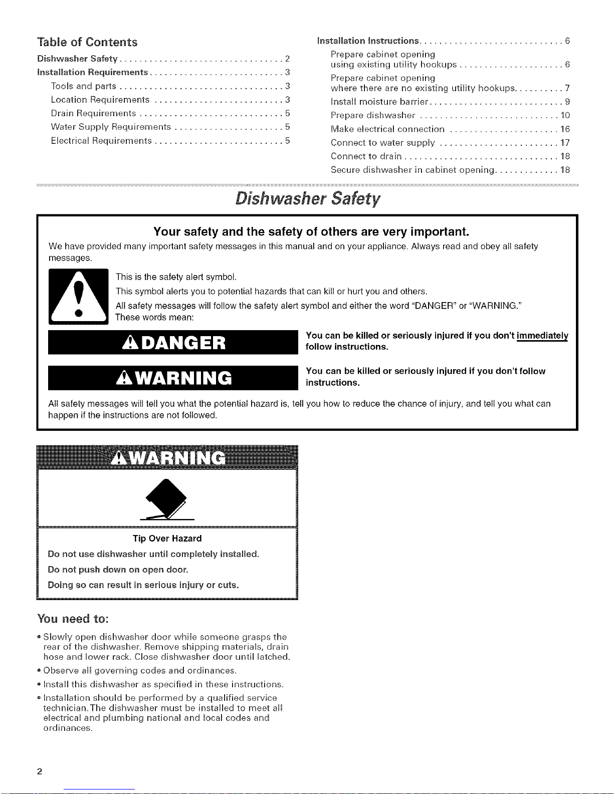
Tip Over Hazard
Do not use dishwasher until completely installed,
Do not push down on open door.
Doing so can result in serious injury or cuts.
You need to:
, Slowly open dishwasher door while someone grasps the
rear of the dishwasher. Remove shipping materials, drain
hose and lower rack Close dishwasher door until latched.
®Observe all governing codes and ordinances.
®Install this dishwasher as specified in these instructions,
Installation should be performed by a qualified service
technician.The dishwasher must be installed to meet all
electrical and plumbing national and local codes and
ordinances.
InstMlation Requirements
Location Requirements
TooJs and Parts
Gather the required tools and parts before starting
installation,
AH installations
Tools needed:
+ pliers
+ Phillips screwdriver
+ 5/16" and 1/4" nut drivers
or hex sockets
+ measuring tape or ruler
+ 10" adjustable wrench that
opens to 1-1/8" (2,9 cm)
+ flat+blade screwdriver
+ utility knife
+ 2 twist+on wire connectors
which are the proper size to
connect your household
wiring to 16+gauge wiring
in dishwasher
+ small level
+TORX_T15 screwdriver (if
installing custom front
panels)
mnaddition, for new installations
Tools needed:
+ electric drill with 1/2", 3/4"
and 1-1/2" hole saw bits
®small tubing cutter
+ wire stripper
+ 1-1/2"-2" screw-type clamp
if connecting to waste+tee
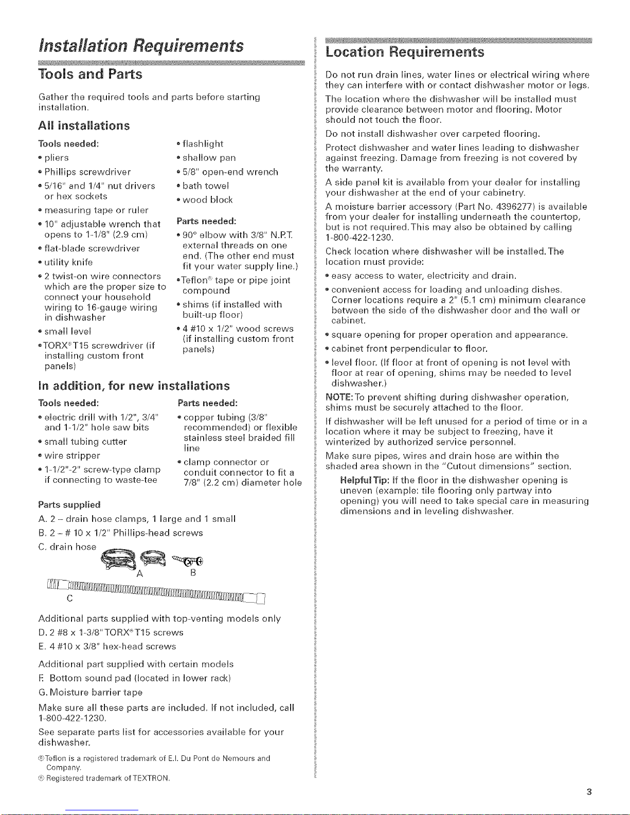
Parts supplied
A, 2 - drain hose clamps, 1 large and 1 small
B, 2 - # 10 x 1/2" Phillips-head screws
C, drain hose
+flashlight
+ shallow pan
+ 5/8" open-end wrench
®bath towel
+ wood block
Parts needed:
+90° elbow with 3/8" N,RT,
external threads on one
en& (The other end must
fit your water supply line,)
+Teflon :"tape or pipe joint
compound
+shims (if installed with
built+up floor)
+4 #10 x 1/2" wood screws
(if installing custom front
panels)
Parts needed:
+ copper tubing (3/8"
recommended) or flexible
stainless steel braided fill
line
+ clamp connector or
conduit connector to fit a
7/8" (2,2 cm) diameter hole
Do not run drain lines, water lines or electrical wiring where
they can interfere with or contact dishwasher motor or legs.
The location where the dishwasher will be installed must
provide clearance between motor and flooring. Motor
should not touch the floor.
Do not install dishwasher over carpeted flooring.
Protect dishwasher and water lines leading to dishwasher
against freezing. Damage from freezing is not covered by
the warranty.
A side panel kit is available from your dealer for installing
your dishwasher at the end of your cabinetr%
A moisture barrier accessory (Part No. 4396277} is available
from your dealer for installing underneath the countertop,
but is not required.This may also be obtained by calling
1-800-422-1230.
Check location where dishwasher wiii be installed. The
location must provide:
+ easy access to water, electricity and drain.
+ convenient access for loading and unloading dishes.
Corner locations require a 2" (5.1 cm) minimum clearance
between the side of the dishwasher door and the wail or
cabinet.
+ square opening for proper operation and appearance.
+ cabinet front perpendicular to floor.
+ level floor. (If floor at front of opening is not level with
floor at rear of opening, shims may be needed to level
dishwasher.)
NOTE:To prevent shifting during dishwasher operation,
shims must be securely attached to the floor.
If dishwasher will be left unused for a period of time or in a
location where it may be subject to freezing, have it
winterized by authorized service personnel.
Make sure pipes, wires and drain hose are within the
shaded area shown in the '+Cutout dimensions" section.
HelpfuJTip: If the floor in the dishwasher opening is
uneven (example: tile flooring only partway into
opening) you will need to take special care in measuring
dimensions and in leveling dishwasher.
B
Additional parts supplied with top-venting models only
D. 2 #8 x 1-3/8"TORX_T15 screws
E. 4 #10 x 3/8" hex+head screws
Additional part supplied with certain models
E Bottom sound pad (located in lower rack)
G. Moisture barrier tape
Make sure all these parts are included. If not included, call
1-800+422+1230.
See separate parts list for accessories available for your
dishwasher.
@Teflon is a registered trademark of E.!. Du Pont de Nemours and
Company
@Registered trademark of TEXTRON
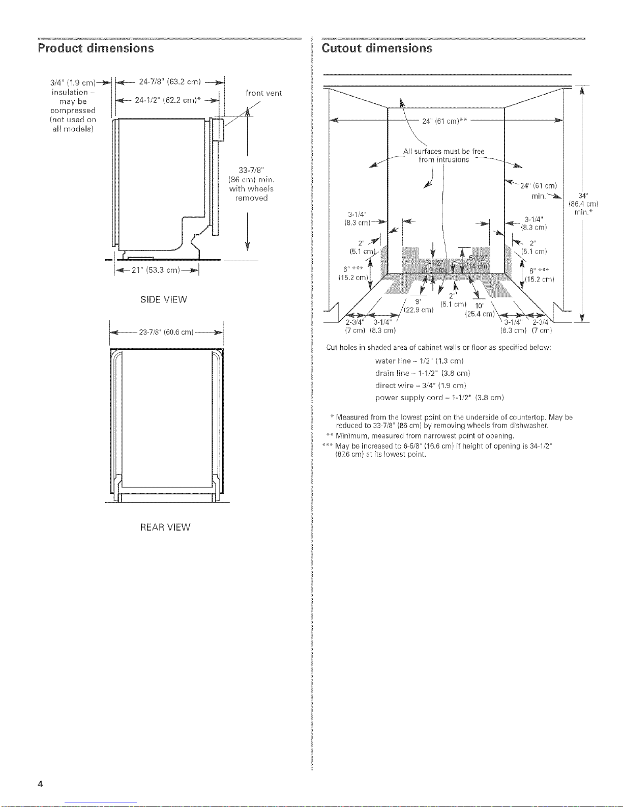
Product dimensions
3/4" (!.9 cm)_
insu lation -
may be
compressed
(not used on
al! models)
_F- 21" (53.3 cm)_
Cutout dimensions
----------------__ _
All surfaces must be free
_-- from intrusions
cm) _
3-1/4"
(8.3cm)
2"
(5.1cm)
r(15.2 cm)
SIDE VIEW
23-7/6" (60.6 cm)
REAR VIEW
(5.1 cm) 10" \
2-3/4" 3-I/4"
(7 cm) (6,3 cm) (6,3 cm) (7 cm)
Cut holes in shaded area of cabinet walls el' floor as specified below:
water line - 1/2" (1,3 cm)
drain line - 1-I/2" (3.8 cm)
direct wire - 3/4" (!,9 cm)
power supply cord - 1-1/2" (3.8 cm)
Measured from the lowest point on the underside of countertop. May be
reduced to 33-7/8" (86 cm) by removing wheels from dishwasher.
_ Minimum, measured from narrowest point of opening,
May be increased to 6-5/8" (16.6 cm) [f height of opening is 34-I/2"
(8}:6 cm) at its lowest point.
(25.4 cm)'
Drain Requirements
Electrical F equirements
Use the new drain hose suppibd with your dishwasher.
[ftMs is not iong enough, use a new drain hose with a
maximum length of 12 feet (3.7 m) that meets ai[ current
AHAM/IAPMO test standards, is resistant to heat and
detergent, and fits the 1" (2.5 cm) drain connector of the
dishwasher.
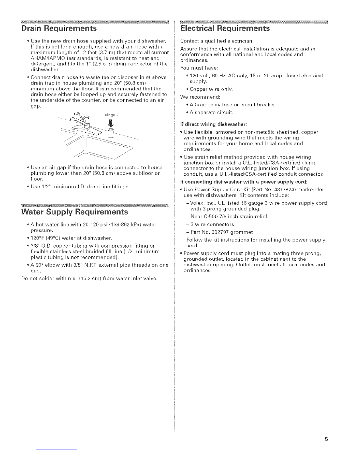
o Connect drain hose to waste tee or disposer inlet above
drain trap in house piumbing and 20" (50.8 cm)
minimum above the floor, it is recommended that the
drain hose either be hoped up and secureiy fastened to
the underside of the counter, or be connected to an air
gap.
air gap
o Use an air gap if the drain hose is connected to house
plumbing lower than 20" (50.8 cm) above subfloor or
floor.
Use 1/2" minimum LD. drain line fittings.
Water Supply Requirements
_A hot water line with 20-120 psi (138o862 kPa) water
pressure.
o 120°F (49°C) water at dishwasher.
o 3/8" O.D. copper tubing with compression fitting or
flexible stainless steel braided fill line (1/2" minimum
plastic tubing is not recommended}.
o A 90 ° elbow with 3/8" N.RT. external pipe threads on one
end.
Do not soJder within 6" (1B.2 cm} from water inJet vaJve.
Contact a qualified electrician.
Assure that the electrical installation is adequate and in
conformance with aii national and local codes and
ordinances.
You must have:
120_volt, 60 Hz, AC_only, 15 or 20 amp., fused electrical
suppl%
o Copper wire only.
We recommend:
o A timeodelay fuse or circuit breaker.
A separate circuit.
If direct wiring dishwasher:
o Use flexible, armored or non-metallic sheathed, copper
wire with grounding wire that meets the wiring
requirements for your home and local codes and
ordinances.
Use strain relief method provided with house wiring
junction box or install a U.LMisted/CSA-certified clamp
connector to the house wiring junction box. If using
conduit, use a U.h-listed/CSAocertified conduit connector.
If connecting dishwasher with a power supply cord:
Use Power Supply Cord Kit (Part No. 4317824) marked for
use with dishwashers. Kit contents include:
-Volex, [nc., UL listed 16 gauge 3 wire power supply cord
with 3 prong grounded plug.
- Neer C°500 7/8 inch strain relieL
- 3 wire connectors.
- Part No. 302797 grommet
Follow the kit instructions for installing the power supply
cord.
o Power supply cord must plug into a mating three prong,
grounded outlet, located in the cabinet next to the
dishwasher opening. Outlet must meet aii local codes and
ordinances.
/nstM/ation Instructions
EBectrical Shock Hazard
Disconnect electrical power at the fuse box or circuit
breaker box before installing dishwasher.
Failure to do so can result in death or electrical shock.
1. Disconnect power.
2. Turn off water supply.
mnstall the drain hose
_MPORTANT: Always use a new drain hose even when
installing a new replacement dishwasher,
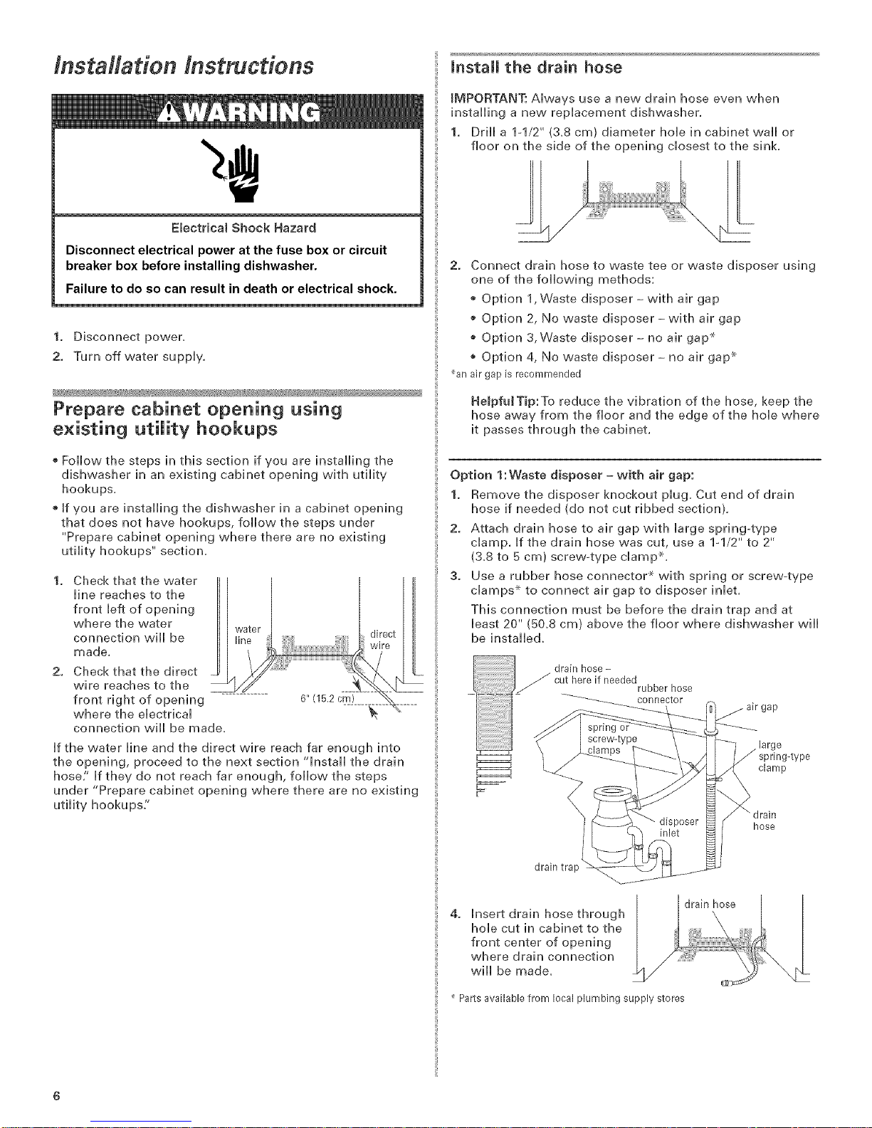
1. Drill a 1-1/2" (&8 cm) diameter hole in cabinet wail or
floor on the side of the opening closest to the sink,
L
2. Connect drain hose to waste tee or waste disposer using
one of the following methods:
o Option 1,Waste disposer- with air gap
o Option 2, No waste disposer- with air gap
o Option 3, Waste disposer- no air gap _
Option 4, No waste disposer - no air gap _
%n air gap is recommended
Prepare cabinet opening using
existing utility hookups
Follow the steps in this section if you are installing the
dishwasher in an existing cabinet opening with utility
hookups,
®If you are installing the dishwasher in a cabinet opening
that does not have hookups, follow the steps under
"Prepare cabinet opening where there are no existing
utility hookups" section,
Check that the water
line reaches to the
front left of opening
where the water
connection will be
made,
Check that the direct
wire reaches to the
front right of opening
where the electrical
connection will be made,
if the water line and the direct wire reach far enough into
the opening, proceed to the next section "install the drain
hose/' If they do not reach far enough, follow the steps
under "Prepare cabinet opening where there are no existing
utility hookups:'
6" (15.2 cm) _/
direct
HelpfuJTip:To reduce the vibration of the hose, keep the
hose away from the floor and the edge of the hole where
it passes through the cabinet.
Option 1:Waste disposer = with air gap:
1. Remove the disposer knockout plug. Cut end of drain
hose if needed (do not cut ribbed section).
2. Attach drain hose to air gap with large spring4ype
clamp, if the drain hose was cut, use a lq/2" to 2"
(3.8 to 5 cm) screw4ype clamp _,
3. Use a rubber hose connector _ with spring or screw-type
clamps ×-to connect air gap to disposer inlet.
This connection must be before the drain trap and at
least 20" (50.8 cm) above the floor where dishwasher will
be installed.
drain hose -
cut hereif needed
rubberhose
connector
large
spring-type
clamp
"" drain
hose
drain trap
4. Insert drain hose through
hole cut in cabinet to the
front center of opening
where drain connection
will be made,
Parts available from local plumbing supply stores
drain hose
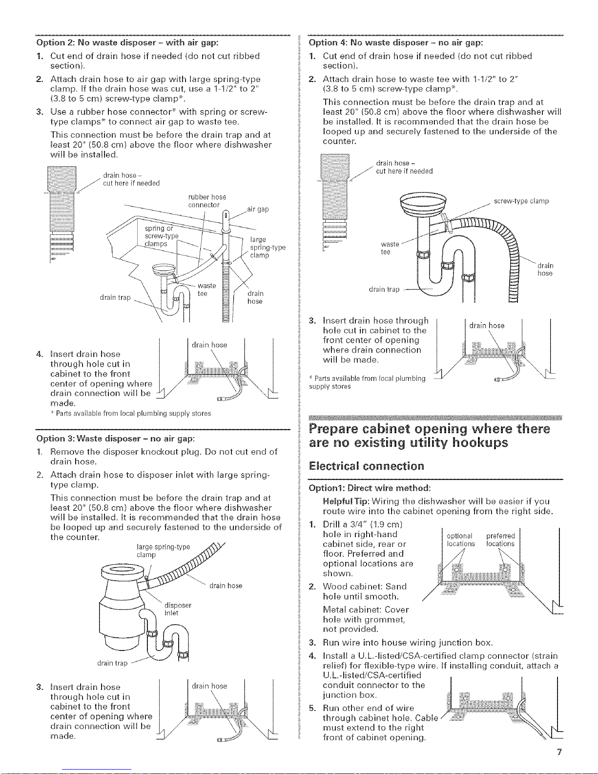
Option 2: No waste disposer = with air gap:
1. Cut end of drain hose if needed {do not cut ribbed
section),
2. Attach drain hose to air gap with large spring-type
clamp. If the drain hose was cut, use a 1-1/2" to 2"
(3.8 to 5 cm) screw-type clamp x-,
3. Use a rubber hose connector _ with spring or screw-
type damps .×to connect air gap to waste tee.
This connection must be before the drain trap and at
least 20" (50.8 cm) above the floor where dishwasher
will be installe&
drain hose-
Option 4: No waste disposer = no air gap:
1. Cut end of drain hose if needed (do not cut ribbed
section),
2. Attach drain hose to waste tee with 1-1/2" to 2"
(&8 to 5 cm) screw4ype clamp ×,
This connection must be before the drain trap and at
least 20" (50,8 cm) above the floor w,here dishwasher will
be installed. It is recommended that the drain hose be
looped up and securely fastened to the underside of the
counter.
drain hose -
_/ cut here if needed
disposer
inlet
/
rubber hose
connector
large
spring-type
drain
drain hose
drain hose
drain hose
_ cut here if needed
_g or
drain trap hose
|
insert drain hose |
through hob cut in
cabinet to the front
center of opening where
drain connection wiil be
made.
Parts available from local plumbing supply stores
Option 3: Waste disposer - no air gap:
1. Remove the disposer knockout plug. Do not cut end of
drain hose.
Attach drain hose to disposer inlet with large spring-
type clamp.
This connection must be before the drain trap and at
least 20" (50.8 cm) above the floor where dishwasher
will be installed, it is recommended that the drain hose
be looped up and securely fastened to the underside of
the counter.
large spring-type
clamp
drain trap
insert drain hose |
through hob cut in
cabinet to the front
center of opening where
drain connection will be j
made.
!
screw4ype clamp
J
hose
teeWaSteJ
drain trap
3. Insert drain hose through /
hole cut in cabinet to the
front center of opening
where drain connection
will be made_
Parts available from local plumbing
supply stores
drain hose
Prepare cabinet opening where there
are no existing utility hookups
Electrical connection
Option1: Direct wire method:
HelpfuJTip: Wiring the dishwasher will be easier if you
route wire into the cabinet opening from the right side.
1. Drill a 3/4" (1,9 cm)
hole in right-hand optional preferred
cabinet side, rear or locations locations
floor. Preferred and
optional locations are
shown.
2. Wood cabinet: Sand
hole until smootL
Metal cabinet: Cover
hole with grommet,
not provided.
3. Run wire into house wiring junction box.
4. Install a U.L.-listed/CSA-certified clamp connector (strain
relief) for flexible-type wire. If installing conduit, attach a
U.L.-listed/CSA-certified
conduit connector to the
junction box.
5. Run other end of wire
through cabinet hole.
must extend to the right
front of cabinet opening.
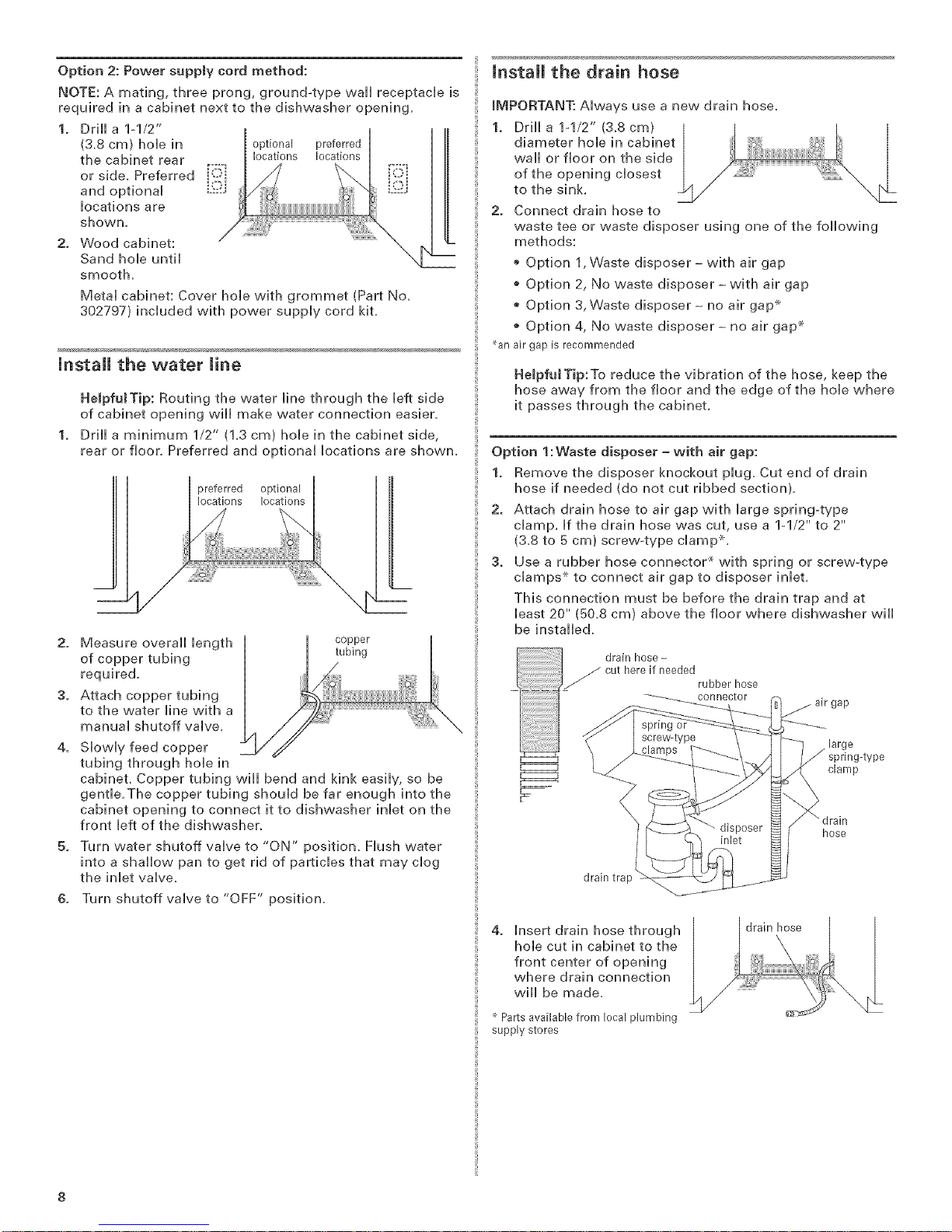
Option2:Powersupplycordmethod:
NOTE:A mating,threeprong,ground-typewallreceptacHeis
requiredinacabinetnexttothedishwasheropening.
1. Drilla1ol/2" I I
(3.8cm)holein optionalpreferred
thecabinetrear ,,--__ns Ioc_ _)_.,.,,
and optional _]
locations are
orside, Preferred !_ <
2. Woodcabinet:
SandhoHeuntil
smooth.
MetaH cabinet: Cover hoHe with grommet (Part No.
302797) [ncHuded with power suppHy cord kit.
install the water line
HelpfutTip: Routing the water Hne through the Heft side
of cabinet opening wHH make water connection easier.
DrHH a minimum 1/2" (1.3 cm) hoHe in the cabinet side,
rear or floor. Preferred and optionaH Hocations are shown.
preferred optional
locations locations
2. Measure overaHH Hength
of copper tubing
required.
3. Attach copper tubing
to the water Hine with a
manuaH shutoff valve.
Slowly feed copper
tubing through hole in
cabinet. Copper tubing will bend and kink easily, so be
gentle.The copper tubing should be far enough into the
cabinet opening to connect it to dishwasher inlet on the
front left of the dishwasher.
Turn water shutoff vaHve to "ON" position. Hush water
into a shallow pan to get rid of particles that may dog
the inHet valve.
6. Turn shutoff vaHve to "OFF" position.
copper
tubing
mnstaH the drain hose
IMPORTANT: AHways use a new drain hose.
1. DrIHHa 1-1/2" (3.8 cm)
diameter hoHe in cabinet
waHH or floor on the side
of the opening cHosest
to the sink.
2. Connect drain hose to
waste tee or waste disposer using one of the foHHowing
methods:
o Option 1,Waste disposer- with air gap
o Option 2, No waste disposer- with air gap
o Option 3, Waste disposer- no air gap _
Option 4, No waste disposer- no air gap _
_an air gap is recommended
HelpfuJTip:To reduce the vibration of the hose, keep the
hose away from the floor and the edge of the hoHe where
it passes through the cabinet.
Option 1:Waste disposer- with air gap:
1. Remove the disposer knockout pHug. Cut end of drain
hose if needed (do not cut ribbed section).
2. Attach drain hose to air gap with Harge spring-type
champ. Hfthe drain hose was cut, use a 1_1/2" to 2"
(3.8 to 5 cm) screw-type cHamp x-.
3. Use a rubber hose connector _ with spring or screw-type
cHamps x-to connect air gap to disposer inHet.
This connection must be before the drain trap and at
Heast 20" (50.8 cm) above the floor where dishwasher wiHH
be installed.
drain hose -
cut here if needed
rubber hose
connector
large
spring-type
clamp
"" drain
hose
drain trap
4. Insert drain hose through
hoHe cut in cabinet to the
front center of opening
where drain connection
w[HH be made.
Parts available from local plumbing
supply stores

Option 2: No waste disposer = with air gap:
1. Cut and of drain hose if needed {do not cut ribbed
sectionl,
2. Attach drain hose to air gap with large spring-type
clamp. If the drain hose was cut, use a lq/2" to 2"
(3.8 to 5 cm) screw-type clamp x,
3. Use a rubber hose connector* with spring or screw_type
clamps _ to connect air gap to waste tee.
This connection must be before the drain trap and at
least 20" (50.8 cm) above the floor where dishwasher will
be installed.
drain hose-
cut here if needed
/
rubber hose
connector
large
spring-type
drain trap hose
insert drain hose |
through hole cut in
drain hose
drain
cabinet to the front
center of opening where
drain connection will be
made, /
Option 4: No waste disposer = no air gap:
1. Cut end of drain hose if needed (do not cut ribbed
section),
2. Attach drain hose to waste tee with 1-1/2" to 2"
(3.8 to 5 cm) screvv_type clamp _,
This connection must be before the drain trap and at
bast 20" (50.8 cm) above the floor where dishwasher will
be installed, it is recommended that the drain hose be
looped up and securely fastened to the underside of the
counter,
drain hose -
cut here if needed
screw-type clamp
tee
waste/
drain trap
3. insert drain hose through | drain hose
hole cut in cabinet to the
front center of opening
where drain connection
will be made ....................
Parts available from local plumbing
supply stores
hose
Parts available from local plumbing supply stores
Option 3: Waste disposer = no air gap:
1, Remove the disposer knockout plug, Do not cut end of
drain hose,
Attach drain hose to disposer inlet with large spring-type
clamp.
This connection must be before the drain trap and at
least 20" (50.8 am} above the floor where dishwasher will
be installed, it is recommended that the drain hose be
looped up and securely fastened to the underside of the
counter.
large spring-type
clamp
drain hose
disposer
inlet
drain trap
insert drain hose
through hob cut in
cabinet to the front
center of opening where
drain connection will be
_/_ drain hose
made.
install moisture battier (onsome models)
1. Make sure the area under the cabinet is clean and dry
for installation of the moisture barrier.
2. Remove the backing of the moisture barrier and apply to
underside of the countertop along the front edge of the
counter.
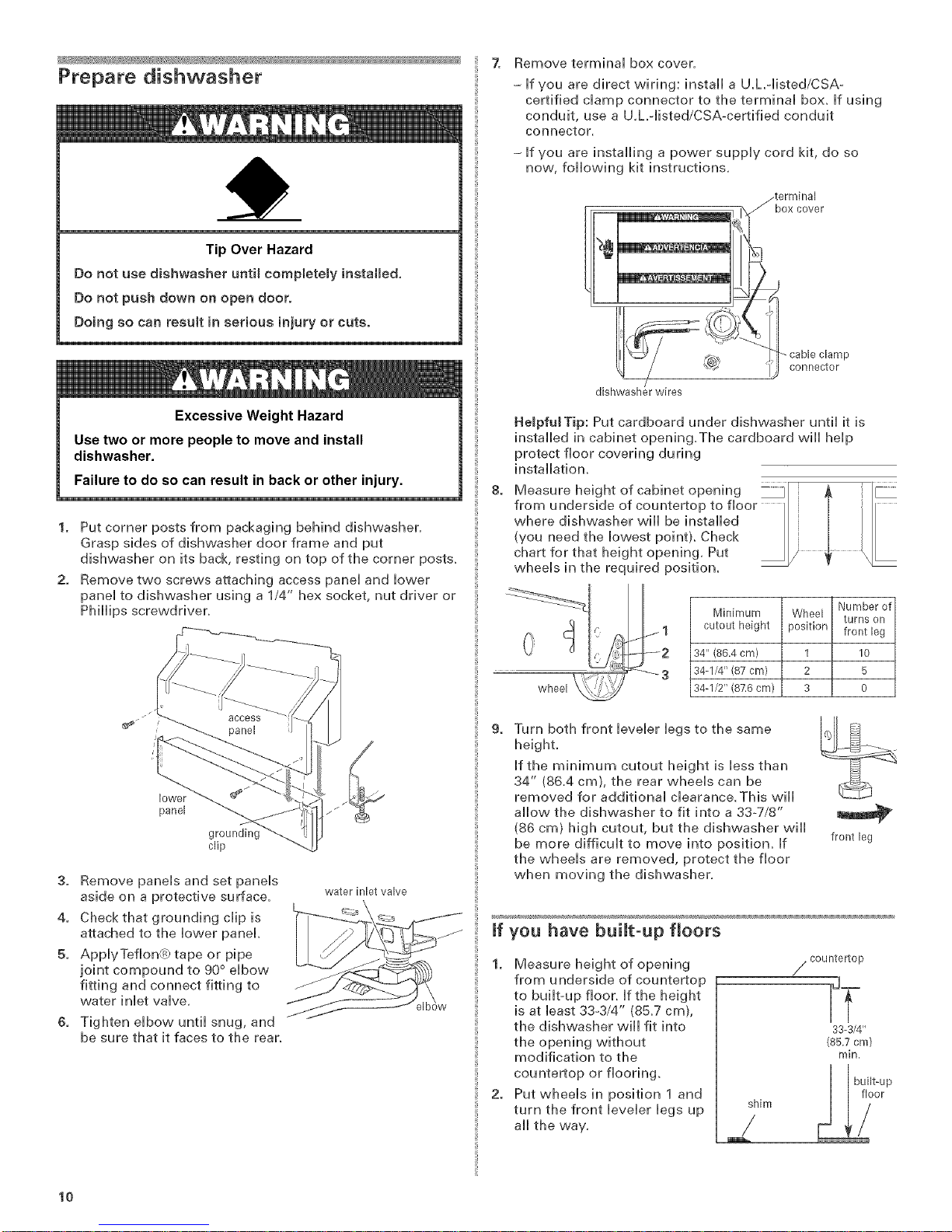
Prepare dishwasher
Tip Over Hazard
Do net use dishwasher until completely installed,
Do not push down on open door.
Do}ng so can result }n serious injury or cuts.
Z Remove terminal box cover.
= if you are direct wiring: install a U.h°listed/CSA-
certified clamp connector to the terminal box. if using
conduit, use a U.h°listed/CSA-certified conduit
connector.
= if you are installing a power supply cord kit, do so
now, following kit instructions,
_terminal
box cover
/,i
_ cable clamp
Excessive Weight Hazard
Use two or more people to move and install
dishwasher.
Failure to do so can result in back or other injury.
1. Put corner posts from packaging behind dishwasher.
Grasp sides of dishwasher door frame and put
dishwasher on its back, resting on top of the corner posts.
2. Remove two screws attaching access panel and bwer
panel to dishwasher using a 1/4" hex socket, nut driver or
PhHHps screwdriver.
lower
panel
clip
3. Remove panels and set panels
aside on a protective surface, water inlet valve
4. Check that grounding clip is
attached to the lower panel.
5. ApplyTeflon@ tape or pipe
joint compound to 90 ° elbow
fitting and connect fitting to
water inlet valve.
i
Tighten elbow until snug, and
be sure that it faces to the rear,
dishwasher wires
Helpful Tip: Put cardboard under dishwasher until it is
installed in cabinet opening.The cardboard will help
protect floor covering during
installation.
8=
Measure height of cabinet opening _l & "
from underside of countertop to floor II | ] /I
where dishwasher will be installed |
(you need the lowest point}. Check II / |/I
chart for that height opening, Put _ / _ X
wheels in the required position. _ -
9=
Turn both front leveler legs to the same
height,
If the minimum cutout height is less than
34" (86.4 cm), the rear wheels can be
removed for additional clearance. This will
allow the dishwasher to fit into a 33o7/8"
(86 cm) high cutout, but the dishwasher will
be more difficult to move into position. If
the wheels are removed, protect the floor
when moving the dishwasher.
/
Minimum
cutout height
34" (86.4 cm)
34-1/4" (87 cm)
34-I/2" (87.6 cm)
'iJ connector
1 I0
2 5
3 0
if you have built-up floors
1. Measure height of opening
from underside of countertop
to built-up floor. If the height
is at least 33-3/4" (85.7 cm),
the dishwasher will fit into
the opening without
modification to the
countertop or flooring.
2. Put wheels in position 1 and
turn the front leveler legs up
aii the way.
f countertop
shirr, _ _O_p
front leg
Ir
33-3/4"
(8&7 cm)
rain.
lO
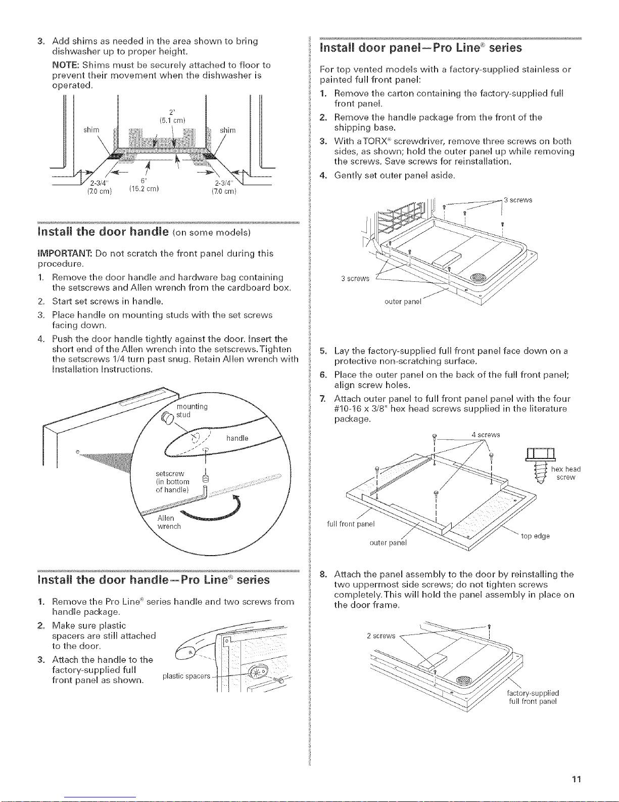
Addshimsasneededintheareashowntobring
dishwasheruptoproperheight.
NOTE:ShimsmustbesecureHyattachedtofloorto
preventtheirmovementwhenthedishwasheris
operated,
2"
shim
2-3/4" 6" 2-3/4"
(70 cm) (15.2cm) (70 cm)
mnstall the door handle (onsomemodeHs)
IMPORTANT: Do not scratch the front paneH during this
procedure,
1, Remove the door handHe and hardware bag containing
the setscrews and AHen wrench from the cardboard box,
2. Start set screws in handle.
3,
Place handle on mounting studs with the set screws
facing down.
4.
Push the door handHe tightly against the door. Insert the
short end of the AHHenwrench into the setscrews. Tighten
the setscrews 1/4 turn past snug. Retain Allen wrench with
Installation Instructions.
(5.1cm)
stud
g
_) / handle
Install door panel--Pro Line _ series
For top vented models with a factory-supplied stainless or
painted full front panel:
1. Remove the carton containing the factory-supplied full
front panel.
2. Remove the handle package from the front of the
shipping base.
3. With aTQRX screwdriver, remove three screws on both
sides, as shown; hold the outer panel up while removing
the screws. Save screws for reinstallation.
4. Gently set outer panel aside.
3 screws
outer [
5. Lay the factory-supplied full front panel face down on a
protective non-scratching surface.
6. Place the outer panel on the back of the full front panel;
align screw holes.
7. Attach outer panel to full front panel panel with the four
#10q6 x 3/8" hex head screws supplied in the literature
package.
4 screws
setscrew
(in bottom
of handle)
....)
wrench
Install the door handle--Pro Line _"_series
1. Remove the Pro Line _:'series handle and two screws from
handle package.
2. Make sure plastic
spacers are still attached
to the door.
Attach the handle to the
factory-supplied full
front panel as shovvn,
plastic spacers
full front panel
outer panel
8. Attach the panel assembly to the door by reinstalling the
two uppermost side screws; do not tighten screws
completely.This will hold the panel assembly in place on
the door frame.
2 screws
,p edge
factory-supplied
full front panel
11
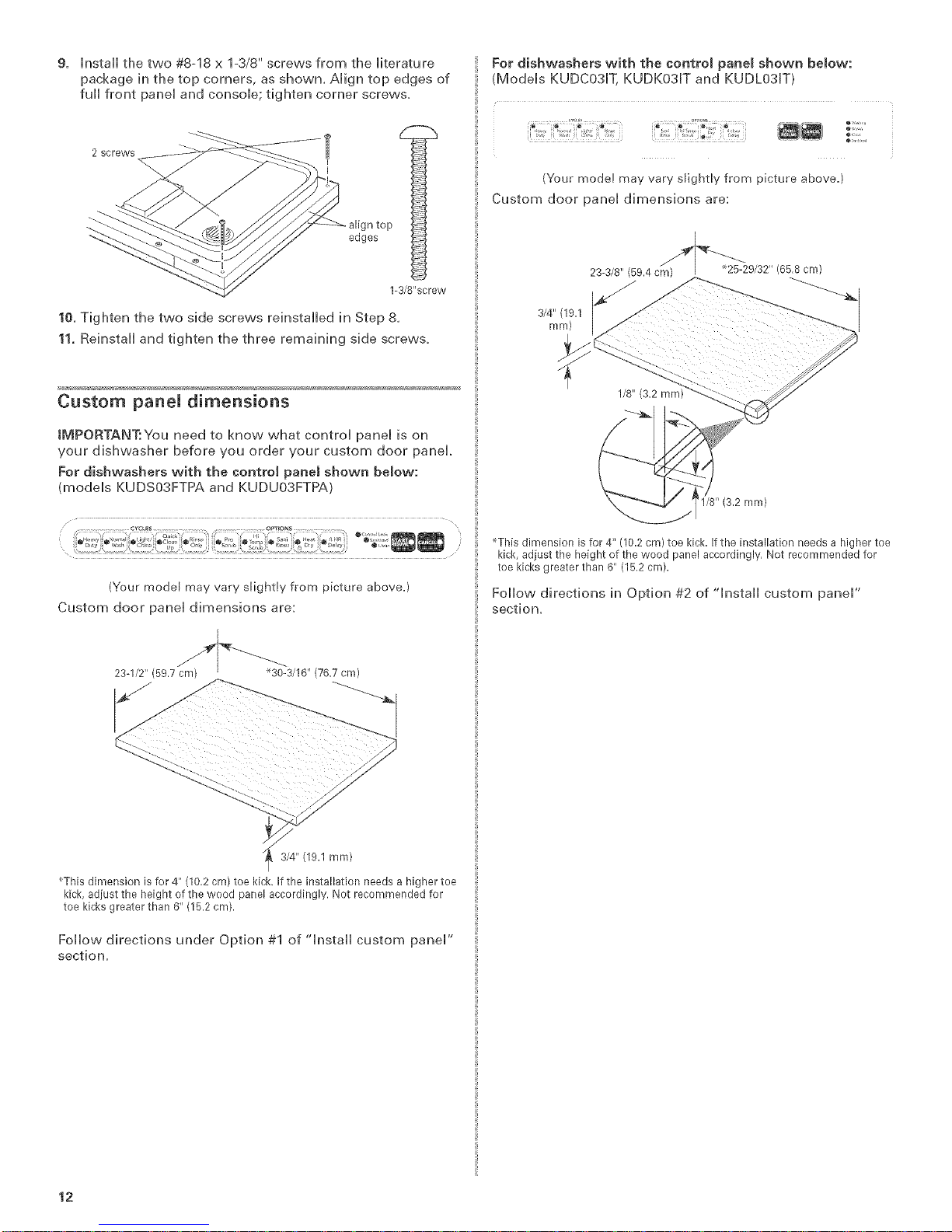
9. HnstaHHthe two #8-18 x 1-3/8" screws from the Hiterature
package in the top corners, as shown, AHign top edges of
fuHHfront paneH and consoHe; tighten corner screws,
2 screws
I
top
edges
0l
1-3/8"screw
10. Tighten the two side screws reinstaHHedin Step 8,
11. ReinstaHHand tighten the three remaining side screws,
Custom paneU dimensions
IMPORTANT:You need to know what controH paneH is on
your dishwasher before you order your custom door panel
For dishwashers with the controJ panel shown below:
(modeHs KUDSO3FTPA and KUDUO3FTPA)
For dishwashers with the control panel shown beJow:
(ModeHs KUDCO31T, KUDKO31T and KUDLO31T)
(Your model may vary slightly from picture above.)
Custom door paneH dimensions are:
3/4" (19.1
ram)
1/8" (3.2 mm)
(Your modeF may vary sFightly from picture above.)
Custom door panei dimensions are:
23-I/2" (597 cm) _30 3/10 (767 cm)
3/4" (19.1 ram)
_This dimension is for 4" (10.2 cm) toe kick. If the installation needs a higher toe
kick, adiust the height of the wood panel accordingly. Not recommended for
toe kicks greater than 6" (15.2 cm).
Foiiow directions under Option #1 of "instaii custom panei"
section,
_This dimension is for 4" (10.2 cm) toe kick. If the installation needs a higher toe
kick, adjust the height of the wood panel accordingly. Not recommended for
toe kicks greater than 6" (15.2 cm).
FoHHow directions in Option #2 of 'qnstaHH custom paneH"
section.
12
 Loading...